Hello,
I need a circuit to output 0-10v from a 5v PWM coming from an Atmel controller. First, I tried;
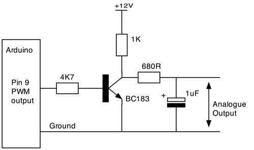
That works but as the PWM duty cycle goes up the Analog out goes down and vice versa. But I need them to be the same because I am running a PWM device (fan) to go along with the analog 0-10v out (LED Controller).
I also tried inverting with;
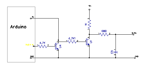
But the Analog out is not linear and the controller voltage regulator gets pretty darn hot.

I also tried a non-inverting op amp but I only have 5v, 12v and ground. Without a -12v the Op Amp won't go to 0v.


I don't know what else to try. Any ideas?
Thanks in advance,
Robert


