Hi Guys

I’m making a breadboard to try using a graphic LCD display for the first time.
The LCD I’ve chosen is this one:
https://www.sparkfun.com/products/710... and here is it’s pinout from the data sheet:
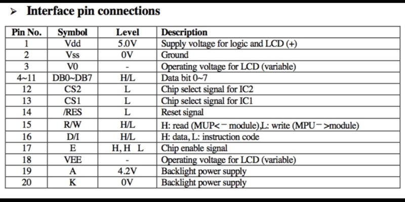
I’m familiar with all other pins from using character LCDs, but hoping someone can better explain the purpose of pins 3 & 18.
Usually, pin 3 is for a variable voltage to adjust LCD contrast with a pot used as a voltage divider, but then what is pin 18 for?
The product page on the Sparkfun site has a Pong Clock project, and I see this in the schematic:
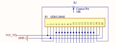
Is that a mistake? Because that’s just a fixed 10k resistor with the wiper connected to nothing.
Cheers, Art.


