Author Topic: 5 Transistor ESR Meter Design  (Read 308337 times)

0 Members and 1 Guest are viewing this topic.

Offline Jay_Diddy_BTopic starter

  • Super Contributor
  • ***
  • Posts: 2733
  • Country: ca
5 Transistor ESR Meter Design
« on: December 14, 2012, 04:07:37 am »
Hi Forum Members,

There seem to be as many ESR meter designs as people who use them. I have decided to share my ESR meter design with the group.
Strictly speaking this ESR meter does not measure ESR, it measures the impedance of the capacitor under test at 100kHz. For Capacitors larger than a few uF this is approximately equal to the ESR.

ESR meter do not need to be precise, it most instances a bad capacitor will have any ESR many times that of a good one.

When I was kid, radio manufacturers would sell transistor radios based on the number of transistor in them. This is a 5 transistor ESR meter. The only IC that used is a 5V regulator. The circuit should also work directly from 3 or 4 AA batteries without the regulator. The design should work with any general purpose transistors. The diodes in the meter circuit will effect the meter scale. Use small signal Schottky diodes such as 1N5711, common diodes like BAT54 have too much capacitance. OA91 or similar Ge diode should also work.

10th Anniversary Edition

I shared a modified version the ESR meter in this message:

https://www.eevblog.com/forum/projects/5-transistor-esr-meter-design/msg4608886/#msg4608886

Two additional transistors are used to detect if the resistance of the capacitor being tested is less than 25 \$\Omega\$  All the other features remain the same. The new design was generated in KICAD version 5.00


The maximum voltage on the capacitor under test is 100mV. This allows for in-circuit testing.

The design started with modelling the circuit in LTspice:


The building blocks are labelled.

This is the result of the LTspice modelling, it shows how the meter deflection changes with ESR.


This good because it gives an expanded scale.

From the LTspice model, I made the OrCad schematic:


And then the board layout, I used SMD parts, but thru hole parts could also be used.


The circuit was made from the above design and the components attached:


The meter circuit was hooked up. The meter deflection was measure using some low value resistor. Artwork for a new meter scale was drawn using Corel Draw. The meter scale was printed on Photo paper to be attached to the meter.


The final assembly was completed. Here is a view of the inside of the ESR  meter:


And the Outside:


If you build this, remember to discharge capacitors before using.
Current consumption is 26mA, that is about 25 hours of use.

Regards,

Jay_Diddy_B aka John
« Last Edit: December 30, 2022, 10:50:50 pm by Jay_Diddy_B »
 

Offline BravoV

  • Super Contributor
  • ***
  • Posts: 7547
  • Country: 00
  • +++ ATH1
Re: 5 Transistor ESR Meter Design
« Reply #1 on: December 14, 2012, 04:15:57 am »
Thanks for sharing !  :-+

Any chance you could share the LTSpice file by attaching it to your 1st post ? Zip it 1st then attach.

Calling Kripton2035 ...   :)
« Last Edit: December 14, 2012, 04:18:41 am by BravoV »
 
The following users thanked this post: m3vuv, bmdaly, Synthtech

Offline Jay_Diddy_BTopic starter

  • Super Contributor
  • ***
  • Posts: 2733
  • Country: ca
Re: 5 Transistor ESR Meter Design
« Reply #2 on: December 14, 2012, 04:39:14 am »
I have added the LTspice file to the original message.

To obtain the graph.

Run the LTspice file. The circuit will run 15 times.
This from this SPICE Directive:

.step param R LIST 0.0001 0.1 0.2 0.5 1 2 4 6 8 10 12 14 16 18 20

When the analysis is finished from the VIEW menu 'Spice Error Log'

Then right click in the Error log window.

Click plot .step'ed .meas data

The curve will then be displayed.


Jay_Diddy_B aka John

 
The following users thanked this post: m3vuv

Offline toli

  • Frequent Contributor
  • **
  • Posts: 313
  • Country: il
Re: 5 Transistor ESR Meter Design
« Reply #3 on: December 14, 2012, 07:42:57 am »
Very nice work  :-+

Would have built one myself, but came across this a couple of weeks ago. For that price I think I'll give that one a try. Some more info can be found here.
My DIY blog (mostly electronics/stereo related):
http://tolisdiy.com/
 

Offline Jay_Diddy_BTopic starter

  • Super Contributor
  • ***
  • Posts: 2733
  • Country: ca
Re: 5 Transistor ESR Meter Design
« Reply #4 on: December 14, 2012, 01:16:41 pm »
Toli,

I have had a look at the eBay offering. It looks a lot the AVR Transistor Tester that was started by Markus.

A very detailed description can be found here:

http://www.mikrocontroller.net/attachment/143988/TTester_096k.pdf

It is possible that the software has been expanded to add additional functions. If you search 'markus AVR transistor tester' and look at the images you will find a lot of variations of this design.

It doesn't look like the unit can make in-circuit measurements, but I might be wrong.

You will have to let us know how well this unit works. May be somebody else has one?

In my design, I wanted to see if I could do something useful with a few transistors.

Regards,

Jay_Diddy_B
 

Offline toli

  • Frequent Contributor
  • **
  • Posts: 313
  • Country: il
Re: 5 Transistor ESR Meter Design
« Reply #5 on: December 14, 2012, 01:56:45 pm »
1. It is similar but of a later version. You can read more in the link I added to diyAudio forum.
2. Says the maximum voltage in the capacitor/ESR measurement range is 300mV, so it should be good for in circuit measurements as well.
My DIY blog (mostly electronics/stereo related):
http://tolisdiy.com/
 

Offline cwalex

  • Frequent Contributor
  • **
  • Posts: 299
  • Country: au
Re: 5 Transistor ESR Meter Design
« Reply #6 on: December 15, 2012, 11:49:36 am »
That looks awesome! Really professional finish, looks like you used a cnc mill for a lot of it.  :-+
 

Offline Jay_Diddy_BTopic starter

  • Super Contributor
  • ***
  • Posts: 2733
  • Country: ca
Re: 5 Transistor ESR Meter Design
« Reply #7 on: December 15, 2012, 02:57:36 pm »
cwalex and the group,

The circuit board and the front panel were made with a LPKF Protomat C60.


Here are some of the capabilities of this awesome machine:

  • Minimum Track Width 4 mil (0.1 mm)
    Minimum Insulation Width 4 mil (0.1 mm)
    Minimum Drill Hole Size 8 mil (0.2 mm)
    Working Area 13.4" x 7.8" (340 mm x 240 mm)
    Resolution 0.3125 mil (7.937 µm)
    Repeatability +/- 0.2 mil (5 µm)
    Precision of Front-to-Back Alignment +/- 0.8 mil (20 µm)
    Spindle Motor 3 phase-motor, 5,000-60,000 rpm, software controlled
    Tool Change semi-automatic, software prompted
    Tool Collet 1/8" quick release collet
    Drilling Speed 90 strokes / minute
    Travel Speed 1.575" per second (40 mm/sec)
    Milling Depth Sensing coaxial mechanical sensing
    X/Y Positioning System stepper motors, precision lead screws
    ActiveCAM® anti-backlash Supermuts®
    X/Y Linear System precision linear bushings and shafts
    Z Drive electromagnetic with hydraulic damper
    Dimensions (w / h / d) 17" x 14" x 22.25" (430 x 355 x 565 mm)
    Weight 53 lb. (24 kg)
    Power Consumption 200 VA


I was extremely lucky to find this, complete with the tools, vacuum and software at a reasonable price.

After milling the board was tinned using MG Chemicals 'Liquid Tin'.

http://www.mgchemicals.com/products/prototyping-and-circuit-repair/prototyping/liquid-tin-421/


Jay_Diddy_B
« Last Edit: November 19, 2013, 08:44:57 pm by Jay_Diddy_B »
 

Offline FenderBender

  • Super Contributor
  • ***
  • Posts: 1115
  • Country: us
    • The Solid State Workshop
Re: 5 Transistor ESR Meter Design
« Reply #8 on: December 16, 2012, 06:35:08 pm »
Did you just use some precision resistors for setting the scale? How many did you use?
 

alm

  • Guest
Re: 5 Transistor ESR Meter Design
« Reply #9 on: December 16, 2012, 07:17:29 pm »
Only five transistors... plus a voltage regulator with more than a dozen transistors ;)
 

Offline Jay_Diddy_BTopic starter

  • Super Contributor
  • ***
  • Posts: 2733
  • Country: ca
Re: 5 Transistor ESR Meter Design
« Reply #10 on: December 16, 2012, 07:18:59 pm »
FenderBender & the group,


I would suggest that you get 5 x 1 Ohm and 4 x 10 Ohm  1% resistors

This lets you get the following values:

0.2 Ohm 5 x 1 Ohm in parallel

0.25 Ohm 4 x 1 Ohm in parallel

0.333 Ohm 3 x 1 Ohm in parallel

0.5 Ohm 2 x 1 Ohm in parallel

1 Ohm 1 x 1 Ohm

1.5 Ohm 1 x 1 Ohm + 2 x 1 Ohm in parallel

2 Ohm 2 X 1 Ohm in series

2.5 Ohm 4 x 10 Ohm in parallel

3 Ohm 3 x 1 Ohm in series

4 Ohm 4 x 1 Ohm in series

5 Ohm 2 x 10 Ohm in parallel

Then add 1 Ohm in series to get 6, 7, 8, 9 Ohms

10 Ohms one 10 Ohm resistor


I measured the deflection with the original meter scale. Plotted a graph in Excel and calculated the deflection angles for the marks on the meter.

Keep the leads short especially when measuring the lower values.

Does this make sense ?

After I had finished the ESR meter I checked the calibration with some electrolytic capacitors that had been measured with a HP 4275A LCR (Z) Meter. This LCR meter works at frequencies from 10 kHz to 10 MHz, has a basic accuracy of 0.1% and 5 1/2 Digit display. :-+

Jay Diddy B
 

Offline FenderBender

  • Super Contributor
  • ***
  • Posts: 1115
  • Country: us
    • The Solid State Workshop
Re: 5 Transistor ESR Meter Design
« Reply #11 on: December 16, 2012, 07:43:31 pm »
So you used the 50uA scale since it is a linear scale. You measured the total angle of that scale? And then you did some proportions or something?

Corel Draw makes this easy? I understand how you did the math. Not so sure how I would go about drawing an accurate scale. I have Gimp..not too fluent in it.
 

Offline SeanB

  • Super Contributor
  • ***
  • Posts: 16276
  • Country: za
Re: 5 Transistor ESR Meter Design
« Reply #12 on: December 16, 2012, 07:55:23 pm »
I did a similar thing with mine, just skipped the printing of the scale thing. Used white out to remove the original scale markings, then sat with some resistors and did the same plotting of where the pointer was deflected to, then wrote the values with a Rotring drafting pen. Not the neatest or the most accurate, but does the job.
 

Offline Jay_Diddy_BTopic starter

  • Super Contributor
  • ***
  • Posts: 2733
  • Country: ca
Re: 5 Transistor ESR Meter Design
« Reply #13 on: December 16, 2012, 08:22:15 pm »
FenderBender & the group,

I measured the meter that I had using digital caliper. In my case the meter was 90o total deflection. Corel Draw defines 0o as vertical. So the angles required are +/- 45o.

Here is an image of the scale under construction:


The construction lines were deleted when the scale was finished.

Corel Draw is probably not the best software to us for this, but it is what I had available.

There is some special software available for doing custom scales. Here is a link to one that get good reviews:

http://tonnesoftware.com/meter2.html

I believe the MeterBasic, free version, only supports linear scales. I could not justify the $ for one meter.

Jay Diddy B
« Last Edit: January 25, 2013, 09:54:39 pm by Jay_Diddy_B »
 

Online EEVblog

  • Administrator
  • *****
  • Posts: 37728
  • Country: au
    • EEVblog
Re: 5 Transistor ESR Meter Design
« Reply #14 on: December 21, 2012, 03:42:24 am »
Old Skool, nice!  :-+

Dave.
 

Offline KD0CAC John

  • Frequent Contributor
  • **
  • Posts: 707
  • Country: us
Re: 5 Transistor ESR Meter Design
« Reply #15 on: December 21, 2012, 02:42:18 pm »
Both the ARRL [ American Radio Relay league ] books , handbook & antenna book ,  have CDs in then with lots of software , ment for ham radio electronic repair & building .
I would say free , except you have to buy the books :) 
 

Offline HardBoot

  • Regular Contributor
  • *
  • Posts: 160
  • Country: ca
Re: 5 Transistor ESR Meter Design
« Reply #16 on: December 23, 2012, 06:12:03 am »
Really cool gadget, wish I could buy something like that for a few bucks and instead of a meter output to a micro, then a device could monitor it's own caps.
 

Offline Jay_Diddy_BTopic starter

  • Super Contributor
  • ***
  • Posts: 2733
  • Country: ca
Re: 5 Transistor ESR Meter Design
« Reply #17 on: January 10, 2013, 09:34:38 pm »
Hi group,

Has anybody else built this ESR?

Would there be any interest in a thru-hole circuit board design?

Regards,


Jay_Diddy_B


Offline redlandman

  • Newbie
  • Posts: 1
Re: 5 Transistor ESR Meter Design
« Reply #18 on: January 11, 2013, 04:59:05 am »
Jay_Diddy_B

I really like the design. I'd like to build it on a single sided board with standard componenets. I've made a few PCB's, but havn't been able to use any of the PCB design tools. I think it would be a great project, as yours has very good low end resolution.

Redlandman
 

Offline BravoV

  • Super Contributor
  • ***
  • Posts: 7547
  • Country: 00
  • +++ ATH1
Re: 5 Transistor ESR Meter Design
« Reply #19 on: November 10, 2013, 03:48:52 pm »
Bumping an old thread when looking at various diy esr meter circuits, Jay_Diddy_B, is there any possibilities of modifying the circuit, while still using jelly bean components, but the output is for digital volt meter instead of analog one ? Wishing this will not make the circuit overly complicated compared to the original version.  :-[

The reason I asked is finding a good analog meter is not easy, or at least cheap here in my place, which defies the original purpose that this circuit supposed to be simple, easy to build & cheap ESR meter.  :-//

Hope I'm not asking too much.

Offline kripton2035

  • Super Contributor
  • ***
  • Posts: 2581
  • Country: fr
    • kripton2035 schematics repository
Re: 5 Transistor ESR Meter Design
« Reply #20 on: November 10, 2013, 04:00:53 pm »
I ended up the same way when I build my esr meter years ago.
The go meter didnt exists, I focused on the analog poptronix esr meter
and did not find nor have in a desk the analog meter
so I used a bargraph and a lm3916 and it still works fine !
today I could use more segments (2x10 bargraphs) or the nice 28 segments display I found on ebay.

http://www.barmeter.com/en/viewproduct.asp?ID=184&XiajiID=0
 

Offline BravoV

  • Super Contributor
  • ***
  • Posts: 7547
  • Country: 00
  • +++ ATH1
Re: 5 Transistor ESR Meter Design
« Reply #21 on: November 10, 2013, 04:08:24 pm »
Yeah, maybe for experience EEs or pros which probably have many old unused T&M gadgets that still using analog meter that easily pull one for use, but its quite a hard for enthusiasts like me which usually do not have this kind of old analog gears around.  :'(

But my wish still reasonable I think, especially nowdays a DMM is a electronics noobs must have tool.
« Last Edit: November 10, 2013, 04:11:28 pm by BravoV »
 

Offline dannyf

  • Super Contributor
  • ***
  • Posts: 8221
  • Country: 00
Re: 5 Transistor ESR Meter Design
« Reply #22 on: November 10, 2013, 04:20:27 pm »
Quote
but the output is for digital volt meter instead of analog one ?

Yeah. I made one, far simpler than the OP's, using logic gates + some diodes, with a voltage read out -> making it an adapter for a digital meter.

As to analog read-out, analog multi-meters are fairly cheap, either in store or on ebay.

The fundamental issue with something like this is that they are NOT ESR meters -> they are ac impedance measurement tools. So you have to run them at high frequency to sufficiently null the impact of the capacitance.
================================
https://dannyelectronics.wordpress.com/
 

Offline BravoV

  • Super Contributor
  • ***
  • Posts: 7547
  • Country: 00
  • +++ ATH1
Re: 5 Transistor ESR Meter Design
« Reply #23 on: November 10, 2013, 04:23:01 pm »
Quote
but the output is for digital volt meter instead of analog one ?

Yeah. I made one, far simpler than the OP's, using logic gates + some diodes, with a voltage read out -> making it an adapter for a digital meter.

Schematic ?

Offline Jay_Diddy_BTopic starter

  • Super Contributor
  • ***
  • Posts: 2733
  • Country: ca
Re: 5 Transistor ESR Meter Design
« Reply #24 on: November 10, 2013, 06:02:20 pm »
Hi,

Before I designed the 5 Transistor ESR meter, I designed and built an ESR meter using a digital panel meter.

The design is unusual in that it uses 10kHz, instead of the more usual 100kHz. By using a synchronous rectifier to measure the in-phase component of the capacitor impedance.

Here is the schematic:

Update - I have corrected the schematic


I have attached the schematic in pdf format so that it will be easier to read.

Jay_Diddy_B
« Last Edit: November 11, 2013, 02:03:21 am by Jay_Diddy_B »
 

Offline dannyf

  • Super Contributor
  • ***
  • Posts: 8221
  • Country: 00
Re: 5 Transistor ESR Meter Design
« Reply #25 on: November 10, 2013, 07:04:19 pm »
Quote
Schematic ?

Sure.

V1/R1 is your oscillator (in this case, a 555 running at 120Khz, 40% dc at 5vpp).

R3 is the measurement resistor +  current limiter: pick it to suit your particular oscillator. I am using a 200ma part so I picked R3 to output no more than 150ma current.

R1/C1 is the DUT. With the parameter given, the meter is good down to about 500mohm / 10u. Anything less is going to be difficult to read for a typical multi-meter.

D3 is optional.

The read out point is Vout.

The meter is unique in that Vout goes up monotonically with ESR. You can change that by swapping R3/DUT.

I also built a version with HC132 - It is simpler but the lower current capabilities means higher value R3, limiting the meter to higher value ESRs -> not a big issue.

You can expand the meter's capability by adding an amplifier, or expand its current capabilities.
« Last Edit: November 10, 2013, 07:09:00 pm by dannyf »
================================
https://dannyelectronics.wordpress.com/
 

Offline Jay_Diddy_BTopic starter

  • Super Contributor
  • ***
  • Posts: 2733
  • Country: ca
Re: 5 Transistor ESR Meter Design
« Reply #26 on: November 10, 2013, 11:34:49 pm »
Dannyf and the group,

I modified your LTspice model so that I could get a graph of Vout versus ESR.


These are the results:


The circuit is non-linear below 500 mOhms as you said. This is mainly due to the characteristics of the rectifying diodes. Since the main purpose of these meters is to find capacitors with high ESR values the circuit should be able to do that.

Your circuit also puts more than 0.6V peak on the capacitor under test, so if there are any diodes in parallel with the capacitor under test, the range is limited to about 8 ohms. Again this is not really a concern, because it is probably a bad capacitor.


Jay_Diddy_B
« Last Edit: November 10, 2013, 11:38:27 pm by Jay_Diddy_B »
 

Offline Stonent

  • Super Contributor
  • ***
  • Posts: 3824
  • Country: us
Re: 5 Transistor ESR Meter Design
« Reply #27 on: November 11, 2013, 08:52:43 am »
I'm loving the Allen Bradley 10K pot on it. It adds a bit of industial-ness to it.

A-B
Quality
The larger the government, the smaller the citizen.
 

Offline BravoV

  • Super Contributor
  • ***
  • Posts: 7547
  • Country: 00
  • +++ ATH1
Re: 5 Transistor ESR Meter Design
« Reply #28 on: November 11, 2013, 03:43:51 pm »
Before I designed the 5 Transistor ESR meter, I designed and built an ESR meter using a digital panel meter.

The design is unusual in that it uses 10kHz, instead of the more usual 100kHz. By using a synchronous rectifier to measure the in-phase component of the capacitor impedance.

Jay_Diddy_B, thanks, that looks interesting.

Now, as usual, incoming bombardments of noob questions  >:D :

- What is so special about that "synchronous rectifier" method compared to others common "cheap DIY" ESR measurement techniques ?
- Why 10 KHz ? How about other frequency like 100 KHz ? or lower ?
- Any pre-adjustments or tunings required when finished building it ?


Quote
Schematic ?

Sure.

dannyf, thanks for the circuit, this going to take times to digest here, remember, its an EEE here, not an EE.  ;D

But as Jay_Diddy_B pointed out, below 500 mOhm limitation will be quite difficult when dealing with ultra low ESR cap like those polymer type isn't it ? Sometimes it goes down to teens of mili Ohm.

About adding an amp for increasing it's current capabilities, mind elaborate further why we need that ? For bigger cap ?
« Last Edit: November 12, 2013, 01:51:13 am by BravoV »
 

Offline dannyf

  • Super Contributor
  • ***
  • Posts: 8221
  • Country: 00
Re: 5 Transistor ESR Meter Design
« Reply #29 on: November 11, 2013, 04:17:14 pm »
Increasing the oscillator's current capabilities allows you to use a smaller measurement resistor, thus dropping proportionally more voltage on the dut -> higher reading out of the rectifiers. The basic principle of the circuit is to run at high enough frequencies so that only the ESR element of the capacitor has any impact on the output.

One simple but dumb way to increase the oscillator's current output is to use a buffer, like a pnp/npn pair configured as follower, or some mosfet gate drivers.

Alternatively, you amplify the signal out of the dut. An opamp will do - but in this particularly configuration, the signal will be very close to ground so you need to look for an opamp with pnp input stage.
================================
https://dannyelectronics.wordpress.com/
 

Offline Jay_Diddy_BTopic starter

  • Super Contributor
  • ***
  • Posts: 2733
  • Country: ca
Re: 5 Transistor ESR Meter Design
« Reply #30 on: November 12, 2013, 03:05:30 am »
Before I designed the 5 Transistor ESR meter, I designed and built an ESR meter using a digital panel meter.

The design is unusual in that it uses 10kHz, instead of the more usual 100kHz. By using a synchronous rectifier to measure the in-phase component of the capacitor impedance.

Jay_Diddy_B, thanks, that looks interesting.

Now, as usual, incoming bombardments of noob questions  >:D :

- What is so special about that "synchronous rectifier" method compared to others common "cheap DIY" ESR measurement techniques ?
- Why 10 KHz ? How about other frequency like 100 KHz ? or lower ?
- Any pre-adjustments or tunings required when finished building it ?

This screen shot from the scope will help answer the questions.


The upper trace is the output of the 10kHz oscillator.
The second trace is the output of the 10kHz bandpass filter, a reasonably nice sine wave.
The next trace is the output of the differential amplifier, that is the voltage across the capacitor under test.
The lower trace is the output of the synchronous detector. The imaginary components cancel. The in phase component, the resistive part is averaged and then displayed on the meter.

In this scope shot I am measuring a 4.7uF capacitor with an ESR of 1.2 Ohms. impedance  Z= 1.2 -3.3j ohms,    |Z|= 3.5 ohms.
The ESR meter correctly reads 1.2 Ohms.

10KHz was chosen as a compromise. 100kHz is the traditional frequency used for ESR measurements. At a 100KHz I would have needed some faster op-amps and a better analog switch.

I have checked this circuit against an HP 4274A LCR (Z) meter and it gives very accurate results for the cost.

There are several weaknesses in this design:

1) The amplitude of the square wave is dependant on how close the op-amp can swing to the rail.

2) The amplitude of the sine wave depends on being in the center of the band pass filter.

3) I tweaked the value of the R23 to obtain the calibration.

This circuit has a nice linear response. It is a true ESR meter, it is not an impedance meter. It use as nice low voltage test signal to allow in circuit measurements. It will work with a DMM, but you have to multiply the voltage read by 10x to get ohms.

Jay_Diddy_B


« Last Edit: November 12, 2013, 03:12:32 am by Jay_Diddy_B »
 

Offline BravoV

  • Super Contributor
  • ***
  • Posts: 7547
  • Country: 00
  • +++ ATH1
Re: 5 Transistor ESR Meter Design
« Reply #31 on: November 12, 2013, 04:13:41 am »
Thanks for the signal's scope shot, that helps me to further getting a grip on this circuit.  :-+

Btw, I have to be honest with you, that most of my questions are from an enthusiast level perspective, which emphasizing more at practicality point of view. Its not I'm lazy to learn in depth on how it works, its just it will take much longer time for me to catch up since without any strong foundation of electronics knowledge, and experiences like you EE or pro do. While the main interest is still on building it, hope you can bear with me here.  :P

More ..   >:D

10KHz was chosen as a compromise. 100kHz is the traditional frequency used for ESR measurements. At a 100KHz I would have needed some faster op-amps and a better analog switch.
How fast op-amp needed at 100 KHz ? Any example of popular op-amp ? Non the exotic one if possible, please.


There are several weaknesses in this design:

1) The amplitude of the square wave is dependant on how close the op-amp can swing to the rail.
2) The amplitude of the sine wave depends on being in the center of the band pass filter.
3) I tweaked the value of the R23 to obtain the calibration.
So I'm assuming from above points, this circuit has a fixed test frequency ?


This circuit has a nice linear response. It is a true ESR meter, it is not an impedance meter. It use as nice low voltage test signal to allow in circuit measurements. It will work with a DMM, but you have to multiply the voltage read by 10x to get ohms.
Will a cheap say like common low offset op-amp, set up as 10X gain connected at TP7 enough for that ? cmiiw


Have no intention to derail the discussion from this fine circuit, just curious about another diy esr meter circuit that output to DMM -> here (scroll down abit at the bottom), or link to the schematic -> here for better view.
Does it use the same/similar synchronous rectification method ? The reason I bring this out because I see it uses switches to switch the test signal back & forth like yours.  :-//

Offline Stonent

  • Super Contributor
  • ***
  • Posts: 3824
  • Country: us
Re: 5 Transistor ESR Meter Design
« Reply #32 on: November 12, 2013, 04:21:33 am »
Thanks for the signal's scope shot, that helps me to further getting a grip on this circuit.  :-+

Btw, I have to be honest with you, that most of my questions are from an enthusiast level perspective, which emphasizing more at practicality point of view. Its not I'm lazy to learn in depth on how it works, its just it will take much longer time for me to catch up since without any strong foundation of electronics knowledge, and experiences like you EE or pro do. While the main interest is still on building it, hope you can bear with me here.  :P

More ..   >:D

10KHz was chosen as a compromise. 100kHz is the traditional frequency used for ESR measurements. At a 100KHz I would have needed some faster op-amps and a better analog switch.
How fast op-amp needed at 100 KHz ? Any example of popular op-amp ? Non the exotic one if possible, please.


There are several weaknesses in this design:

1) The amplitude of the square wave is dependant on how close the op-amp can swing to the rail.
2) The amplitude of the sine wave depends on being in the center of the band pass filter.
3) I tweaked the value of the R23 to obtain the calibration.
So I'm assuming from above points, this circuit has a fixed test frequency ?


This circuit has a nice linear response. It is a true ESR meter, it is not an impedance meter. It use as nice low voltage test signal to allow in circuit measurements. It will work with a DMM, but you have to multiply the voltage read by 10x to get ohms.
Will a cheap say like common low offset op-amp, set up as 10X gain connected at TP7 enough for that ? cmiiw


Have no intention to derail the discussion from this fine circuit, just curious about another diy esr meter circuit that output to DMM -> here (scroll down abit at the bottom), or link to the schematic -> here for better view.
Does it use the same/similar synchronous rectification method ? The reason I bring this out because I see it uses switches to switch the test signal back & forth like yours.  :-//

Sounds like the same idea that Dave had with the uCurrent.
The larger the government, the smaller the citizen.
 

Offline Jay_Diddy_BTopic starter

  • Super Contributor
  • ***
  • Posts: 2733
  • Country: ca
Re: 5 Transistor ESR Meter Design
« Reply #33 on: November 13, 2013, 03:01:17 am »

How fast op-amp needed at 100 KHz ? Any example of popular op-amp ? Non the exotic one if possible, please.


Will a cheap say like common low offset op-amp, set up as 10X gain connected at TP7 enough for that ? cmiiw


Here is a LTspice model for a 100 kHz version. This uses LTC6244HV dual op-amps. These have 50MHz GBW and 35V/us Slew rate.


I have attached the LTspice model. You can experiment with the LTspice model.

I really think that there is little advantage over using 100 kHz instead of 10 kHz.

A 10x simple op-amp could be used for 10x correction, but unless you have a 24 rail, you will limit the maximum resistance that can be read.

Have no intention to derail the discussion from this fine circuit, just curious about another diy esr meter circuit that output to DMM -> here (scroll down abit at the bottom), or link to the schematic -> here for better view.
Does it use the same/similar synchronous rectification method ? The reason I bring this out because I see it uses switches to switch the test signal back & forth like yours.  :-//

Yes, the use of the analog switch to form a synchronous detector is similar. It applies a square wave current to the capacitor. In this circuit there is a trade off using analog switches at low signal levels and then dc amplification versus amplifying the ac signal and then using the analog switches.
It would be interesting to build a model of this circuit.

Jay_Diddy_B
« Last Edit: November 13, 2013, 03:03:52 am by Jay_Diddy_B »
 

Offline Jay_Diddy_BTopic starter

  • Super Contributor
  • ***
  • Posts: 2733
  • Country: ca
Re: 5 Transistor ESR Meter Design
« Reply #34 on: November 13, 2013, 03:58:51 am »
Hi,

This is the ESR meter mention by BravoV:


Here is a very simplified and idealized model for the Silicon Chip ESR meter:


The test results from LTspice:


I have attached the model if people want to play with it.

Jay_Diddy_B
« Last Edit: November 13, 2013, 04:05:24 am by Jay_Diddy_B »
 
The following users thanked this post: exe

Offline dannyf

  • Super Contributor
  • ***
  • Posts: 8221
  • Country: 00
Re: 5 Transistor ESR Meter Design
« Reply #35 on: November 13, 2013, 12:17:15 pm »
Quote
This is the ESR meter mention by BravoV:

Could you build a flip/flop from the spare gates? Or to build an oscillator from the spare flip/flop. Saving one IC.
================================
https://dannyelectronics.wordpress.com/
 

Offline kripton2035

  • Super Contributor
  • ***
  • Posts: 2581
  • Country: fr
    • kripton2035 schematics repository
Re: 5 Transistor ESR Meter Design
« Reply #36 on: November 13, 2013, 03:34:11 pm »
you cn use a single gate inverter like this one from TI : http://www.ti.com/product/sn74auc1g06
this does not save an ic but saves space and eliminates useless gates.
 

Offline Jay_Diddy_BTopic starter

  • Super Contributor
  • ***
  • Posts: 2733
  • Country: ca
Re: 5 Transistor ESR Meter Design
« Reply #37 on: November 13, 2013, 10:26:36 pm »
Hi,
Unless, you redesign the circuit to work at lower voltages you can not use the SN74AUCxx series parts, they are low voltage parts.

The silicon chip design has the logic powered from -5 to +5V. The design use 4000 series CMOS.

To make a divide by 2, D-type flip-flop, I think that you need 4 two input gates. I can not see a way to reduce the IC count.

Jay_Diddy_B


Offline AndersAnd

  • Frequent Contributor
  • **
  • Posts: 572
  • Country: dk
Re: 5 Transistor ESR Meter Design
« Reply #38 on: November 13, 2013, 11:33:20 pm »
 

Offline AndersAnd

  • Frequent Contributor
  • **
  • Posts: 572
  • Country: dk
Re: 5 Transistor ESR Meter Design
« Reply #39 on: November 13, 2013, 11:39:26 pm »
Quote
This is the ESR meter mention by BravoV:

Could you build a flip/flop from the spare gates? Or to build an oscillator from the spare flip/flop. Saving one IC.
Speaking of saving components. Danny F in your design you could replace the two BAT54 with one BAT54S (two BAT54 in sereies):


Offline dannyf

  • Super Contributor
  • ***
  • Posts: 8221
  • Country: 00
Re: 5 Transistor ESR Meter Design
« Reply #40 on: November 13, 2013, 11:51:00 pm »
Quote
I can not see a way to reduce the IC count.

Using two ICs of one type is also a move in the right direction.
================================
https://dannyelectronics.wordpress.com/
 

Offline dannyf

  • Super Contributor
  • ***
  • Posts: 8221
  • Country: 00
Re: 5 Transistor ESR Meter Design
« Reply #41 on: November 14, 2013, 12:05:48 am »
Another way would be to use a mcu to output the two signals.
================================
https://dannyelectronics.wordpress.com/
 

Offline AndersAnd

  • Frequent Contributor
  • **
  • Posts: 572
  • Country: dk
Re: 5 Transistor ESR Meter Design
« Reply #42 on: November 14, 2013, 01:13:38 am »
Another way to reduce component count is to replace the four 1N4004 diodes with a bridge rectifier. The bridge rectifier will then be hooked up in a unusual way with both the + and - outputs connected to GND.

At the top I drew a part of the original schematic and at the bottom a the modified schematic with the bridge rectifier.


Offline BravoV

  • Super Contributor
  • ***
  • Posts: 7547
  • Country: 00
  • +++ ATH1
Re: 5 Transistor ESR Meter Design
« Reply #43 on: November 14, 2013, 04:09:23 am »
Here is a LTspice model for a 100 kHz version. This uses LTC6244HV dual op-amps. These have 50MHz GBW and 35V/us Slew rate.

Whats the minimal GBW & slew rate for this to work ?


I really think that there is little advantage over using 100 kHz instead of 10 kHz.

Ok, I keep hearing this, is there any examples where 100 KHz has the advantage over 10 KHz ?


A 10x simple op-amp could be used for 10x correction, but unless you have a 24 rail, you will limit the maximum resistance that can be read.

I think max resistance at 10 Ohm should be good enough ? Especially majority uses of this kind of diy esr kit will be sorting out old and bad caps. Or maybe checking if they've been conned by a shady seller after buying those cheap ultra low esr polymer caps.  >:D


Yes, the use of the analog switch to form a synchronous detector is similar. It applies a square wave current to the capacitor. In this circuit there is a trade off using analog switches at low signal levels and then dc amplification versus amplifying the ac signal and then using the analog switches.
It would be interesting to build a model of this circuit.
The test results from LTspice:
I'm still lost in understanding that circuit, what this test result is telling if you don't mind explain a bit ?  :P
« Last Edit: November 14, 2013, 04:20:25 am by BravoV »
 

Offline Jay_Diddy_BTopic starter

  • Super Contributor
  • ***
  • Posts: 2733
  • Country: ca
Re: 5 Transistor ESR Meter Design
« Reply #44 on: November 14, 2013, 05:02:57 am »
I really think that there is little advantage over using 100 kHz instead of 10 kHz.

Ok, I keep hearing this, is there any examples where 100 KHz has the advantage over 10 KHz ?

Using a 100kHz has advantages if you design an ESR meter that measures the impedance of the capacitor instead of the ESR. This determines how effective the meters work for low value capacitors.
If the meter is able to measure the in-phase component of the impedance, which is the ESR, then the frequency does not need to be as high.
General speaking you can tell by looking at the rectifier. If the rectifier use analog switches driven by the source, then the meter is measuring the ESR. If diodes are used then circuit is measuring impedance.

I'm still lost in understanding that circuit, what this test result is telling if you don't mind explain a bit ?  :P

The test result has the value of the test resistor on the X axis and the output voltage or meter reading on the Y axis. What you are looking for is a straight line that goes through 0,0. This tell you that the meter is linear and has the capability to measure low values of ESR accurately. You can also change the value of the capacitor in the simulation. A good ESR meter will be able to measure the ESR of a low value capacitor correctly.

In the 10 kHz digital ESR meter that I post I can correctly measure a 4.7uF capacitor with an ESR of 1.2 Ohms. This is good enough for me.

Here is a 4.7uF 85C capacitor in the homemade 10kHz ESR meter:


Here is the same capacitor in an HP 4274A Multi-Frequency LCR meter (5 1/2 Digits 0.1% , around $1000 to $1500 for a used one, the 16047D Test Fixture is worth about $250.00):


Close enough for me  :-+

Jay_Diddy_B
« Last Edit: November 14, 2013, 05:12:49 am by Jay_Diddy_B »
 

Offline BravoV

  • Super Contributor
  • ***
  • Posts: 7547
  • Country: 00
  • +++ ATH1
Re: 5 Transistor ESR Meter Design
« Reply #45 on: November 14, 2013, 06:27:07 am »
Using a 100kHz has advantages if you design an ESR meter that measures the impedance of the capacitor instead of the ESR. This determines how effective the meters work for low value capacitors.
If the meter is able to measure the in-phase component of the impedance, which is the ESR, then the frequency does not need to be as high.

Btw, here as an example I'm talking about an enthusiast that is trying to fix a switching power supply, and don't have any other tools like a scope to watch the ripple. Only cheap DMM and the cheap diy esr meter, I used to be like that.  :'(

Now, questions from that "enthusiast's" perspective, since I believe this represents most of the cases in hobbyist world. I'm troubleshooting a power switcher and suspecting the caps at the secondary side are bad. Looking at the datasheet the cap's ESR specification measured at 100Khz say 20 mili Ohm, now, if I'm going to verify those cap whether they're still in spec, by using again, a cheap DIY ESR meter, will 10Khz signal is good enough ?


The test result has the value of the test resistor on the X axis and the output voltage or meter reading on the Y axis. What you are looking for is a straight line that goes through 0,0. This tell you that the meter is linear and has the capability to measure low values of ESR accurately. You can also change the value of the capacitor in the simulation. A good ESR meter will be able to measure the ESR of a low value capacitor correctly.

Great learning here, thank you !  :-+


In the 10 kHz digital ESR meter that I post I can correctly measure a 4.7uF capacitor with an ESR of 1.2 Ohms. This is good enough for me.

As above example, say you yourself are verifying a new purchased of a batch of expensive OS-CON ultra low esr caps that has just few teens of mili Ohms, how are you going to do that ? I'm really interested to hear this.


Here is the same capacitor in an HP 4274A Multi-Frequency LCR meter (5 1/2 Digits 0.1% , around $1000 to $1500 for a used one, the 16047D Test Fixture is worth about $250.00):

Sigh ... I rejected an offer while ago on this exact piece of nice gear with out the test fixture though, for about < $200 locally here when I was totally a noob.  :'(
« Last Edit: November 14, 2013, 07:12:58 am by BravoV »
 

Offline kripton2035

  • Super Contributor
  • ***
  • Posts: 2581
  • Country: fr
    • kripton2035 schematics repository
Re: 5 Transistor ESR Meter Design
« Reply #46 on: November 14, 2013, 07:06:19 am »
if you dont have an enought precise esr meter, just change the suspected capacitor with an almost the same one
the secondaryside capacitors are not very special.
I always have some high voltages capacitors (400v 10µ 22µ or 47µF) on hand to test the high side capacitor easily
I have a small analog diy esr meter (the poptronix modified one) and it has detected a big quantity of bad capacitors, but sometimes it doent detect anything. example : a motherboard plane with 20 capacitors in parallel : you have to desoldier all of them ( and it's not easy at all) and test them but your diy meter is not enought precise to detect clearly in the ten m? range ...
 

Online notsob

  • Frequent Contributor
  • **
  • Posts: 693
  • Country: au
Re: 5 Transistor ESR Meter Design
« Reply #47 on: November 14, 2013, 08:51:15 am »
here's one with an analog display

http://www.users.on.net/~endsodds/esr.htm
 

Offline Jay_Diddy_BTopic starter

  • Super Contributor
  • ***
  • Posts: 2733
  • Country: ca
Re: 5 Transistor ESR Meter Design
« Reply #48 on: November 14, 2013, 01:19:11 pm »
Hi Notsob and the group,

Here is a quick analysis of the VK5JST ESR meter. The operation of this meter is very similar to the 5 transistor design at the start of this thread. It place the rectifier inside the feedback loop of an op-amp. This type of  circuit has the advantage that the signals are larger for small ESRs than they are for higher values.

Model:


Meter Deflection versus ESR:


There makes for a nice non-linear scale on the meter.

I have attached the LTspice model for people who want to experiment.

Jay_Diddy_B
 

Offline BravoV

  • Super Contributor
  • ***
  • Posts: 7547
  • Country: 00
  • +++ ATH1
Re: 5 Transistor ESR Meter Design
« Reply #49 on: November 15, 2013, 01:50:23 am »
Here is a quick analysis of the VK5JST ESR meter. The operation of this meter is very similar to the 5 transistor design at the start of this thread. It place the rectifier inside the feedback loop of an op-amp. This type of  circuit has the advantage that the signals are larger for small ESRs than they are for higher values.

Off topic, in above simulation, which parts represent the analog meter ?

Offline Jay_Diddy_BTopic starter

  • Super Contributor
  • ***
  • Posts: 2733
  • Country: ca
Re: 5 Transistor ESR Meter Design
« Reply #50 on: November 15, 2013, 01:56:42 am »
BravoV and the group,

R18 represents the analog meter. So the current in R18 is proportional to the meter deflection. The simulation does not include the zero pot. The zero pot would be used to set the meter current to 1mA with a short on the input.

Jay_Diddy_B
 

Offline BravoV

  • Super Contributor
  • ***
  • Posts: 7547
  • Country: 00
  • +++ ATH1
Re: 5 Transistor ESR Meter Design
« Reply #51 on: November 15, 2013, 02:19:26 am »
Thanks, now I'm writing this into my notebook, in spice simulation ... resistor = analog meter.  :-+

Offline AndersAnd

  • Frequent Contributor
  • **
  • Posts: 572
  • Country: dk
Re: 5 Transistor ESR Meter Design
« Reply #52 on: November 15, 2013, 08:56:31 am »
Off topic, in above simulation, which parts represent the analog meter ?
R18

You can find info about VK5JST's ESR meter here http://www.users.on.net/~endsodds/esr.htm

Direct link to the PDF schematic: http://www.users.on.net/~endsodds/ESRCircuit.pdf
 

Offline dannyf

  • Super Contributor
  • ***
  • Posts: 8221
  • Country: 00
Re: 5 Transistor ESR Meter Design
« Reply #53 on: November 15, 2013, 12:19:57 pm »
You could change the last stage slightly so the output is a voltage signal - good for both analog and digital multi-meters.
================================
https://dannyelectronics.wordpress.com/
 

Offline Jay_Diddy_BTopic starter

  • Super Contributor
  • ***
  • Posts: 2733
  • Country: ca
Re: 5 Transistor ESR Meter Design
« Reply #54 on: November 15, 2013, 01:14:23 pm »
DannyF and the group,

To answer your question.

Nearly all of the ESR meters designed for analog meters have a non-linear response. My 5 transistor ESR meter at the start of the thread had a response like this:


This results in a meter scale like this:


This non-linear scale is  actually desirable on an analog meter, because it expands the lower value readings over a large section of the meter scale.

The digital meters require an output which is linear and proportional to the ESR.


It would be quite challenging to take the non-linear output from an analog style ESR meter and convert it into a linear scale for a digital meter.

So there are really two kinds of ESR meter circuits.

I hope that this answers your question.

Jay_Diddy_B
 

Offline dannyf

  • Super Contributor
  • ***
  • Posts: 8221
  • Country: 00
Re: 5 Transistor ESR Meter Design
« Reply #55 on: November 15, 2013, 01:31:37 pm »
Quote
a non-linear response.

It is not about linearity. It is about having a current output vs. a voltage output.
================================
https://dannyelectronics.wordpress.com/
 

Offline BravoV

  • Super Contributor
  • ***
  • Posts: 7547
  • Country: 00
  • +++ ATH1
Re: 5 Transistor ESR Meter Design
« Reply #56 on: November 15, 2013, 03:10:55 pm »
You could change the last stage slightly so the output is a voltage signal - good for both analog and digital multi-meters.

Post how and the circuit, please.

Hope it will not be too complicated to build or need exotic hard to find components.

Offline Jay_Diddy_BTopic starter

  • Super Contributor
  • ***
  • Posts: 2733
  • Country: ca
Re: 5 Transistor ESR Meter Design
« Reply #57 on: December 31, 2013, 05:41:48 pm »
Hi group,

 A couple of people have asked me to clarify the connections to the potentiometer and the meter. So here is a revised schematic that shows these connections:


Jay_Diddy_B
 

Offline cellularmitosis

  • Supporter
  • ****
  • Posts: 1111
  • Country: us
Re: 5 Transistor ESR Meter Design
« Reply #58 on: December 31, 2013, 09:30:23 pm »
What a cool project!

Not to hijack the thread, but I wanted to mention that a while back I whipped up a quick python script for generating analog gauge faces like that:

http://jason.pepas.com/wiki/index.php?title=AsiaEngineerGauges

http://jason.pepas.com/wiki/images/5/58/Asiaengineer-0.5-signorm.png

I suppose I should put it up on github!


LTZs: KX FX MX CX PX Frank A9 QX
 
The following users thanked this post: lisafig

Offline koogar

  • Contributor
  • Posts: 15
  • Country: gb
    • Runaway Brainz Tech and Tinker Blog
Re: 5 Transistor ESR Meter Design
« Reply #59 on: March 17, 2014, 03:16:01 pm »
Hi group,

Has anybody else built this ESR?

Would there be any interest in a thru-hole circuit board design?

Regards,


Jay_Diddy_B

Hi Guys

I have designed a through hole version of the 5 transistor ESR off  Jay's  schematic below


What could I substitute for the ES1J SMD diodes,  D1 & D2 in through hole ?
Also what are the common alternatives for D3 & D4 ?

I will post all the files after I have updated the Schematic and PCB layout.

Cheers

Rupert
« Last Edit: March 17, 2014, 03:18:47 pm by koogar »
 

Offline BravoV

  • Super Contributor
  • ***
  • Posts: 7547
  • Country: 00
  • +++ ATH1
Re: 5 Transistor ESR Meter Design
« Reply #60 on: March 17, 2014, 07:59:00 pm »
does it make sense to couple a sub circuit that "eats" this signal and "anti-logs" it (or log it?)? so that it spews something linear?
Like this ?  ;)

Click -> ESR Meter Adapter Design and Construction , came from same designer as this one by our great contributor Jay_Diddy_B.  :clap:

Offline koogar

  • Contributor
  • Posts: 15
  • Country: gb
    • Runaway Brainz Tech and Tinker Blog
Re: 5 Transistor ESR Meter Design
« Reply #61 on: March 17, 2014, 10:16:02 pm »
Hey Guys

Here are the PCB files for a through hole version .


Eagle PCB Files Attached

Cheers

Rupert
« Last Edit: April 05, 2014, 02:20:28 pm by koogar »
 

Offline Jay_Diddy_BTopic starter

  • Super Contributor
  • ***
  • Posts: 2733
  • Country: ca
Re: 5 Transistor ESR Meter Design
« Reply #62 on: March 17, 2014, 10:46:15 pm »
Hi,

Rupert,
That is a great job you have done with the design, converting it to thru-hole  :clap:


The ES1J diodes can be replaced by 1N4001, 1N4002 etc or 1N4935. These diodes take a beating if you connect a charged capacitor to the terminals.

D3 and D4 are critical, the 1N5711 will be fine. You need low capacitance small-signal Schotky diodes.


You want a panel mounted potentiometer for R23. You have to zero the meter to adjust for the lead resistance.

How are you going to make the board?

I will be happy to answer any questions that you might have.

Good luck !!

Jay_Diddy_B


Offline koogar

  • Contributor
  • Posts: 15
  • Country: gb
    • Runaway Brainz Tech and Tinker Blog
Re: 5 Transistor ESR Meter Design
« Reply #63 on: March 17, 2014, 11:30:05 pm »
Thanks for the advice and feedback Jay :)

The pot was only really on the PCB for testing  purposes.

what value would you suggest for R24 in series with the meter ?

All my panel meters seem to be 100uA,  what modifications do you suggest to drive it full scale ?
I will be etching the PCB.

PS. thanks for sharing your design, I will keep the thread updated

Thanks

Rupert


« Last Edit: March 17, 2014, 11:34:04 pm by koogar »
 

Offline Jay_Diddy_BTopic starter

  • Super Contributor
  • ***
  • Posts: 2733
  • Country: ca
Re: 5 Transistor ESR Meter Design
« Reply #64 on: March 18, 2014, 12:47:43 pm »
Rupert and the group,

If you have a 100uA meter, the total resistance, meter + resistor plus + (pot resistance / 2) should be equal to about 7.5 k Ohms.

Jay_Diddy_B


Offline 1jonnyz

  • Contributor
  • Posts: 25
  • Country: us
Re: 5 Transistor ESR Meter Design
« Reply #65 on: March 18, 2014, 01:17:53 pm »
I wonder how difficult would this be to build on a stripboard?  It seems like I would run out of room, given the size of my box, which is 6" x 3 1/2".
 

Offline zaoka

  • Frequent Contributor
  • **
  • Posts: 376
  • Country: us
Re: 5 Transistor ESR Meter Design
« Reply #66 on: March 18, 2014, 01:50:13 pm »
So what do I modify to increase the range of up to 50ohm without loosing 20% of the scale for 0-1 range?
  :-//

Also to use 1mA meter.

Plsss :)
 

Offline Jay_Diddy_BTopic starter

  • Super Contributor
  • ***
  • Posts: 2733
  • Country: ca
Re: 5 Transistor ESR Meter Design
« Reply #67 on: March 18, 2014, 03:23:30 pm »
Hi group,

The deflection of the meter versus ESR comes from the properties of the unbalanced bridge circuit used in the design. You can adjust the resistor values in the lower legs of the bridge to bend the meter response.

This is an LTspice model that illustrates the effect of changing the resistor value. I have normalized the models to show 0-100% deflection.


These are the results for 1,3 and 10 Ohms:


3 Ohms was chosen the design to give the best scale on the meter, for the majority of applications.

Most electrolytic capacitors have an ESR less than 20 Ohms, if they are good.

Note: this model does not include the non-linearity introduced by the 1N5711 diodes.

It is not easy to adapt the circuit for a 1mA meter.


Jay_Diddy_B
 

Offline jim17

  • Newbie
  • Posts: 3
Re: 5 Transistor ESR Meter Design
« Reply #68 on: March 18, 2014, 04:18:45 pm »
Hi Jay_Diddy_B,

I'm trying to simulate your circuit trhough ltspice, how do you do the plot ESR vs voltage ?


Thanks.
 

Offline zaoka

  • Frequent Contributor
  • **
  • Posts: 376
  • Country: us
Re: 5 Transistor ESR Meter Design
« Reply #69 on: March 18, 2014, 05:13:11 pm »

Most electrolytic capacitors have an ESR less than 20 Ohms, if they are good.


If you test capacitors lower than 10uF range higher than 20R is needed, at least according to Sencore ESR troubleshooting sheet with min-max ESR values.
 

Offline Jay_Diddy_BTopic starter

  • Super Contributor
  • ***
  • Posts: 2733
  • Country: ca
Re: 5 Transistor ESR Meter Design
« Reply #70 on: March 18, 2014, 08:06:36 pm »
Hi,

Jim17 asked:

Hi Jay_Diddy_B,

I'm trying to simulate your circuit trhough ltspice, how do you do the plot ESR vs voltage ?


Thanks.

To obtain the graph.

Run the LTspice file. The circuit will run 15 times.
This from this SPICE Directive:

.step param R LIST 0.0001 0.1 0.2 0.5 1 2 4 6 8 10 12 14 16 18 20

When the analysis is finished from the VIEW menu 'Spice Error Log'

Then right click in the Error log window.

Click plot .step'ed .meas data

The curve will then be displayed.

Regards,

Jay_Diddy_B
 

Offline jim17

  • Newbie
  • Posts: 3
Re: 5 Transistor ESR Meter Design
« Reply #71 on: March 19, 2014, 02:15:05 pm »
Hi Jay_Diddy_B,

Thanks for the response, I've done the steps and it worked !

Watching the different circuits you've done, I realise LTspice is a powerful tool to design analog circuits.

Keep the great job in this forum !
 

Offline BravoV

  • Super Contributor
  • ***
  • Posts: 7547
  • Country: 00
  • +++ ATH1
Re: 5 Transistor ESR Meter Design
« Reply #72 on: March 19, 2014, 02:21:31 pm »
His LTSpice kungfu is probably one of the best around here.  :box:

Offline w2aew

  • Super Contributor
  • ***
  • Posts: 1780
  • Country: us
  • I usTa cuDnt speL enjinere, noW I aR wuN
    • My YouTube Channel
Re: 5 Transistor ESR Meter Design
« Reply #73 on: March 23, 2014, 12:41:50 am »
does it make sense to couple a sub circuit that "eats" this signal and "anti-logs" it (or log it?)? so that it spews something linear?
Like this ?  ;)

Click -> ESR Meter Adapter Design and Construction , came from same designer as this one by our great contributor Jay_Diddy_B.  :clap:

ah yes  :-+

i can understand that a charge is generated (oscillator), dumped into DUT, then it gets picked up and measured. but specifically, i dont understand how do you know 1ohm is really 1 ohm ESR. in theory i can understand the reactance calculation, but in most ESR meters am i right to say, the correct way is to measure its potential after it gets a "known" test charge? or there is more theory i am missing?

i try to simulate it here https://www.eevblog.com/forum/beginners/esr-frontend   |O :-DD ... did i just confuse myself?

The principle with most ESR meters like this is to apply a test signal at a frequency that is high enough for the capacitive reactance to be well under 1 ohm. Thus, any voltage appearing across the capacitor is due to the ESR alone.
YouTube channel: https://www.youtube.com/w2aew
FAE for Tektronix
Technical Coordinator for the ARRL Northern NJ Section
 

Offline JoeO

  • Frequent Contributor
  • **
  • Posts: 527
  • Country: us
  • I admit to being deplorable
Re: 5 Transistor ESR Meter Design
« Reply #74 on: March 25, 2014, 11:52:08 am »
Hey Guys

Here are the PCB files for a through hole version .


Eagle PCB Files Attached

Cheers

Rupert

I have downloaded and attempted to extract the files on 2 different systems.  They both indicate that the zip file is empty.
The day Al Gore was born there were 7,000 polar bears on Earth.
Today, only 26,000 remain.
 

Offline koogar

  • Contributor
  • Posts: 15
  • Country: gb
    • Runaway Brainz Tech and Tinker Blog
Re: 5 Transistor ESR Meter Design
« Reply #75 on: March 25, 2014, 01:37:52 pm »
Try now JoeO

I compressed it as a ZIP, the files are also updated.

I had to rename the extention as ZIP as the forum doesnt allow RAR files. This works fine with WinRAR but windows extracter may not like it.

Thanks
Rupert
Hey Guys

Here are the PCB files for a through hole version .


Eagle PCB Files Attached

Cheers

Rupert

I have downloaded and attempted to extract the files on 2 different systems.  They both indicate that the zip file is empty.
 

Offline koogar

  • Contributor
  • Posts: 15
  • Country: gb
    • Runaway Brainz Tech and Tinker Blog
Re: 5 Transistor ESR Meter Design
« Reply #76 on: March 25, 2014, 01:44:42 pm »
Hi Guys,

I had some time over the weekend to etch my through hole PCB design, and calibrate a scale.
The more observant may notice the Easter Egg on the scale ;) ( Mr Jones may have a chuckle)


Looks as if it works great, thanks Jay for sharing :)

Now I just need to make an enclosure.

PS. The missing 2.2uf caps on the picture are SMD mounted, underneath the PCB


Thanks

Rupert
« Last Edit: March 25, 2014, 02:22:02 pm by koogar »
 
The following users thanked this post: oilburner

Offline akis

  • Frequent Contributor
  • **
  • Posts: 981
  • Country: gb
Re: 5 Transistor ESR Meter Design
« Reply #77 on: March 25, 2014, 02:00:18 pm »
In terms of compactness and size for a through hole your design beats the pants off whatever I can make. Can you please tell me how you designed it?
 

Offline JoeO

  • Frequent Contributor
  • **
  • Posts: 527
  • Country: us
  • I admit to being deplorable
Re: 5 Transistor ESR Meter Design
« Reply #78 on: March 25, 2014, 02:04:31 pm »
Try now JoeO

I compressed it as a ZIP, the files are also updated.

I had to rename the extention as ZIP as the forum doesnt allow RAR files. This works fine with WinRAR but windows extracter may not like it.

Thanks
Rupert
THANK YOU!  I can unzip it now.
JoeO
The day Al Gore was born there were 7,000 polar bears on Earth.
Today, only 26,000 remain.
 

Offline koogar

  • Contributor
  • Posts: 15
  • Country: gb
    • Runaway Brainz Tech and Tinker Blog
Re: 5 Transistor ESR Meter Design
« Reply #79 on: March 25, 2014, 02:19:38 pm »

In terms of compactness and size for a through hole your design beats the pants off whatever I can make. Can you please tell me how you designed it?

About a day laying it out in Eagle PCB based off Jays's Schematic :)

I was pretty happy with the layout size wise, but I am sure there are plenty in here that would think I wasted a lot of PCB material ;)

I may have another go at it using smaller resistors, to get it down to 50 x 50mm  for iTeads cheap PCB service.

I also made the meter scale in Eagle PCB, after all it is CAD.

Cheers

Rupert
 

Offline Jay_Diddy_BTopic starter

  • Super Contributor
  • ***
  • Posts: 2733
  • Country: ca
Re: 5 Transistor ESR Meter Design
« Reply #80 on: March 25, 2014, 02:32:26 pm »
Hi group, :clap:

It is nice to see other people successfully building the meter  :clap:

I had designed a thru-hole version of the board. I never built the thru-hole version.

This is my design:


The dimensions are 3.00 x 1.75 inches (75 x 44mm)

The 7805 can be replaced by the 78L05, this saves a lot of space. This layout is single sided. If you use itead you can use both sides and vias.


Regards,

Jay_Diddy_B
« Last Edit: March 25, 2014, 02:34:04 pm by Jay_Diddy_B »
 

Offline koogar

  • Contributor
  • Posts: 15
  • Country: gb
    • Runaway Brainz Tech and Tinker Blog
Re: 5 Transistor ESR Meter Design
« Reply #81 on: March 25, 2014, 02:39:07 pm »
Hi group, :clap:

It is nice to see other people successfully building the meter  :clap:

I had designed a thru-hole version of the board. I never built the thru-hole version.

The dimensions are 3.00 x 1.75 inches (75 x 44mm)

The 7805 can be replaced by the 78L05, this saves a lot of space. This layout is single sided. If you use itead you can use both sides and vias.


Regards,

Jay_Diddy_B

WOW! that's weird, Jay_Diddy_B

your dimensions are exactly the same as the PCB I designed give or take a  mm
 

Offline w2aew

  • Super Contributor
  • ***
  • Posts: 1780
  • Country: us
  • I usTa cuDnt speL enjinere, noW I aR wuN
    • My YouTube Channel
Re: 5 Transistor ESR Meter Design
« Reply #82 on: March 25, 2014, 03:19:45 pm »
Hi Guys,

I had some time over the weekend to etch my through hole PCB design, and calibrate a scale.
The more observant may notice the Easter Egg on the scale ;) ( Mr Jones may have a chuckle)


Looks as if it works great, thanks Jay for sharing :)

Now I just need to make an enclosure.

PS. The missing 2.2uf caps on the picture are SMD mounted, underneath the PCB


Thanks

Rupert

Love the Easter egg(s) on the meter scale.  Thanks Doc!
YouTube channel: https://www.youtube.com/w2aew
FAE for Tektronix
Technical Coordinator for the ARRL Northern NJ Section
 

Offline BravoV

  • Super Contributor
  • ***
  • Posts: 7547
  • Country: 00
  • +++ ATH1
Re: 5 Transistor ESR Meter Design
« Reply #83 on: March 25, 2014, 03:43:50 pm »
Rupert, aesthetically, that is one lovely pcb work you've done there, thanks for sharing.   :clap:

Also really love the idea using a printed paper for the silkscreen for a single sided through hole electronic project, definitely will adopt this idea for my next one.  :-+
« Last Edit: March 25, 2014, 03:45:50 pm by BravoV »
 

Offline koogar

  • Contributor
  • Posts: 15
  • Country: gb
    • Runaway Brainz Tech and Tinker Blog
Re: 5 Transistor ESR Meter Design
« Reply #84 on: March 26, 2014, 10:40:44 pm »
Looks like we made it on to Dangerous Prototypes :P

http://dangerousprototypes.com/2014/03/26/dr-browns-capacitor-esr-tester/

I was also thinking something like these student lab meters would make an excellent meter/enclosure, with the correct meter sensitivity


Cheers

Rupert
« Last Edit: March 27, 2014, 02:37:17 am by koogar »
 

Offline at2marty

  • Regular Contributor
  • *
  • Posts: 74
  • Country: us
Re: 5 Transistor ESR Meter Design
« Reply #85 on: April 04, 2014, 04:54:17 pm »
Just a quick question.

I've been researching a lot of different DIY ESR builds, and have decided to give this one a try.  My question is, would  2N2222 work in place of the 2N3904 transistors?  From what I can tell from the data sheets, they seem pretty similar.  The reason that I ask is I have a ton of 2N2222's sitting in my parts box.
 

Offline dannyf

  • Super Contributor
  • ***
  • Posts: 8221
  • Country: 00
Re: 5 Transistor ESR Meter Design
« Reply #86 on: April 04, 2014, 05:39:24 pm »
Quote
I had some time over the weekend to etch my through hole PCB design, and calibrate a scale.

Nicely done.

Here is one way you can tell if the meter is accurate.

1) pick a cap (any cap), take a ESR reading off your meter;
2) put a known resistor (1ohm or 0.47ohm for example) in serial with the cap used in 1), take another ESR reading off your meter;
3) the difference between the two readings should be the value of that known resistor.
================================
https://dannyelectronics.wordpress.com/
 

Offline Jay_Diddy_BTopic starter

  • Super Contributor
  • ***
  • Posts: 2733
  • Country: ca
Re: 5 Transistor ESR Meter Design
« Reply #87 on: April 04, 2014, 09:21:29 pm »
Just a quick question.

I've been researching a lot of different DIY ESR builds, and have decided to give this one a try.  My question is, would  2N2222 work in place of the 2N3904 transistors?  From what I can tell from the data sheets, they seem pretty similar.  The reason that I ask is I have a ton of 2N2222's sitting in my parts box.

Yes, you can use 2N2222, BC548 will work for European constructors, for the npn transistors.

2N2907 or BC558 etc. will work for the PNP transistor.

Regards,

Jay_Diddy_B


Offline at2marty

  • Regular Contributor
  • *
  • Posts: 74
  • Country: us
Re: 5 Transistor ESR Meter Design
« Reply #88 on: April 04, 2014, 10:47:12 pm »
Just a quick question.

I've been researching a lot of different DIY ESR builds, and have decided to give this one a try.  My question is, would  2N2222 work in place of the 2N3904 transistors?  From what I can tell from the data sheets, they seem pretty similar.  The reason that I ask is I have a ton of 2N2222's sitting in my parts box.

Yes, you can use 2N2222, BC548 will work for European constructors, for the npn transistors.

2N2907 or BC558 etc. will work for the PNP transistor.

Regards,

Jay_Diddy_B

Thank you very much for the answer Jay_Diddy_B!  I have been re-drawing the circuit with the parts that I plan to use.  I haven't deviated much except for the power supply portion (and the NPN transistors).  I am planning on using a L4931-50 regulator since a) I have some on hand and b) it has a bit smaller form factor.  I believe that I found a suitable meter so I can work out what resistor value I need for the final stage.

I plan on sharing my design so that others can try it out.  I would really like the 4 wire option to be included in this project.  I need to do some more research to determine what I need to add in order to accomplish this.  Rest assured, you and R. Hirst will be given the credit that you deserve.  That's part of the beauty of Open Source!  Thank you so much for all that you contribute.   :-+

I really like your other design, and I would attempt it, but my old eyes and shaky hands scare me when it comes to SMD stuff.  The way that you presented the design and showed the Spice models is truly impressive.  Please keep this up because us old geeks really dig this stuff.   :-+
 

Offline koogar

  • Contributor
  • Posts: 15
  • Country: gb
    • Runaway Brainz Tech and Tinker Blog
Re: 5 Transistor ESR Meter Design
« Reply #89 on: April 05, 2014, 01:43:42 pm »
Good luck with your build at2marty :P

I just finished the my enclosure.


As usual the enclosure becomes the hardest part of the project!


« Last Edit: April 05, 2014, 01:56:28 pm by koogar »
 

Offline at2marty

  • Regular Contributor
  • *
  • Posts: 74
  • Country: us
Re: 5 Transistor ESR Meter Design
« Reply #90 on: April 06, 2014, 11:15:55 am »
Very nice koogar!  :-+
 

Offline XombyCraft

  • Newbie
  • Posts: 2
  • Country: 00
  • I'm a goin home!
Re: 5 Transistor ESR Meter Design
« Reply #91 on: August 04, 2014, 01:45:57 am »
Gahhhh... why is it so hard to find 1n5711's in my random e-waste board pile?  How terrible would it be to use 1n4148?
Your Flux Capacitor has nothing on my Oscillation Overthruster, monkey boy!
 

Offline XombyCraft

  • Newbie
  • Posts: 2
  • Country: 00
  • I'm a goin home!
Re: 5 Transistor ESR Meter Design
« Reply #92 on: October 03, 2014, 07:00:36 pm »
Hi group,

The deflection of the meter versus ESR comes from the properties of the unbalanced bridge circuit used in the design. You can adjust the resistor values in the lower legs of the bridge to bend the meter response.

This is an LTspice model that illustrates the effect of changing the resistor value. I have normalized the models to show 0-100% deflection.


These are the results for 1,3 and 10 Ohms:


3 Ohms was chosen the design to give the best scale on the meter, for the majority of applications.

Most electrolytic capacitors have an ESR less than 20 Ohms, if they are good.

Note: this model does not include the non-linearity introduced by the 1N5711 diodes.

It is not easy to adapt the circuit for a 1mA meter.


Jay_Diddy_B

For this part you're talking about R10, right?
Your Flux Capacitor has nothing on my Oscillation Overthruster, monkey boy!
 

Offline m3vuv

  • Super Contributor
  • ***
  • !
  • Posts: 1738
  • Country: gb
Re: 5 Transistor ESR Meter Design
« Reply #93 on: March 01, 2016, 03:02:13 am »
hi is there a black and white version of the pcb artwork,as having it in color makes it imposible to use the toner transfer method of making the pcb,cheers Paul.
 

Offline Jay_Diddy_BTopic starter

  • Super Contributor
  • ***
  • Posts: 2733
  • Country: ca
Re: 5 Transistor ESR Meter Design
« Reply #94 on: March 01, 2016, 03:29:40 am »
hi is there a black and white version of the pcb artwork,as having it in color makes it imposible to use the toner transfer method of making the pcb,cheers Paul.

Are you looking for the SMD version or the thru-hole version?

I can make them available.

Regards,

Jay_Diddy_B
 

Offline Jay_Diddy_BTopic starter

  • Super Contributor
  • ***
  • Posts: 2733
  • Country: ca
Re: 5 Transistor ESR Meter Design
« Reply #95 on: March 01, 2016, 03:47:47 am »
Hi,

Here is the pdf file for toner transfer. I have mirrored the image, so it is ready to use.

I have indicated the size in the file.

This is the SMD version.

Regards,

Jay_Diddy_B

« Last Edit: March 01, 2016, 03:51:14 am by Jay_Diddy_B »
 

Offline Jay_Diddy_BTopic starter

  • Super Contributor
  • ***
  • Posts: 2733
  • Country: ca
Re: 5 Transistor ESR Meter Design
« Reply #96 on: March 01, 2016, 04:05:58 am »
Hi,

Here is the thru hole version.

It matches the layout in this message:

https://www.eevblog.com/forum/projects/5-transistor-esr-meter-design/msg412753/#msg412753

I have removed the copper pour and replaced it with a ground trace. It should make the board easier to make.


It is ready to go.

Regards,

Jay_Diddy_B


Offline m3vuv

  • Super Contributor
  • ***
  • !
  • Posts: 1738
  • Country: gb
Re: 5 Transistor ESR Meter Design
« Reply #97 on: March 01, 2016, 07:05:59 am »
cheers i was after the thru hole version,cheers Paul.m3vuv
 

Offline m3vuv

  • Super Contributor
  • ***
  • !
  • Posts: 1738
  • Country: gb
Re: 5 Transistor ESR Meter Design
« Reply #98 on: March 01, 2016, 07:37:38 am »
thought the copper pour was better tbh,uses less etchant,is the image mirrored and ready to print and iron on?,cheers.
 

Offline mauroh

  • Frequent Contributor
  • **
  • Posts: 292
  • Country: it
    • Mauro Pintus
Re: 5 Transistor ESR Meter Design
« Reply #99 on: March 01, 2016, 10:25:00 am »
Attached you can find my Eagle design of the through hole version.
I just made few changes to the Jay_Diddy_B Design of R.Hirst Design (I left all the names on the silkscreen :)).

The idea was to have a super easy layout that can be toner transferred and also built on a veroboard, since all the holes are on a 100mil grid as the traces.

I have't build it as I ended up building the M12864 DIY Kit instead (http://www.banggood.com/it/DIY-M12864-Graphics-Version-Transistor-Tester-Kit-LCR-ESR-PWM-p-986954.html), but please let me know if you will build it (post pictures...) and if you have any suggestions.
The attached PDF is mirrored to be toner transferred.
Do not scale it and verify the print dimension against the measurement (70*43mm)

Can someone explain me why you prefer to build this analog version instead of the microcontroller one?
That kit came with a nice PCB, the micro already programmed (if this is your issue), a case is available, it can measure capacitance, ESR with 0.01ohm resolution, it can test also BJTs, MOS… and you can find a great support in this tread:
https://www.eevblog.com/forum/testgear/$20-lcr-esr-transistor-checker-project/

Mauro

Edit: To answer my question, reading Jay_Diddy_B early posts: "In my design, I wanted to see if I could do something useful with a few transistors"
         Well you actually did it great  :-+ and thank you for sharing it.

Edit:Do not use files with version below 1.3. There was a mistake in the routing.
« Last Edit: February 20, 2019, 10:57:22 am by mauroh »
 

Offline Jay_Diddy_BTopic starter

  • Super Contributor
  • ***
  • Posts: 2733
  • Country: ca
Re: 5 Transistor ESR Meter Design
« Reply #100 on: March 01, 2016, 10:51:10 am »
Hi,

The 5 transistor ESR meter use parts that most people will have in their junk box. The circuit can be built with just about any transistors. The only parts that are critical are the two rectifiers in meter circuit. I used 1N5711.

The $20.00 device is capable of a lot more measurements than the ESR meter.

The ESR meter can measure the capacitors in circuit, this means you don't have to remove them for measurement. There are, of course, some exceptions. If you have two or more capacitors connected in parallel you can not measure the ESR of the individual capacitors.

I also designed the ESR meter Adapter.


This can be found in this thread:

https://www.eevblog.com/forum/projects/esr-meter-adapter-design-and-construction/

In many ways this better than the 5 transistor meter, it is really robust, You can apply a charged capacitor or even line voltage, without damaging the adapter. This is really important if you are working on SMPS, because sooner or later you find a charged capacitor. It does use a few parts that you might not have in your junk box.

Regards,

Jay_Diddy_B

@m3vuv

thought the copper pour was better tbh,uses less etchant,is the image mirrored and ready to print and iron on?,cheers.

The image is mirrored and ready to iron on. I have marked dimensions for you to check.


Offline mauroh

  • Frequent Contributor
  • **
  • Posts: 292
  • Country: it
    • Mauro Pintus
Re: 5 Transistor ESR Meter Design
« Reply #101 on: March 01, 2016, 11:40:09 am »
Wow really nice, thank you!!  :-+

Mauro

Offline m3vuv

  • Super Contributor
  • ***
  • !
  • Posts: 1738
  • Country: gb
Re: 5 Transistor ESR Meter Design
« Reply #102 on: March 01, 2016, 11:52:48 pm »
NICE ONE,what a star !,cheers.
 

Offline ledtester

  • Super Contributor
  • ***
  • Posts: 3035
  • Country: us
Re: 5 Transistor ESR Meter Design
« Reply #103 on: March 02, 2016, 06:38:28 pm »
Hi,

The 5 transistor ESR meter use parts that most people will have in their junk box. The circuit can be built with just about any transistors. The only parts that are critical are the two rectifiers in meter circuit. I used 1N5711.

Can you recommend through-hole alternatives for the 1N5711 diodes?
 
The following users thanked this post: m3vuv

Online fpliuzzi

  • Regular Contributor
  • *
  • Posts: 157
  • Country: us
Re: 5 Transistor ESR Meter Design
« Reply #104 on: March 02, 2016, 07:27:25 pm »
Quote
Can you recommend through-hole alternatives for the 1N5711 diodes?

The through hole version of the 1N5711 Schottky diode is still readily available...

www.mouser.com/ProductDetail/STMicroelectronics/1N5711/?qs=FITO%2F%2FQgYDnH7pJ7rS2FRA%3D%3D
 

Offline DarkZero

  • Regular Contributor
  • *
  • Posts: 163
  • Country: cs
Re: 5 Transistor ESR Meter Design
« Reply #105 on: March 16, 2016, 09:26:39 am »
can i use BAT41 instead of 1N5711 ?

http://www.vishay.com/docs/85659/bat41.pdf
 

Offline EntropyWizard

  • Contributor
  • Posts: 28
  • Country: us
    • GitHub
Re: 5 Transistor ESR Meter Design
« Reply #106 on: May 05, 2016, 03:13:02 pm »
Hi, thought I would post my build of the discrete version of the circuit. It could still use a bit of work on the graphic arts, but I built it about a year and a half ago and it's working fine as is (on the same batteries!)  I don't use it quite as much as I thought I would since I picked up an LRC meter at a university surplus auction cheap.

Main variations on the original are use of 2N4401/2N4403 transistors and SD101A schottky diodes.  I also dropped the voltage to 4V.  The voltage regulator is  a Microchip 1702 4V LDO.  The circuit is built up on a 11 by 24 hole standard protoboard. The protection diodes and the meter tuning resistor are soldered freeform to the terminal posts. The meter is a ancient Micronta (Radio Shack) one I've had sitting around for years. I added a power on LED as well.

The case is 1/4" poplar finished with a stain and oil finish. The panel is 1/8" hard-board (Masonite) coated with black gloss enamel spray paint. The meter face was just marked off using various resistors to calibrate it.
 

Offline Jay_Diddy_BTopic starter

  • Super Contributor
  • ***
  • Posts: 2733
  • Country: ca
Re: 5 Transistor ESR Meter Design
« Reply #107 on: May 05, 2016, 04:36:06 pm »
entwiz,

It looks great!!

Thank you for sharing.

Regards,

Jay_Diddy_B
 

Offline Jay_Diddy_BTopic starter

  • Super Contributor
  • ***
  • Posts: 2733
  • Country: ca
Re: 5 Transistor ESR Meter Design
« Reply #108 on: May 05, 2016, 10:08:23 pm »
Hi group,

If anybody has difficulty getting the ESR meter to work, there is some useful information in this thread:

https://www.eevblog.com/forum/projects/jay-diddy-5-transistor-esr-meter/msg933224/#msg933224

I have posted the waveforms that can be expected.

Here is a schematic showing the DC voltages:


Regards,

Jay_Diddy_B
 
The following users thanked this post: blackdog, kripton2035, karchiba, LA7SJA, Fisher77, kallek

Offline anda

  • Newbie
  • Posts: 8
  • Country: dk
Re: 5 Transistor ESR Meter Design
« Reply #109 on: October 28, 2016, 03:49:02 pm »
Any one have the pcb ready for print for this esr?
 
The following users thanked this post: hg1dfb

Offline Jay_Diddy_BTopic starter

  • Super Contributor
  • ***
  • Posts: 2733
  • Country: ca
Re: 5 Transistor ESR Meter Design
« Reply #110 on: October 31, 2016, 01:58:14 am »
Any one have the pcb ready for print for this esr?

I might be able to help you. What are you looking for?

Are you looking for a picture of the artwork so that you can do toner transfer?

Are you looking for the Gerber files so that you can have the board made?

Are you looking to build a SMD version like my original unit or a thru hole version?

Let me know and I will see if I can help.

Regards,


Jay_Diddy_B


Offline w2aew

  • Super Contributor
  • ***
  • Posts: 1780
  • Country: us
  • I usTa cuDnt speL enjinere, noW I aR wuN
    • My YouTube Channel
Re: 5 Transistor ESR Meter Design
« Reply #111 on: November 09, 2016, 04:47:23 am »
Since I think this 5 transistor ESR meter design is very clever, I decided to take a closer look at it in my latest "Circuit Fun" video:

YouTube channel: https://www.youtube.com/w2aew
FAE for Tektronix
Technical Coordinator for the ARRL Northern NJ Section
 

Offline Fisher77

  • Regular Contributor
  • *
  • Posts: 138
  • Country: us
Re: 5 Transistor ESR Meter Design
« Reply #112 on: November 09, 2016, 07:28:59 pm »
Any one have the pcb ready for print for this esr?

I might be able to help you. What are you looking for?

Are you looking for a picture of the artwork so that you can do toner transfer?

Are you looking for the Gerber files so that you can have the board made?

Are you looking to build a SMD version like my original unit or a thru hole version?

Let me know and I will see if I can help.

Regards,


Jay_Diddy_B

After reading through this thread, I am confused as to what schematic goes with what. I am interested in the through hole version. Can you post the schematic, the component layout, and image for the through hole toner transfer together?

Thanks
« Last Edit: November 09, 2016, 07:30:55 pm by Fisher77 »
 

Offline Jay_Diddy_BTopic starter

  • Super Contributor
  • ***
  • Posts: 2733
  • Country: ca
Re: 5 Transistor ESR Meter Design
« Reply #113 on: November 10, 2016, 01:33:45 am »

After reading through this thread, I am confused as to what schematic goes with what. I am interested in the through hole version. Can you post the schematic, the component layout, and image for the through hole toner transfer together?

Thanks

Hi,

Here is a set of matching documents.

Note R24 is typically 12k Ohms but may need some adjustment. The 10K pot is place in series with the 50uA meter.


For this board:


The board size is 3.00 x 1.75 inches.

Regards,

Jay_Diddy_B
« Last Edit: November 13, 2016, 12:03:09 am by Jay_Diddy_B »
 
The following users thanked this post: kripton2035, Cliff Matthews, Fisher77

Offline Fisher77

  • Regular Contributor
  • *
  • Posts: 138
  • Country: us
Re: 5 Transistor ESR Meter Design
« Reply #114 on: November 11, 2016, 05:43:43 pm »
Thanks for posting all the files together Jay_Diddy_B.

What would be the best analog meter to purchase for this?

I have a couple lying around, both are microamperes meteres, and are 50uA. I have no idea what the resistance of them is. I tried looking one up, it is a Modutec 930031-214(number on the front), but I found noting on it. The other just says made in Japan on it. I am fairly new to the electronics game, and have not messed with analog meters till now. I appreciate the help.
« Last Edit: November 11, 2016, 05:46:43 pm by Fisher77 »
 

Offline SeanB

  • Super Contributor
  • ***
  • Posts: 16276
  • Country: za
Re: 5 Transistor ESR Meter Design
« Reply #115 on: November 11, 2016, 06:05:09 pm »
Whichever one looks best to you, and where you can carefully dismantle it to change the scale ( or have a conversion table next to it if not) on it. the circuit will work with pretty much any 50uA meter, as the trimmer pot R24 ( a 10k pot for scaling) will handle pretty much any meter of 50uA, and is simple to calibrate by shorting the leads and setting for full scale on the meter.
 
The following users thanked this post: Fisher77

Offline joseph nicholas

  • Frequent Contributor
  • **
  • Posts: 408
  • Country: mx
Re: 5 Transistor ESR Meter Design
« Reply #116 on: November 11, 2016, 06:43:51 pm »
I have searched for a voltmeter for this circuit and it would be better to get a jelly bean analog multimeter to house the circuit board and provide a simple set of test lead connections for the whole unit.   

I found a few on ebay for less than 5 usd. 

The only consideration is if the meter movement could be dissassembled to put the graphics inside.

jnicolas
 
The following users thanked this post: Fisher77

Offline Fisher77

  • Regular Contributor
  • *
  • Posts: 138
  • Country: us
Re: 5 Transistor ESR Meter Design
« Reply #117 on: November 11, 2016, 08:02:08 pm »
Whichever one looks best to you, and where you can carefully dismantle it to change the scale ( or have a conversion table next to it if not) on it. the circuit will work with pretty much any 50uA meter, as the trimmer pot R24 ( a 10k pot for scaling) will handle pretty much any meter of 50uA, and is simple to calibrate by shorting the leads and setting for full scale on the meter.

Thanks SeanB.
« Last Edit: November 11, 2016, 09:58:09 pm by Fisher77 »
 

Offline Radio Tech

  • Frequent Contributor
  • **
  • Posts: 942
  • Country: us
  • KC4UMO Buddy
    • Hobby Forum
Re: 5 Transistor ESR Meter Design
« Reply #118 on: November 11, 2016, 08:14:21 pm »
Thanks for posting the through hole hole files. Have two boards eching now.
Got my interest up after watching Alans video.

Offline alin_im

  • Regular Contributor
  • *
  • Posts: 164
  • Country: gb
Re: 5 Transistor ESR Meter Design
« Reply #119 on: November 11, 2016, 10:01:16 pm »
Thank you very much for the design !!!  I have some noob questions if its ok. Can I use 1n4148 diodes instead of es1j and also can I use a 1mA full deflection meter instead of a 50uA if I add a shunt resistor ?

One man's 'magic' is another man's engineering. 'Supernatural' is a null word. - Robert A. Heinlein
 

Offline Jay_Diddy_BTopic starter

  • Super Contributor
  • ***
  • Posts: 2733
  • Country: ca
Re: 5 Transistor ESR Meter Design
« Reply #120 on: November 11, 2016, 10:32:39 pm »
Thank you very much for the design !!!  I have some noob questions if its ok. Can I use 1n4148 diodes instead of es1j and also can I use a 1mA full deflection meter instead of a 50uA if I add a shunt resistor ?

The ES1J diodes are to provide some level of protection against charged capacitors. The 1n4148 will not provide enough protection.

The circuit is designed to use a 50uA meter movement, it will be difficult to get the circuit to work with a 1mA meter.

Regards,

Jay_Diddy_B
 

Offline alin_im

  • Regular Contributor
  • *
  • Posts: 164
  • Country: gb
Re: 5 Transistor ESR Meter Design
« Reply #121 on: November 11, 2016, 11:14:59 pm »
Thank you for the advice, I will try with other diodes 1n4007 for example, also do you know where I can get a 50uA  :bullshit: ? On ebay they dont specify this spec, or do you know what I can change in the design to adapt with my 1mA meter?

Thank you very much for the design !!!  I have some noob questions if its ok. Can I use 1n4148 diodes instead of es1j and also can I use a 1mA full deflection meter instead of a 50uA if I add a shunt resistor ?

The ES1J diodes are to provide some level of protection against charged capacitors. The 1n4148 will not provide enough protection.

The circuit is designed to use a 50uA meter movement, it will be difficult to get the circuit to work with a 1mA meter.

Regards,

Jay_Diddy_B
One man's 'magic' is another man's engineering. 'Supernatural' is a null word. - Robert A. Heinlein
 

Offline Jay_Diddy_BTopic starter

  • Super Contributor
  • ***
  • Posts: 2733
  • Country: ca
Re: 5 Transistor ESR Meter Design
« Reply #122 on: November 12, 2016, 01:35:15 am »
Hi group,

I have started the construction of the thru-hole version of the 5 transistor ESR meter.

Here is a picture of the blank PCB:


This was milled and drilled on my LPKF Protomat C60.

A few people have been asking about the 50uA meter. Here is a couple of pictures of the one that I used:


It is not critical. You need to be able open the meter to change the scale. This one is 'Hope Sun'. I am sure that 'Hopeless Moon' will work just as well  ;D

The ESR meter does not need to be super accurate, you just getting an indication if a capacitor is good or bad.

Regards,

Jay_Diddy_B
 
The following users thanked this post: w2aew, SeanB, edavid, Fisher77

Offline kripton2035

  • Super Contributor
  • ***
  • Posts: 2581
  • Country: fr
    • kripton2035 schematics repository
Re: 5 Transistor ESR Meter Design
« Reply #123 on: November 12, 2016, 07:51:03 am »
I made the poptronix esr meter (which is more or less like this one but with AOP instead of transistors the principle is the same)
I did not have any suitable meter display like this one.
so I made a small circuit with an LM3914 a small adjustable resistor , and 10 leds, it is more than enought to see if a cap is bad or not.
 

Offline Radio Tech

  • Frequent Contributor
  • **
  • Posts: 942
  • Country: us
  • KC4UMO Buddy
    • Hobby Forum
Re: 5 Transistor ESR Meter Design
« Reply #124 on: November 12, 2016, 03:45:42 pm »
How would a 1N34A work instead of a 1N5711?
I have now other substitute in my junk and is the only other part I do not have.

Offline Fisher77

  • Regular Contributor
  • *
  • Posts: 138
  • Country: us
Re: 5 Transistor ESR Meter Design
« Reply #125 on: November 12, 2016, 04:50:45 pm »
Thank you for the advice, I will try with other diodes 1n4007 for example, also do you know where I can get a 50uA? On ebay they dont specify this spec.

Here is a good source for people that live in the UK: https://www.esr.co.uk/electronics/products/frame_test-panel.htm
« Last Edit: November 12, 2016, 04:54:22 pm by Fisher77 »
 
The following users thanked this post: kripton2035

Offline Jay_Diddy_BTopic starter

  • Super Contributor
  • ***
  • Posts: 2733
  • Country: ca
Re: 5 Transistor ESR Meter Design
« Reply #126 on: November 12, 2016, 05:53:50 pm »
How would a 1N34A work instead of a 1N5711?
I have now other substitute in my junk and is the only other part I do not have.

The 1N34A should work fine. Try them and let us know.

Regards,

Jay_Diddy_B
 

Offline Fisher77

  • Regular Contributor
  • *
  • Posts: 138
  • Country: us
Re: 5 Transistor ESR Meter Design
« Reply #127 on: November 12, 2016, 07:30:42 pm »
Jay_Diddy_B what is the procedure for working out the resistance of R24? I see on the schematic that it has an x to it, so I figure there is some formula you have to work out to get the proper resistance for it. Or is R24 the 10K pot? I am confused again. One schematic shows R24 and a pot, and another shows just the R24, and states 50uA & Pot.

« Last Edit: November 12, 2016, 07:41:21 pm by Fisher77 »
 

Offline SeanB

  • Super Contributor
  • ***
  • Posts: 16276
  • Country: za
Re: 5 Transistor ESR Meter Design
« Reply #128 on: November 12, 2016, 07:47:23 pm »
R24 is the 10k pot. Use to calibrate full scale and then the rest will be approximate, somewhat nonlinear but usable. To get an accurate scale you have to use some low value resistors to mark your scale appropriately.
 
The following users thanked this post: Fisher77

Offline Fisher77

  • Regular Contributor
  • *
  • Posts: 138
  • Country: us
Re: 5 Transistor ESR Meter Design
« Reply #129 on: November 12, 2016, 08:39:37 pm »
R24 is the 10k pot. Use to calibrate full scale and then the rest will be approximate, somewhat nonlinear but usable. To get an accurate scale you have to use some low value resistors to mark your scale appropriately.

Thanks SeanB, that cleared it up. What threw me off was that 0ne schematic had a R23, and R24 on it. But I am guessing when Jay_Diddy_B updated the schematic to show the Pot connections he had to label it. If you give me a schematic for a International,Freightliner, etc. truck I can tell you where anything is. Still learning to read the electronics schematics. On the low value resistors, I assume you mean 1%. What values would I need to calibrate the scale?
« Last Edit: November 12, 2016, 08:50:49 pm by Fisher77 »
 

Offline Jay_Diddy_BTopic starter

  • Super Contributor
  • ***
  • Posts: 2733
  • Country: ca
Re: 5 Transistor ESR Meter Design
« Reply #130 on: November 12, 2016, 10:07:51 pm »
Hi,

The original calibration procedure was described in this message:

https://www.eevblog.com/forum/projects/5-transistor-esr-meter-design/msg172109/#msg172109

You need  5 x 1 Ohm and 4 x 10 Ohm  1% resistors and by using them in various combinations of series and parallel you can get a good selection of values.

I also built a test board described in this message:

https://www.eevblog.com/forum/projects/esr-meter-adapter-design-and-construction/msg343855/#msg343855


R24

The value of R24 depends a little bit on the meter being used. It is in series with the pot and the meter.

I am in the process of building another meter right now. I will let you know.

Note R24 is typically 12k Ohms but may need some adjustment. The 10K pot is place in series with the 50uA meter.


Regards,

Jay_Diddy_B - recovering ESR_nut

« Last Edit: November 13, 2016, 12:04:25 am by Jay_Diddy_B »
 
The following users thanked this post: Fisher77

Offline Radio Tech

  • Frequent Contributor
  • **
  • Posts: 942
  • Country: us
  • KC4UMO Buddy
    • Hobby Forum
Re: 5 Transistor ESR Meter Design
« Reply #131 on: November 12, 2016, 10:45:24 pm »
Got my through hole version just about done. Have to play around with the calibration and do some test.
Decided to give an old piece of gear a new identity.
The range switch is now the variable resistor.
Zero ohm switch now has a BNC jack and also connected to the + / -.
Going to put an ON/OFF switch in the other hole.


« Last Edit: November 12, 2016, 10:49:19 pm by Radio Tech »
 

Offline Jay_Diddy_BTopic starter

  • Super Contributor
  • ***
  • Posts: 2733
  • Country: ca
Re: 5 Transistor ESR Meter Design
« Reply #132 on: November 12, 2016, 11:58:50 pm »
Hi group,

I have completed the assembly of the thru-hole version. Here is a picture of the assembled board:


If you are trying to read the colour codes, most of the resistors used are 1 or 2% so they have an extra band.

I also substituted a 3.3 Ohm resistor for R10, because I didn't have any 3.0 Ohms.

Here is a photograph of the board being tested:


I have the board hooked to a General Radio Decade box, out of camera, set to 1 Ohm.

I needed a 12k Ohm resistor in R24 position.

Regards,

Jay_Diddy_B (Recovering ESR_Nut)

« Last Edit: November 13, 2016, 12:04:57 am by Jay_Diddy_B »
 
The following users thanked this post: edavid, Fisher77, transistor12, bmdaly

Offline Jay_Diddy_BTopic starter

  • Super Contributor
  • ***
  • Posts: 2733
  • Country: ca
Re: 5 Transistor ESR Meter Design
« Reply #133 on: November 13, 2016, 12:48:37 am »
I have BC5xx transistors. Could they be substituted?

Wilfred,

You can use pretty much any silicon transistors in the design. Any that have the following spec.

Vce >20V
Hfe > 100
Ic > 50mA

You need 4 NPN and 1 PNP.

The only critical parts are the two diodes D3 and D4. These should be small signal Schottky or 1N34A etc.

Do not use 1N4148  - too much voltage drop or 1N5819 - too much capacitance.

Regards,

Jay_Diddy_B
 

Offline kripton2035

  • Super Contributor
  • ***
  • Posts: 2581
  • Country: fr
    • kripton2035 schematics repository
Re: 5 Transistor ESR Meter Design
« Reply #134 on: November 13, 2016, 08:34:55 am »
Hi group,
I have completed the assembly of the thru-hole version. Here is a picture of the assembled board:

What are the small pins you can attach hooks on them ? what are their names, where did you find them ?
I came to buy the Keystone test points, but they are really too expensive, and did not find them in europe the shipping is more than the test points !
 

Offline Jay_Diddy_BTopic starter

  • Super Contributor
  • ***
  • Posts: 2733
  • Country: ca
Re: 5 Transistor ESR Meter Design
« Reply #135 on: November 13, 2016, 11:50:54 am »
What are the small pins you can attach hooks on them ? what are their names, where did you find them ?
I came to buy the Keystone test points, but they are really too expensive, and did not find them in europe the shipping is more than the test points !

Kripton2035,

I have two types of those pins in my collection. I used Keystone 1502-2 on the board shown. I made my own tool for pressing them.


They are $0.50 each in small quantities, dropping to $0.20 in large quantities. I was able to buy a bag of them on eBay. They were still expensive around $0.05 each.

I also have a bag of smaller pins made by Mill-Max:


I can't remember where I got them. These ones are designed for 0.032" board.

Try searching for "Turret Solder Terminal" on eBay.

As an alternative try looking for 'vero pins'.

Good Luck !!

Jay_Diddy_B
« Last Edit: November 13, 2016, 11:55:24 am by Jay_Diddy_B »
 

Offline Radio Tech

  • Frequent Contributor
  • **
  • Posts: 942
  • Country: us
  • KC4UMO Buddy
    • Hobby Forum
Re: 5 Transistor ESR Meter Design
« Reply #136 on: November 13, 2016, 02:58:11 pm »
Time for a bit of troubleshooting now. I can short the leads, zero meter. But when I disconnect the leads my meter reads just below half scale. Disconnect power and meter returns to normal. Not sure if D3 and D4 have a problem in the circuit.

Offline Jay_Diddy_BTopic starter

  • Super Contributor
  • ***
  • Posts: 2733
  • Country: ca
Re: 5 Transistor ESR Meter Design
« Reply #137 on: November 13, 2016, 05:47:30 pm »
Time for a bit of troubleshooting now. I can short the leads, zero meter. But when I disconnect the leads my meter reads just below half scale. Disconnect power and meter returns to normal. Not sure if D3 and D4 have a problem in the circuit.

Hi,

Check this message:

https://www.eevblog.com/forum/projects/jay-diddy-5-transistor-esr-meter/msg933224/#msg933224

Then report back.

Further to my last comment, check Q5 first. You should have a square wave on Q5 collector. The symptoms you have are consistent with Q5 not working.


Regards,

Jay_Diddy_B
« Last Edit: November 13, 2016, 09:25:45 pm by Jay_Diddy_B »
 

Offline alin_im

  • Regular Contributor
  • *
  • Posts: 164
  • Country: gb
Re: 5 Transistor ESR Meter Design
« Reply #138 on: November 13, 2016, 08:30:32 pm »
what type of diodes are d1 and d2 ??? can 1n4007 replace them ? if not what is a replacement for them ?
One man's 'magic' is another man's engineering. 'Supernatural' is a null word. - Robert A. Heinlein
 

Offline Jay_Diddy_BTopic starter

  • Super Contributor
  • ***
  • Posts: 2733
  • Country: ca
Re: 5 Transistor ESR Meter Design
« Reply #139 on: November 13, 2016, 09:11:55 pm »
what type of diodes are d1 and d2 ??? can 1n4007 replace them ? if not what is a replacement for them ?

alin_im and the group,

The diodes D1 and D2 are protection diodes. You can use any diodes from the 1N4001 to 1N4007 family.
They provide some limited protection against damage from a charged capacitor.

Regards,

Jay_Diddy_B
« Last Edit: November 13, 2016, 09:26:17 pm by Jay_Diddy_B »
 

Offline Bryan

  • Frequent Contributor
  • **
  • Posts: 618
  • Country: ca
Re: 5 Transistor ESR Meter Design
« Reply #140 on: November 14, 2016, 10:37:04 pm »
For those interested in software for creating panel meter faces. Works under Win 10 if you run as administrator and XP compatibility. I am sure there is other software out there.

http://www.tonnesoftware.com/meter2.html
-=Bryan=-
 

Offline bitseeker

  • Super Contributor
  • ***
  • Posts: 9057
  • Country: us
  • Lots of engineer-tweakable parts inside!
Re: 5 Transistor ESR Meter Design
« Reply #141 on: November 14, 2016, 11:37:08 pm »
Since I think this 5 transistor ESR meter design is very clever, I decided to take a closer look at it in my latest "Circuit Fun" video

Thanks for covering this, Alan. I didn't see the thread when it originally started and it looks like there's quite a bit of new activity as a result.
TEA is the way. | TEA Time channel
 

Offline Elrod

  • Contributor
  • Posts: 21
  • Country: us
Re: 5 Transistor ESR Meter Design
« Reply #142 on: December 21, 2016, 06:00:59 pm »
Hi all.  I used the Hopesun PM-2 meter in my ESR meter.  I wanted to share my meter scale graphics.  May be useful for someone with this same meter.

Elrod
 

Offline Bryan

  • Frequent Contributor
  • **
  • Posts: 618
  • Country: ca
Re: 5 Transistor ESR Meter Design
« Reply #143 on: December 23, 2016, 03:03:17 am »
Tried opening the dxf file in DXFviewer and all that is displayed is a black screen? Tried different encoding options that are available in the viewer, but same thing.
-=Bryan=-
 

Offline alin_im

  • Regular Contributor
  • *
  • Posts: 164
  • Country: gb
Re: 5 Transistor ESR Meter Design
« Reply #144 on: December 23, 2016, 07:55:38 am »
What programs did you use to draw the meter scale  ?

Is there any special program that I can use (except Meter that costs 35 dollars, too much money for one meter) ?

In the worst case I will use Illustrator, but it will take some time.
One man's 'magic' is another man's engineering. 'Supernatural' is a null word. - Robert A. Heinlein
 

Offline kripton2035

  • Super Contributor
  • ***
  • Posts: 2581
  • Country: fr
    • kripton2035 schematics repository
Re: 5 Transistor ESR Meter Design
« Reply #145 on: December 23, 2016, 09:44:46 am »
hem ... illustrator is far more money than $35 for one meter ...
 

Offline alin_im

  • Regular Contributor
  • *
  • Posts: 164
  • Country: gb
Re: 5 Transistor ESR Meter Design
« Reply #146 on: December 23, 2016, 12:08:38 pm »
hem ... illustrator is far more money than $35 for one meter ...

I have a friend that has it and can help me, but I wanted something that I can use in the future without the help of others.
One man's 'magic' is another man's engineering. 'Supernatural' is a null word. - Robert A. Heinlein
 

Offline Elrod

  • Contributor
  • Posts: 21
  • Country: us
Re: 5 Transistor ESR Meter Design
« Reply #147 on: December 23, 2016, 02:41:47 pm »
I drew the PM2 scale in QCAD Pro on Linux.  Here is a PNG version as well as an older format DXF file.  Maybe you can open it.
 
The following users thanked this post: alin_im

Offline felixna

  • Newbie
  • Posts: 3
  • Country: de
Re: 5 Transistor ESR Meter Design
« Reply #148 on: February 25, 2017, 02:27:48 pm »
Hi all,

I wanted to share my rebuild of this fine ESR-meter with you. Not the most beautiful build but most parts were already here and it works perfectly!

The instrument is this cheap chinese HUA 85C1 meter: http://www.ebay.de/itm/291493659126 - not the most precise one (class 2.5 is exaggerated, it's more like a 4), but good for the job.

The scale for the meter was done with Inkscape and is attached in the ZIP file.

Thank you, Jay_Diddy_B for this great circuit!

Cheers,
Felix

« Last Edit: February 25, 2017, 02:46:12 pm by felixna »
 
The following users thanked this post: oilburner

Offline Jay_Diddy_BTopic starter

  • Super Contributor
  • ***
  • Posts: 2733
  • Country: ca
Re: 5 Transistor ESR Meter Design
« Reply #149 on: February 25, 2017, 10:42:43 pm »
Felix,

Congratulations !!!

Looks good, thank you for sharing!!

Regards,

Jay_Diddy_B
 

Offline Elrod

  • Contributor
  • Posts: 21
  • Country: us
Re: 5 Transistor ESR Meter Design
« Reply #150 on: June 17, 2017, 03:56:22 pm »
My ESR meter using the Hopesun meter movement got dropped one time to many.  I had to replace it.  I got a different meter this time so I had to make a different meter scale graphic.  May be useful to someone.  The eBay listing just called it a 50uA meter.  Box has M2D 0-50uA written on it.
 
The following users thanked this post: bitseeker, Fisher77

Offline sasa

  • Regular Contributor
  • *
  • !
  • Posts: 168
  • Country: 00
  • Hobbyist in electronic
Re: 5 Transistor ESR Meter Design
« Reply #151 on: August 07, 2017, 08:42:38 am »
I have relatively recently made this quite useful circuit. I have used OA91, 1% resistors where is critical, common BC547 and BC557. It works extremely well, as well as with desoldered and in-circuit caps. This is my homemade board.

Since I have no any analog meter, I use plain digital multimeter. For in-circuit measures they are used quite short quality UTP cable wires. due lack of any quality test leads.  In this configuration, perhaps may be simplified a bit to use an op-amp and MCU with a LCD, however I'm quite happy with this bare design as well.

Thank you, Jay_Diddy_B, for this simple and very efficient  circuit!!
« Last Edit: August 07, 2017, 09:19:47 am by sasa »
The 30+ years professional desktop software designer and software engineer
 

Offline transistor12

  • Contributor
  • Posts: 12
  • Country: us
Re: 5 Transistor ESR Meter Design
« Reply #152 on: November 21, 2017, 03:49:23 am »
Thank you very much for tru-hole efforts .
 

Offline Efcis

  • Newbie
  • Posts: 2
  • Country: fr
Re: 5 Transistor ESR Meter Design
« Reply #153 on: December 28, 2017, 11:43:57 pm »
Hi Jay_Diddy_B et al.

1/ What is the reason why C3 and C8 have different values (10nF vs 22nF) ?

2/ Several builders seem to use electrolytics caps for C4 and C6 (2.2 uF). Are their own ESR not too large compared to ceramic / MLCC ones ?

Thanks !
 

Offline Jay_Diddy_BTopic starter

  • Super Contributor
  • ***
  • Posts: 2733
  • Country: ca
Re: 5 Transistor ESR Meter Design
« Reply #154 on: December 29, 2017, 03:30:08 am »
Hi Jay_Diddy_B et al.

1/ What is the reason why C3 and C8 have different values (10nF vs 22nF) ?

2/ Several builders seem to use electrolytics caps for C4 and C6 (2.2 uF). Are their own ESR not too large compared to ceramic / MLCC ones ?

Thanks !

1) You can use 22nF in both locations.

2) The ESR of C4 and C6 should be small. <10%, of the resistors they are in series with. If use an electrolytic you can use a larger value to get the low ESR.

Hope this helps.

Jay_Diddy_B
 

Offline hugo

  • Regular Contributor
  • *
  • Posts: 165
  • Country: ca
Re: 5 Transistor ESR Meter Design
« Reply #155 on: December 29, 2017, 03:37:58 am »
Quote
1/ What is the reason why C3 and C8 have different values (10nF vs 22nF) ?

The LTspice schematic shows both capacitors as 22nF.

Quote
2/ Several builders seem to use electrolytics caps for C4 and C6 (2.2 uF). Are their own ESR not too large compared to ceramic / MLCC ones ?

They have used what they had available I guess, both capacitors are in series with a 33 ohm resistor so ESR does not matter.
 

Offline Thebighat99

  • Newbie
  • Posts: 2
  • Country: us
Re: 5 Transistor ESR Meter Design
« Reply #156 on: January 23, 2018, 09:00:23 pm »
Could someone be so kind to let me know what watt the resistors should be.  I am very new at this but would like to build this.

thanks in advance.
 

Offline EntropyWizard

  • Contributor
  • Posts: 28
  • Country: us
    • GitHub
Re: 5 Transistor ESR Meter Design
« Reply #157 on: January 24, 2018, 08:43:51 pm »
You should be able to use most any resistors you have available. Most builds seem to be using typical 1/4 or 1/8 watt through hole resistors. The 1/10 watt surface mount resistors should be fine as well.
 

Offline Jay_Diddy_BTopic starter

  • Super Contributor
  • ***
  • Posts: 2733
  • Country: ca
Re: 5 Transistor ESR Meter Design
« Reply #158 on: January 24, 2018, 11:05:18 pm »
Could someone be so kind to let me know what watt the resistors should be.  I am very new at this but would like to build this.

thanks in advance.


I used 1/10W on the surface mount (SMD) version and 1/4W on the through hole version. These are the standard sizes. Nothing special in this design.

Good luck if you decide to build the ESR Meter.

Regards,

Jay_Diddy_B
 

Offline m3vuv

  • Super Contributor
  • ***
  • !
  • Posts: 1738
  • Country: gb
Re: 5 Transistor ESR Meter Design
« Reply #159 on: March 14, 2018, 05:30:23 am »
hi mauroh,ive etched your design of board but cant see where the components go,is there a silk screen for it?,tried making p diddys board but found the tracks way to close together!,cheers m3vuv.
 

Offline mauroh

  • Frequent Contributor
  • **
  • Posts: 292
  • Country: it
    • Mauro Pintus
Re: 5 Transistor ESR Meter Design
« Reply #160 on: March 14, 2018, 02:10:46 pm »
Attached you can find my update Eagle design of the through hole version I posted 2 years ago where I added the PDF of the "silkscreen" with the component values to be printed and applyed on the top side.  (I also updated the old post).
I just made few changes only to the layout to the Jay_Diddy_B Design of R.Hirst Design (I left all the names on the silkscreen :)).

The idea was to have a super easy layout that can be toner transferred and also built on a veroboard, since all the holes are on a 100mil grid as the traces.

Please let me know if you will build it (post pictures...) and if you have any suggestions.
The attached PDF of the PCB is mirrored to be toner transferred.
Do not scale it and verify the print dimension against the measurement (70*43mm)

Mauro

Edit:Do not use files with version below 1.3. There was a mistake in the routing.
« Last Edit: February 20, 2019, 10:53:36 am by mauroh »
 

Offline Jay_Diddy_BTopic starter

  • Super Contributor
  • ***
  • Posts: 2733
  • Country: ca
Re: 5 Transistor ESR Meter Design
« Reply #161 on: March 14, 2018, 09:03:14 pm »
Hi,

Looks good!

Thank you for sharing your board layout.

Regards,

Jay_Diddy_B
 
The following users thanked this post: mauroh

Offline mauroh

  • Frequent Contributor
  • **
  • Posts: 292
  • Country: it
    • Mauro Pintus
Re: 5 Transistor ESR Meter Design
« Reply #162 on: March 15, 2018, 08:50:27 am »
Hi Jay_Diddy_B!!
All credits goes to you for the design and to koogar (Rupert Hirst) for the PCB Layout on Eagle.
I have only tweaked the PCB Layout to be easily built on a perfboard or etched with the press&peal method.

I report here your notes to koogar on the design:

- D1 and D2 can be replaced by 1N4001, 1N4002 etc or 1N4935. These diodes take a beating if you connect a charged capacitor to the terminals.
- D3 and D4 are critical, the 1N5711 will be fine. You need low capacitance small-signal Schotky diodes.
- You want a panel mounted potentiometer for R23. You have to zero the meter to adjust for the lead resistance.

Hope it will help someone to easily build this meter  :-+

Mauro

Offline BravoV

  • Super Contributor
  • ***
  • Posts: 7547
  • Country: 00
  • +++ ATH1
Re: 5 Transistor ESR Meter Design
« Reply #163 on: March 15, 2018, 09:23:02 am »
I report here your notes to koogar on the design:

- D1 and D2 can be replaced by 1N4001, 1N4002 etc or 1N4935. These diodes take a beating if you connect a charged capacitor to the terminals.

Additional report, my friend who successfully built this great ciruit, on D1 & D2 he was using "used" 1N4007 diodes salvaged from dead CFL bulb, and he sort of joked and bragged as they're "proven" to survive high mains voltage and temperature in the bulb.   :-DD

Offline joseph nicholas

  • Frequent Contributor
  • **
  • Posts: 408
  • Country: mx
Re: 5 Transistor ESR Meter Design
« Reply #164 on: March 15, 2018, 09:36:34 am »
Thanks muroch for your pcb layout for this.  I am waiting for some diodes from ebay to try and complete this circuit.
 
The following users thanked this post: mauroh

Offline m3vuv

  • Super Contributor
  • ***
  • !
  • Posts: 1738
  • Country: gb
Re: 5 Transistor ESR Meter Design
« Reply #165 on: March 17, 2018, 10:32:48 pm »
hi,nice work,is the  silkscreen pdf mirrored?,73 m3vuv.
 

Offline mauroh

  • Frequent Contributor
  • **
  • Posts: 292
  • Country: it
    • Mauro Pintus
Re: 5 Transistor ESR Meter Design
« Reply #166 on: March 18, 2018, 12:17:42 am »
No, only the bottom side is mirrored.
The idea was to print the silkscreen on paper, gluing it on the top side.

My suggestion is to install Eagle and print the bottom/top/silkscreen depending on which method you prefer to use to build the board.
For instance I'm using an old pen plotter (with a permanent marker) to print simple boards like this.
In this case the pdf is useless and I'm using Eagle CAM processor to optimize all the plot parameters.

Mauro

Offline joseph nicholas

  • Frequent Contributor
  • **
  • Posts: 408
  • Country: mx
Re: 5 Transistor ESR Meter Design
« Reply #167 on: March 18, 2018, 10:24:17 am »
Hi, I'm attempting to use mauroks pdf and the holes dont exactly line up with the vero board but Im going to continue to try to build this when I get all the components together.  It does look doable but lets see. 
 

Offline mauroh

  • Frequent Contributor
  • **
  • Posts: 292
  • Country: it
    • Mauro Pintus
Re: 5 Transistor ESR Meter Design
« Reply #168 on: March 19, 2018, 09:03:25 am »
Hi  joseph nicholas, thank you to point this out!!
  the only holes that dosn't line up with the 100mil grid of a perfboard/veroboard, should be the base of the 5 transistors and the power connector.
As you can see in the attached picture, I left some room on each side of the transistors to allow it to be fitted at your convenience.
Regarding the power connector I didn't apply it and used the wires ofthe 9V battery clip instead.

If other holes are misulligned please let me know, I can't see it.
If several holes are misulligned, most probably you need to adjust the print scaling. Do not scale the print to fit the page.

Mauro
« Last Edit: March 19, 2018, 12:36:57 pm by mauroh »
 

Offline joseph nicholas

  • Frequent Contributor
  • **
  • Posts: 408
  • Country: mx
Re: 5 Transistor ESR Meter Design
« Reply #169 on: March 19, 2018, 12:02:42 pm »
The place I get my printing done seems to think that the pdf file is scaled correctly using the standard settings.  I think everything is close enough although it does seem that the pdf is just a tad small the way it is unless the vero board is off.  Anyway what you have provided is excellent and I think eventually I will get a few of these templates made and start to try to get the soldering started on the back of the vero board.  I suppose the way to go with this is to have it made at a pcb house in china but I prefer to do it like I outlined earlier.

Its amazing the amount of detail and work you have done on this, and thanks again even if I cant get it to work or if there is an error in the design or my construction.  Just a cool fun and very practical project.  I plan to get this stuffed into one of those cheap MF type analog multimeters you find from China.
 

Offline mauroh

  • Frequent Contributor
  • **
  • Posts: 292
  • Country: it
    • Mauro Pintus
Re: 5 Transistor ESR Meter Design
« Reply #170 on: March 19, 2018, 02:19:05 pm »
I've added couple of strip connector on the sides of the board and printed the pdf on 2 different laser printers to verify the holes alignment...
As you can see removing all possible rescaling/fitting options on the printers, it looks like it is close to the veraborad I have.

Always take the veraboard with you or a strip connector to verify the dimension of the strip BEFORE etching/press&peel!!!  :)

I've added also the bottom side NOT mirrored, this is usefull as reference, working on the bottom side of the veroboard.

Mauro

Edit:Do not use files with version below 1.3. There was a mistake in the routing.
« Last Edit: August 22, 2019, 01:24:42 am by mauroh »
 

Offline blackdog

  • Frequent Contributor
  • **
  • Posts: 737
  • Country: nl
  • Please stop pushing bullshit...
Re: 5 Transistor ESR Meter Design
« Reply #171 on: March 25, 2018, 10:02:40 am »
Hi Jay_Diddy_B,

I liked your design of the ERS meter so much that I thought I would build one too.
On two radio flea market's, I bought some 50uA meters for this ESR meter.

There is only one component that I have changed in the design, and that is the 5V stabilizer.
I had some low power LDO stabilizer in a TO92 housing and that is the: TSTS2950-50
The dropout voltage when loaded with this ESR meter (24mA) is less than 5.5V.
This allows me to extract as much energy from the 9V battery as possible.

Picture time!
To minimize errors, I mark the parts on a print in the diagram, not all parts are marked, because I did not think this was necessary anymore.


The top of the printed circuit board.
The structure is almost the same as the schematic, I think this is a pleasant way of building electronics.
Top left is the battery connection, the two connection pins at the bottom are for the D.U.T. the diode's ES1J wil come behind the banana jacks.
And the connection pins in the middle are for the meter, the top connection is for the +connection of the meter.
In the blue circle you can see R24, 12K for a 50uA meter, in the yellow circle is the only aberration, the 5V decouplig capacitor C9 under a angle.


The bottum of the circuitboard, no spaghetti wiring  :-DD
The top wire is the +5V power supply, the wire below that is the connection from Q3 that drives Q5.
And on the bottom is the -rail.


And yes, he worked on the first power on.  :)
The meter indicates 35uA when measuring a 1 ohm resistor.


Now it is time to look for a instrument box, I'll show it here when the project is done.
Nice project!

Kind regards,
Bram
« Last Edit: March 26, 2018, 06:36:22 am by blackdog »
Necessity is not an established fact, but an interpretation.
 
The following users thanked this post: Jay_Diddy_B, old-jo

Offline Jay_Diddy_BTopic starter

  • Super Contributor
  • ***
  • Posts: 2733
  • Country: ca
Re: 5 Transistor ESR Meter Design
« Reply #172 on: March 26, 2018, 02:26:35 am »
Hi Jay_Diddy_B,

I liked your design of the ERS meter so much that I thought I would build one too.

snip ...

Now it is time to look for a instrument box, I'll show it here when the project is done.
Nice project!

Kind regards,
Bram

Bram,

Thank you for your kind words. The layout that you made looks great !! Thank you for sharing.
I look forward to see the completed project.

Regards,

Jay_Diddy_B
 

Offline bitseeker

  • Super Contributor
  • ***
  • Posts: 9057
  • Country: us
  • Lots of engineer-tweakable parts inside!
Re: 5 Transistor ESR Meter Design
« Reply #173 on: March 26, 2018, 02:33:46 am »
Nice job, Bram. I like how your component layout resembles the schematic so well. :-+

Note that "spagetthy" is spelled "spaghetti."
TEA is the way. | TEA Time channel
 

Offline joseph nicholas

  • Frequent Contributor
  • **
  • Posts: 408
  • Country: mx
Re: 5 Transistor ESR Meter Design
« Reply #174 on: March 26, 2018, 09:55:57 am »
I like the removal of the big 7805 bjt, from the original design.  Nice improvement, makes the circuit look more elegant.
 

Offline blackdog

  • Frequent Contributor
  • **
  • Posts: 737
  • Country: nl
  • Please stop pushing bullshit...
Re: 5 Transistor ESR Meter Design
« Reply #175 on: March 26, 2018, 05:39:07 pm »
Hi All,

I would like to have an indication of the condition of the battery.
There are various ways to do this and the most used is an extra dpdt switch so that the meter can also measure the battery voltage.

I wanted to do it differently, so I have an indication that the ESR meter is on and that just before the battery is completely empty the extra power LED goes out.
But watch out!!! if you applied this in your version, then it is not a 5 transistor ESR meter anymore :-)

Take a look at the picture below, this battery level indicator only works with a low dropout regulator like the TS2950-50 i'am using!
My TS2950-50 stops regulating if the input voltage comes below 360mv dropout voltage, that is 200mV lower than the threshold voltage of the transistor BE voltage.
It is possible to to make the indication more soft, if you place a 47K over the base emittor of Q6, the LED wil be of at 6.2V and almost full on at 7V.
Whitout the extra resistor the LED wil be off at 5.5V and full on at 6V.


I hope you find this a nice addition to this ESR meter.

Kind regards,
Bram


« Last Edit: March 26, 2018, 05:40:45 pm by blackdog »
Necessity is not an established fact, but an interpretation.
 
The following users thanked this post: bitseeker

Offline blackdog

  • Frequent Contributor
  • **
  • Posts: 737
  • Country: nl
  • Please stop pushing bullshit...
Re: 5 Transistor ESR Meter Design
« Reply #176 on: March 28, 2018, 04:02:57 pm »
Hi!

I have done some more steps to finish this ESR meter.
Yesterday I received some material and there was also the regulator of the type: LM2859-50.
This is, I think, better known to you than the TS2950-50 and i tested is and it works fine.

This wil be the box i will use, look at the meter, something is broken....


I also had some of these smaller meters, but I thought it was less fun.


It was a bit difficult to open the meter, it seemed that the meter cap was also glued.


I used the meter scale of Jay_Diddy_B and at printing I adjusted the size for my meter.
Here you can see i'am measuring a 100uF capacitor, the blue version.


The picture below shows my two "hacks", at the top of the extra transistor that controls the battery LED.
And a coax connection via a 47 Ohm resistor...
Why? look at the pictures below this one.


With this simple addition, if you connect a scoop via a 47 resistor you can get an impression of the induction of your connected component.
In the case of a capacitor, this is indicated as ESL.
It is also instructive to see what happens when you test a capacitor with long connecting wires, you will see a lot of overshoot on the edges.

Some measurements, both capacitors are 100uF and 16V.
One is a rubicon ZLM series en the other ... not shure.
First the reference, a 1 Ohm resistor with the shortest possible connection wires.
This gives a nice block of signal without abberations.


And now for the measurement of only the blue capacitor with 8mm long connecting wires.


This is the measurement of the Rubicon capacitor with 8mm long connecting wires.
It is visible that the ESR is smaller with this capacitor, but also that there is still quite a bit of induction present because of the relatively long wires.


What is extra handy of this hack is that you have an opportunity to see if two capacitors do not resonate in parallel.
Blue capacitor and 0.47uF Cer.


And now the Rubicon and the 0.47uF Cer, there is a problem... not a good match!


And this is a picture of the rubicon connected with the smales posible wires.


And this is the measurement of this setup


Laters more, time is up!

Kind regards,
Bram
« Last Edit: March 28, 2018, 07:17:55 pm by blackdog »
Necessity is not an established fact, but an interpretation.
 

Offline h2oo

  • Newbie
  • Posts: 3
  • Country: de
Re: 5 Transistor ESR Meter Design
« Reply #177 on: May 01, 2018, 02:59:41 pm »
If I don't have an analog Meter, how do I grade the value measured over a 20k resistor (which replaces the meter in my case)?

or how did the scale of the ESR label overlay has been defined?


Offline hugo

  • Regular Contributor
  • *
  • Posts: 165
  • Country: ca
Re: 5 Transistor ESR Meter Design
« Reply #178 on: May 01, 2018, 11:12:34 pm »
Quote
how did the scale of the ESR label overlay has been defined?

It's right here on the first page:

https://www.eevblog.com/forum/projects/5-transistor-esr-meter-design/msg172108/#msg172108   ;)


Offline m3vuv

  • Super Contributor
  • ***
  • !
  • Posts: 1738
  • Country: gb
Re: 5 Transistor ESR Meter Design
« Reply #179 on: August 03, 2018, 10:44:59 am »
are the 2.2uf caps critical values in this?,im having a job finding them local,would 3.3uf be ok?,cheers Paul m3vuv.
 

Offline Jay_Diddy_BTopic starter

  • Super Contributor
  • ***
  • Posts: 2733
  • Country: ca
Re: 5 Transistor ESR Meter Design
« Reply #180 on: August 03, 2018, 05:55:49 pm »
are the 2.2uf caps critical values in this?,im having a job finding them local,would 3.3uf be ok?,cheers Paul m3vuv.

The 2.2uF is not critical, you can use any value up to 47uF. I used ceramic, but other people have built the circuit with electrolytic capacitors.

Good luck with the project!

Regards,

Jay_Diddy_B
 

Offline m3vuv

  • Super Contributor
  • ***
  • !
  • Posts: 1738
  • Country: gb
Re: 5 Transistor ESR Meter Design
« Reply #181 on: August 03, 2018, 07:48:51 pm »
cool,thanks for that.
 

Offline m3vuv

  • Super Contributor
  • ***
  • !
  • Posts: 1738
  • Country: gb
Re: 5 Transistor ESR Meter Design
« Reply #182 on: August 12, 2018, 09:32:09 am »
hi,i just built this using the mirrored image for the pcb traces and the un mirrored silkscreen on the top of the board,looks like the transistor pinouts are inverted,am i going mad?,cheers m3vuv.
 

Offline m3vuv

  • Super Contributor
  • ***
  • !
  • Posts: 1738
  • Country: gb
Re: 5 Transistor ESR Meter Design
« Reply #183 on: August 12, 2018, 02:23:15 pm »
gave up on the pcb idea,building it on veroboard now,im checking each stage as i go,the oscillator is running at 61.3khz measured with my freq counter,does that sound ok,i thought it was supposed to be 100khz?,cheers Paul m3vuv.73
 

Offline Jay_Diddy_BTopic starter

  • Super Contributor
  • ***
  • Posts: 2733
  • Country: ca
Re: 5 Transistor ESR Meter Design
« Reply #184 on: August 14, 2018, 12:24:40 pm »
gave up on the pcb idea,building it on veroboard now,im checking each stage as i go,the oscillator is running at 61.3khz measured with my freq counter,does that sound ok,i thought it was supposed to be 100khz?,cheers Paul m3vuv.73

Paul and the group,

I would start by checking the value of C1, the 1.5nF capacitor in the oscillator. It could have a high tolerance.

W2AEW did a video on this circuit. You can find it here:


Here is a screen shot from the video:


If you look the oscillation is about 5.3 div at 2us/div so 10.6us = 94 kHz

Regards,

Jay_Diddy_B
 

Offline Jay_Diddy_BTopic starter

  • Super Contributor
  • ***
  • Posts: 2733
  • Country: ca
Re: 5 Transistor ESR Meter Design
« Reply #185 on: August 14, 2018, 12:31:57 pm »
i must say these cap ESR sense things are one of the most interesting LTspice thingy to play in LTspice. I have tried (in LTspice) a few types of oscillators, versions of pulsing the drive current, input protection for surge and a supply voltage like a single 3.6v cell.

Snip ...


Can you post (attach) the LTspice Files (.asc) the .GIF files are hard to read.

Regards,

Jay_Diddy_B
 

Offline m3vuv

  • Super Contributor
  • ***
  • !
  • Posts: 1738
  • Country: gb
Re: 5 Transistor ESR Meter Design
« Reply #186 on: August 15, 2018, 06:38:25 pm »
hi mauroh,is there any way you can post the thru hole pfd toner transfer and the coresponding silkscreen?,ive etched the board from the mirrored pdf and etched it but no way does the silkscreen marry up to it,sort of mirrored ,can you post a matching set but say whats ready to print,ie no mirroring and whats not,cheers Paul m3vuv.
 

Offline m3vuv

  • Super Contributor
  • ***
  • !
  • Posts: 1738
  • Country: gb
Re: 5 Transistor ESR Meter Design
« Reply #187 on: August 16, 2018, 05:08:39 pm »
just a heads up,i spent ages building the thru hole version as posted on page 5,if you trace out the tracks from Q4 you will see the base and emitter pinouts are wrong,the base and collector are inverted,the silkscreen is wrong for the type of transistor used!!,regards Paul m3vuv .
 

Offline Jay_Diddy_BTopic starter

  • Super Contributor
  • ***
  • Posts: 2733
  • Country: ca
Re: 5 Transistor ESR Meter Design
« Reply #188 on: August 17, 2018, 02:12:07 am »
just a heads up,i spent ages building the thru hole version as posted on page 5,if you trace out the tracks from Q4 you will see the base and emitter pinouts are wrong,the base and collector are inverted,the silkscreen is wrong for the type of transistor used!!,regards Paul m3vuv .

Paul,

I am not too sure what you mean. Here is the artwork:


This follows the convention that boards are drawn with the component side on top, even if it is a single-sided board.

And here is a picture of the assembled (working) board:


And here is a picture from the 2N3904 datasheet:


It looks right to me.

Regards,

Jay_Diddy_B
« Last Edit: August 17, 2018, 02:15:00 am by Jay_Diddy_B »
 

Offline m3vuv

  • Super Contributor
  • ***
  • !
  • Posts: 1738
  • Country: gb
Re: 5 Transistor ESR Meter Design
« Reply #189 on: August 17, 2018, 09:12:18 am »
its the board that Mauro did in talking about on page 5 ,check out Q4 and how it is on the silkscreen,unfortunatly your artwork is no good to me as i need to toner transfer it so needs to be black and white also the component markings will screw things up,regards paul.
 

Offline mikerj

  • Super Contributor
  • ***
  • Posts: 3237
  • Country: gb
Re: 5 Transistor ESR Meter Design
« Reply #190 on: August 17, 2018, 09:32:39 am »
There is a toner transfer PDF version of Jay's board attached to his original post.
 

Offline mauroh

  • Frequent Contributor
  • **
  • Posts: 292
  • Country: it
    • Mauro Pintus
Re: 5 Transistor ESR Meter Design
« Reply #191 on: August 17, 2018, 05:55:09 pm »
Hi Paul, I've verified the files I posted and I can't find any issue.
Q4 looks fine to me with emitter, base and collector in the same position as in the original Jay_Diddy_B design.

Edit: "My design" is actually the original Jay_Diddy_B design, I just slightly modified a R.Hirst Eagle PCB to make it more veroboard friendly with all the holes on a 100mils grid and toner transfer friendly with all the traces enlarged.

Also the silkscreen match with the PCB.
I tried to overlay the mirrored image to be use for the toner transfer method with the silkscreen and everything seems to be aligned.
Can you please tell me which transistors have you used?
What exactly is not matching up?

Mauro
« Last Edit: August 17, 2018, 07:56:55 pm by mauroh »
 

Offline battlecoder

  • Regular Contributor
  • *
  • Posts: 156
  • Country: cl
    • A BIT of Mystery
Re: 5 Transistor ESR Meter Design
« Reply #192 on: August 18, 2018, 09:27:09 pm »
This is a really smart design, thanks for sharing, Jay_Diddy_B.
I have one of those Transistor testers that can measure ESR, but I was looking into getting a dedicated device for that task alone, so I think I'll be building this one.
I'll need to get the 50uA analog meter first, but once I do that I'll post my pictures here.
 

Offline m3vuv

  • Super Contributor
  • ***
  • !
  • Posts: 1738
  • Country: gb
Re: 5 Transistor ESR Meter Design
« Reply #193 on: September 05, 2018, 09:47:28 am »
well ive etched a board from the design on page 5,ive printed the toner pdf as is without mirroring,the silkscreen pdf doesent match up unless i mirror it,then its all inverted,is there a set of both pcb artwork ie to etch and silkscreen ready to go as is without mirroring,p.s ive got self adhesive photo paper for the silkscreen,this is driving me nuts!,has it actualy been build with the files provided and tested?,cheers m3vuv.
 

Offline mauroh

  • Frequent Contributor
  • **
  • Posts: 292
  • Country: it
    • Mauro Pintus
Re: 5 Transistor ESR Meter Design
« Reply #194 on: September 05, 2018, 10:58:34 am »
Hi Paul, I think I've got your issue now...
As always, depending on witch proccess you are using i.e. P&P, photo-etching, veroboard, you should check If you need to mirror or not the image provided.

In your case, you should have used the not mirrored file provided here for the copper side:
https://www.eevblog.com/forum/projects/5-transistor-esr-meter-design/msg1456176/#msg1456176

Since you already etched the board mirrored, you could just mount all the components on the copper side, bending the center pin of the transistors in the opposite direction and mounting the voltage regulator facing down.
The only component you will not be able to fit will be the power connector, but you can just use the wires of the 9V battery clip.

Please let me know if this will work for you.

I mounted mine on a piece of veroboard and giftged to a friend...

Mauro

Offline m3vuv

  • Super Contributor
  • ***
  • !
  • Posts: 1738
  • Country: gb
Re: 5 Transistor ESR Meter Design
« Reply #195 on: September 05, 2018, 01:24:24 pm »
i etched the board with the pcb tonner pdf on page 5 and corresponding silkscreen pdf( as p diddy said the pcb etch was mirrored and ready to print i printed and etched it without mirroring it,ive tried all ways none seems to match!,cheers m3vuv. ps . didnt mirror the silkscreen just printed it and stuck it on the pcb as is,something is wrong im sure.
 

Offline mauroh

  • Frequent Contributor
  • **
  • Posts: 292
  • Country: it
    • Mauro Pintus
Re: 5 Transistor ESR Meter Design
« Reply #196 on: September 05, 2018, 02:55:55 pm »
Can you please post a picture of your board?

As I wrote, to save the already etched board you can forget abou the silkscren and since there are no components with more than 3 pins you can easily mount all the components on the copper side, or bend the pins of the transistors and mount the voltage regulator facing down.

You don't like this solution?

Mauro

Offline m3vuv

  • Super Contributor
  • ***
  • !
  • Posts: 1738
  • Country: gb
Re: 5 Transistor ESR Meter Design
« Reply #197 on: September 05, 2018, 11:26:06 pm »
i think ive sorted it,ive used the unmirrored pcb track layout with the un mirrored silkscreen,im just waiting for the board to etch,ill keep you posted cheers,m3vuv 73
 
The following users thanked this post: mauroh

Offline karchiba

  • Newbie
  • Posts: 4
  • Country: us
Re: 5 Transistor ESR Meter Design
« Reply #198 on: October 22, 2018, 11:29:35 pm »
Good afternoon all,

I have built Jay_Diddy_B's original circuit, on a perf-board, and it seems to be measuring very well with test resistors and known capacitors.

I do have one issue that I'm trying to understand...

When the DUT terminals are left disconnected, there is ~10uA of idle current going through the meter.
I assume it is my choice of diodes D1 and D2... I used 1N4003's, which have a reverse leakage current of 1.1uA, and a Forward Voltage of 0.63v.  I am assuming that these Diodes are used to dissipate voltage which may be contained in the DUT.

I have looked at the graph that the designer (THANK YOU Jay_Diddy_B, it's fantastic!) created, and it does seem that his numbers do show some idle current flowing through the meter.  I also looked at the video that W2AEW created, which was extremely helpful to understand how the circuit worked, and it did show some current without a DUT.

Any suggestions as to a better component choice for the diodes?
Could these be the source of the voltage difference off the bridge which could be showing as the 10uA that I'm measuring?   
Does this 10uA of idle current compare with other builders of this circuit?

Thank you all!  I really am enjoying this build.

_karchiba


Offline Mikeva

  • Contributor
  • Posts: 13
Re: 5 Transistor ESR Meter Design
« Reply #199 on: November 22, 2018, 08:44:28 am »
Hi everybody,
I also trying to build this esr meter myself but something goes wrong.
Im using the Mauro's layout for the breadboard.All the components are the correct ones except the two 2.2 uf caps which i 've used electrolytics.
The thing is that i do get the right voltages up to Q3 but after the Q3 somethings goes wrong.
My meter says 1.9v on the Q4 collector and 1.4v on the collector of Q5.These ara way lower compare to the values that Jay Diddy posted.

Also in the R24 possition should i use 12k as you guys or should i use  this formula: 1800 ohm(50uAmeter) + 10k/2(pot) -7500ohms=700ohm?
If anyone can help it would be great!
 

Offline Jay_Diddy_BTopic starter

  • Super Contributor
  • ***
  • Posts: 2733
  • Country: ca
Re: 5 Transistor ESR Meter Design
« Reply #200 on: November 22, 2018, 03:07:15 pm »
Hi everybody,
I also trying to build this esr meter myself but something goes wrong.
Im using the Mauro's layout for the breadboard.All the components are the correct ones except the two 2.2 uf caps which i 've used electrolytics.
The thing is that i do get the right voltages up to Q3 but after the Q3 somethings goes wrong.
My meter says 1.9v on the Q4 collector and 1.4v on the collector of Q5.These ara way lower compare to the values that Jay Diddy posted.

Also in the R24 possition should i use 12k as you guys or should i use  this formula: 1800 ohm(50uAmeter) + 10k/2(pot) -7500ohms=700ohm?
If anyone can help it would be great!

Mikeva,


What voltage do you measure on the bases of the transistors?

The base voltage should be 1.3V

This means the emitter voltage = 1.3 - Vbe = 0.65V

Ie = 0.65V /Re = 2mA

Ic is Ie - Ib, Ib is small so Ic = Ie

Vcollector = Vsupply - Ic x Rc = 5V - (2mA x 1.2k  \$\Omega\$) = 5 - 2.4V = 2.6V

Check the supply voltage is 5V.

Check the values of the 330 \$\Omega\$ and 1.2k \$\Omega\$ resistors.

Check the transistor connections.


Regards,

Jay_Diddy_B
 

Offline Mikeva

  • Contributor
  • Posts: 13
Re: 5 Transistor ESR Meter Design
« Reply #201 on: November 22, 2018, 03:36:39 pm »
Hi Jay!

So at the momment i'doublechecking my conections and so far seems ok.
Regarding the voltages  i measure:
Q4
collector=1.55
base=1.9
emitter=1.19

Q5
collector=1.9
base=1.26
emitter=0.58

from the regulator  i measure 4.98v with fresh battery.
checked all resistors-ok


Thanks for your reply Jay.
And thanks for the nice work you did about the meter!
 

Offline m3vuv

  • Super Contributor
  • ***
  • !
  • Posts: 1738
  • Country: gb
Re: 5 Transistor ESR Meter Design
« Reply #202 on: December 09, 2018, 08:19:13 pm »
well i gave up on building the pcb version of this,i made it manhatan style,the only issue i have is with the test leads shorted i adjust it to fsd,then with nothing conected to the test leads the meter sits at about 30% of full scale,als all the esr calibration readings are only about 50% of what they should be,ie 2 ohms reads 1,10 ohm reads about 2.5,any ideas?,the diodes i used were some old oa series i had kicking about,would bat 85 diodes be better,im assuming the screwy readingd are down to diodes being non linearcant fathom why it sits a third way up the scale tho with nothing conected!,cheers m3vuv.
 

Offline Jay_Diddy_BTopic starter

  • Super Contributor
  • ***
  • Posts: 2733
  • Country: ca
Re: 5 Transistor ESR Meter Design
« Reply #203 on: December 10, 2018, 04:23:58 pm »
well i gave up on building the pcb version of this,i made it manhatan style,the only issue i have is with the test leads shorted i adjust it to fsd,then with nothing conected to the test leads the meter sits at about 30% of full scale,als all the esr calibration readings are only about 50% of what they should be,ie 2 ohms reads 1,10 ohm reads about 2.5,any ideas?,the diodes i used were some old oa series i had kicking about,would bat 85 diodes be better,im assuming the screwy readingd are down to diodes being non linearcant fathom why it sits a third way up the scale tho with nothing conected!,cheers m3vuv.

I am sorry to hear that you have are trouble getting the circuit to work.

I would suggest that you start by measuring the voltages at the various place in the circuit. The values are shown in the schematic in reply 204 of this thread.

Do you have access to an oscilloscope and a camera? can you post pictures of the waveforms?

I would also suggest looking at this video produced by W2AEW


Let us know what you find.

Regards,
Jay_Diddy_B
 

Offline m3vuv

  • Super Contributor
  • ***
  • !
  • Posts: 1738
  • Country: gb
Re: 5 Transistor ESR Meter Design
« Reply #204 on: December 11, 2018, 02:20:02 am »
dont get me wrong,it does work quite well,its just the meter sitting a third way off the bottom makes it awkward as the max esr tops out at about 10 ohm,ive redrawn the scale to match,i did check voltages,if i remember q5 collector was at about 2.9 volts,wondered if it was the diodes,if i decreased r21  slightly do you think it would help?,cheers m3vuv.
 

Offline m3vuv

  • Super Contributor
  • ***
  • !
  • Posts: 1738
  • Country: gb
Re: 5 Transistor ESR Meter Design
« Reply #205 on: December 11, 2018, 04:09:28 pm »
well,ive fitted mullard oa47 diodes inn place of d3 and d4,its made no difference(the needle still sits at 20% deflection with input open,ive checked all resistor values,(they seem spot on ( all 5% tolerance),the voltage readings i get are as follows ,left to right,originals first,mine in brackets. 4.98(4.990) 4.56 (4.533) 2.42 (2.748)   1.29 (1.286)  2.80 (2.81)  2.78 (2.652)  1.29  (1.295),i will post some screenshots from the scope later,ok.,im pulling my hair out now!! lol,73 m3vuv.
 

Offline m3vuv

  • Super Contributor
  • ***
  • !
  • Posts: 1738
  • Country: gb
Re: 5 Transistor ESR Meter Design
« Reply #206 on: December 11, 2018, 06:46:04 pm »
heres some scope shots,taken at the voltage test points,left to right on schematic.,may have tio upload them over a few posts due to file sizes!
 

Offline m3vuv

  • Super Contributor
  • ***
  • !
  • Posts: 1738
  • Country: gb
Re: 5 Transistor ESR Meter Design
« Reply #207 on: December 11, 2018, 06:48:30 pm »
and againe
 

Offline m3vuv

  • Super Contributor
  • ***
  • !
  • Posts: 1738
  • Country: gb
Re: 5 Transistor ESR Meter Design
« Reply #208 on: December 11, 2018, 06:50:42 pm »
and againe
 

Offline m3vuv

  • Super Contributor
  • ***
  • !
  • Posts: 1738
  • Country: gb
Re: 5 Transistor ESR Meter Design
« Reply #209 on: December 12, 2018, 01:45:27 am »
disregard the last pic heres q5 collector.its at .5v/divand .1ms/ div.
 

Offline Jay_Diddy_BTopic starter

  • Super Contributor
  • ***
  • Posts: 2733
  • Country: ca
Re: 5 Transistor ESR Meter Design
« Reply #210 on: December 12, 2018, 10:42:00 am »
well,ive fitted mullard oa47 diodes inn place of d3 and d4,its made no difference(the needle still sits at 20% deflection with input open,ive checked all resistor values,(they seem spot on ( all 5% tolerance),the voltage readings i get are as follows ,left to right,originals first,mine in brackets. 4.98(4.990) 4.56 (4.533) 2.42 (2.748)   1.29 (1.286)  2.80 (2.81)  2.78 (2.652)  1.29  (1.295),i will post some screenshots from the scope later,ok.,im pulling my hair out now!! lol,73 m3vuv.

M3VUV,

The DC voltages at the various points are correct. This means that all the parts that determine the DC voltages are correct.

The parts with the blue check marks are correct.


The circuitry in the emitter of the transistors, the 33 \$\Omega\$ resistors and the 2.2uF capacitors impacts the AC gain of these amplifier stages.

These 2.2uF capacitors have been discussed before. I used ceramic capacitors in the prototype. Other people have used low ESR electrolytic capacitors. If you use electrolytic capacitors you can increase the value to get a lower ESR. If the ESR is too high it will reduce the gain of these amplifier stages. Try 47uF or 100uF 105C low ESR electrolytic capacitors.

Operating Frequency

You say that the Tektronix 453 scope is set to 0.1ms/div. The UNCAL lights are on for the timebase and the vertical inputs:


The variable timebase slows the time/div by up to 2.5 times. So if the UNCAL light is on the timebase is between 0.1 and 0.25ms/div


To extinguish the UNCAL lights, turn the red knobs on the vertical controls clockwise. There is normally a click, a switch, and the lights will go off. Do the same with the red knob on the timebase.

x10 Horizontal Magnification

The Tektronix 453 has a Horizontal magnifier. This should be set to off and the MAG light should be off:


Make sure that the Horizontal Mag is set to off.

If I assume that the timebase is 0.1ms/div, the period of the waveform shown is about 1.5 div or 0.15ms
This means the frequency is only 6kHz and 10 times lower than it should be. Check the value of C2 in the oscillator section. It should be 1.5nF, 1500pF.

Regards,

Jay_Diddy_B

« Last Edit: December 12, 2018, 10:47:59 am by Jay_Diddy_B »
 

Offline Jay_Diddy_BTopic starter

  • Super Contributor
  • ***
  • Posts: 2733
  • Country: ca
Re: 5 Transistor ESR Meter Design
« Reply #211 on: December 12, 2018, 11:12:36 am »
Hi M3VUV,

I have looked at this some more. This waveform is wrong:


I modified my LTspice model so I could look at possible faults that would cause this:


If the base capacitor, C3 in the LTspice model, is 1nF instead of 10nF it will cause the same waveform. The current through R22 is the same as meter deflection.

If C3 (LTspice designation) is the correct value, 10nF there is no meter deflection.


If C3 is too low there will be meter deflection.


Check or replace this capacitor on your hardware.


Regards,

Jay_Diddy_B
« Last Edit: December 12, 2018, 11:15:10 am by Jay_Diddy_B »
 

Offline m3vuv

  • Super Contributor
  • ***
  • !
  • Posts: 1738
  • Country: gb
Re: 5 Transistor ESR Meter Design
« Reply #212 on: December 12, 2018, 04:44:24 pm »
Well c3 was out of spec,changed and its fine,reads a bit low on high readings>5 ohm but thats ok,included some pics the last pic is a .6ohm resistor,cheers for your help,73 mvuv Paul.
 

Offline LeoH

  • Newbie
  • Posts: 2
  • Country: br
Re: 5 Transistor ESR Meter Design
« Reply #213 on: December 17, 2018, 01:58:05 am »
Hello all,

I followed a procedure (https://www.neatcircuits.com/meter-mult.htm, Method #2, Section 1 Voltmeters) to help estimate my panel meter's internal resistance and came out to be about 7500 ohm. With this value for internal resistance of the meter, will R24 still necessary and what will be the recommended value for it?

This is the meter I got recently  for this project:


Offline m3vuv

  • Super Contributor
  • ***
  • !
  • Posts: 1738
  • Country: gb
Re: 5 Transistor ESR Meter Design
« Reply #214 on: December 17, 2018, 02:15:26 am »
if it helps i left out r 24,i just used a 20k multiturn pot instead of 10k,no reason its just what i had,r23/4 do is make it possible to zero the meter,ie go fully to the right with the test leads shorted!
 
The following users thanked this post: LeoH

Offline Autoexe3219

  • Newbie
  • Posts: 1
  • Country: gb
Re: 5 Transistor ESR Meter Design
« Reply #215 on: December 27, 2018, 02:22:44 pm »
Hey Guys

Here are the PCB files for a through hole version .


Eagle PCB Files Attached

Cheers

Rupert

What is the voltage of the capacitor(C2~C11)? 63V?
« Last Edit: December 29, 2018, 11:17:03 am by Autoexe3219 »
 

Offline Jay_Diddy_BTopic starter

  • Super Contributor
  • ***
  • Posts: 2733
  • Country: ca
Re: 5 Transistor ESR Meter Design
« Reply #216 on: December 31, 2018, 11:01:44 pm »
Hi,


The capacitor on the left, C10, has the battery voltage, so use a 25V part.
All the other capacitors have less than 5V on them. You can use any capacitors with a voltage rating with a voltage rating of greater than 5V. Most of the capacitors in the prototype would have been 25V or 50V parts.

Some people have used electrolytic capacitor in the C4 and C6 positions. If you do you can use larger values 10uF to 100uF with a 6.3V or greater voltage rating. They should be low ESR electrolytic capacitors.

Regards,

Jay_Diddy_B
 
The following users thanked this post: Autoexe3219

Offline battlecoder

  • Regular Contributor
  • *
  • Posts: 156
  • Country: cl
    • A BIT of Mystery
Re: 5 Transistor ESR Meter Design
« Reply #217 on: January 01, 2019, 12:04:58 am »
Thanks again, Jay_Diddy_B for sharing such a fantastic circuit.
Here are some pics of my build. Not the fanciest one but it gets the job done.

The PCB is the through-hole design you shared. Toner-transfered.
I got the meter from this ebay listing.
For my build/components R24 had to be around 20 ohm. Don't know if that's reasonable or normal, but it seems to be working properly.

The LED was an afterthough so it's soldered directly to the leads of two resistors. (Yikes) Please ignore all the reinforcement I had to add around the rocker switch; I was working with a drill since my dremel is currently out of service and things got slightly out of hand  ::).
« Last Edit: January 01, 2019, 06:01:15 pm by battlecoder »
 

Offline kripton2035

  • Super Contributor
  • ***
  • Posts: 2581
  • Country: fr
    • kripton2035 schematics repository
Re: 5 Transistor ESR Meter Design
« Reply #218 on: January 01, 2019, 07:29:25 am »
well it's a really clean build ! congrats.
 
The following users thanked this post: battlecoder

Offline LeoH

  • Newbie
  • Posts: 2
  • Country: br
Re: 5 Transistor ESR Meter Design
« Reply #219 on: February 19, 2019, 02:21:28 am »
Hi Mauro,

After trobleshooting my board, I noticed that there is a track overlap in the version of yours.

I imported the project files to KiCad and to be certain, compared against the toner transfer provided.

Then the base voltage of Q4 measured correctly against the reference and meter deflected properly.

Check the figures.

Thank you!

Leonardo

 
The following users thanked this post: mauroh

Offline mauroh

  • Frequent Contributor
  • **
  • Posts: 292
  • Country: it
    • Mauro Pintus
Re: 5 Transistor ESR Meter Design
« Reply #220 on: February 20, 2019, 11:04:09 am »
Hi Leonardo, thank you so much for the correction and sorry everyone for the mistake.
Attached you can find the corrected files. To be safe I've also updated the attachements on the old posts.

I think this will solve the mistery of the M3VUV board not working properly.

Thank you
Mauro

Edit:Do not use files with version below 1.3. There was a mistake in the routing.
« Last Edit: March 01, 2019, 04:29:22 pm by mauroh »
 
The following users thanked this post: Cliff Matthews, bitseeker

Offline bd139

  • Super Contributor
  • ***
  • Posts: 23018
  • Country: gb
Re: 5 Transistor ESR Meter Design
« Reply #221 on: April 07, 2019, 04:51:38 pm »
Big thanks to Jay_Diddy_B due. A wonderful circuit that works nicely  :-+


Offline picofarad

  • Regular Contributor
  • *
  • Posts: 65
  • Country: it
Re: 5 Transistor ESR Meter Design
« Reply #222 on: May 01, 2019, 08:56:15 pm »
Nice build! I'm building this ESR meter too. I see that you used a 100uA meter. What value did you use for R24 and the pot? The only ammeter I was able to find cheaply is a 100uA but I'm struggling to find the right value for R24.

I'm also hoping that Jay_Diddy_B will help me to figure out the right value!
 

Offline bd139

  • Super Contributor
  • ***
  • Posts: 23018
  • Country: gb
Re: 5 Transistor ESR Meter Design
« Reply #223 on: May 01, 2019, 09:10:12 pm »
I can't remember off the top of my head and didn't write it down unfortunately ... I'll go and take it to bits and have a look. Give me a couple of mins  :-DD

Edit: ok I had a look and it was literally just the 10k pot and the meter movement across C5 (22n one). No series resistor. Movements are difficult to blow up with the source impedance of that circuit so I must have just skipped it. Works fine though!

Got to say that this thing has saved me a fortune in capacitors so far!
« Last Edit: May 01, 2019, 09:15:06 pm by bd139 »
 

Offline picofarad

  • Regular Contributor
  • *
  • Posts: 65
  • Country: it
Re: 5 Transistor ESR Meter Design
« Reply #224 on: May 01, 2019, 09:59:20 pm »
Oh thanks! I'll try bypassing R24. I've already etched and partially populated my board... waiting for those 1N5711 diodes to arrive  :palm:
 

Offline bd139

  • Super Contributor
  • ***
  • Posts: 23018
  • Country: gb
Re: 5 Transistor ESR Meter Design
« Reply #225 on: May 01, 2019, 10:00:27 pm »
Good luck. Any problems, post back  :-+
 

Offline picofarad

  • Regular Contributor
  • *
  • Posts: 65
  • Country: it
Re: 5 Transistor ESR Meter Design
« Reply #226 on: June 01, 2019, 09:52:50 am »
So, finally, the last components arrived (the diodes) and I've completed the build. Initially, it didn't work just right. After some troubleshooting that led to discovering an error in my pcb layout (basically, the collector of Q3 was shorted to ground), it worked perfectly. It's incredible sensitive. I'm gonna to test different probing cables since I've found that using regular alligator clip cables (those kits with 10 jumpers from ebay) it's impossible to zero the meter due to the cable resistence.

Anyway, great instrument! Now it's time for the boring part: the enclosure building. :palm:
 

Offline Richard9026

  • Newbie
  • Posts: 6
  • Country: ro
Re: 5 Transistor ESR Meter Design
« Reply #227 on: June 02, 2019, 01:15:15 pm »
Hi!
I made the circuit, everything is working fine (all DC voltages match + 89,5khz oscillator frequency) but I need a higher current to drive the 250uA VU meter that I got. Without any resistance in series with the meter (no R23 and R24) I get 160uA with the probes shorted.
What do I need to modify to increase the current output? Without affecting the scale deflexion.
« Last Edit: June 02, 2019, 01:18:12 pm by Richard9026 »
 

Offline Jay_Diddy_BTopic starter

  • Super Contributor
  • ***
  • Posts: 2733
  • Country: ca
Re: 5 Transistor ESR Meter Design
« Reply #228 on: June 03, 2019, 01:45:37 am »
Richard and the group,

If you want to experiment with the circuit, you can try this modification:


It works in LTspice, you will have to play with the meter circuit. Start with a 4.7K pot in series with the meter.

This modification increases the current consumption to about 22mA. Not a problem if you use the ESR meter occasionally.

Let us know if this works.

Regards,

Jay_Diddy_B
 
The following users thanked this post: Bryan, Cliff Matthews, Richard9026

Offline Richard9026

  • Newbie
  • Posts: 6
  • Country: ro
Re: 5 Transistor ESR Meter Design
« Reply #229 on: June 04, 2019, 05:54:55 am »
 Yes, this circuit modification works just right! Now I can peak my M68501 250uA vu meter!
I will post a detailed analysis and measurements later.
 

Offline Richard9026

  • Newbie
  • Posts: 6
  • Country: ro
Re: 5 Transistor ESR Meter Design
« Reply #230 on: June 04, 2019, 10:02:30 pm »
For the modified circuit:

Measurements are taken with the M2038 voltammeter, on the 0,75mA / x1 range (that means 750uA full scale). The scale is marked 0-150, so multiply by 5 to obtain the uA value.


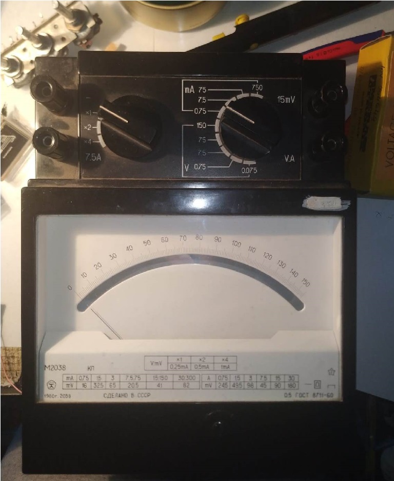
Its internal resistance, measured on this range (0,75ma x1) with a multimeter is 21,7ohms

Connecting the meter to the circuit (no pot/resistor in series) and shorting the probes, I get a reading of exactly 70, multiplying by 5 -> 350uA

Measuring the voltage on the terminals of the voltammeter: 0,007V

The ESR deflection on the linear scale of the voltammeter is the same as yours:

Your meter deflection (taken from page 1):
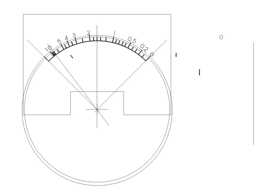


Notice that the 2 ohm inscription is on the left side of the middle line.

The voltammeter deflection is the same as above, if I connect a 2 ohm load across the probes of the circuit, it shows 32 -> 160 uA, that's right below 175uA (half of 350uA).

But I got issues when I use a VU meter.

I don't think that the circuit is the problem, because when connecting the voltammeter, that has a linear scale, the deflection is the same as yours.

The VU meters:


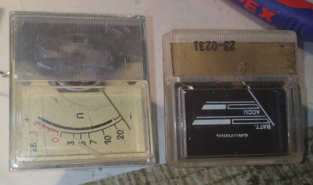
They both have the same "problem".
 
I don't think it's a problem, maybe is something that vu meters do, and maybe you guys know:

So, I connected the meter circuit as below:


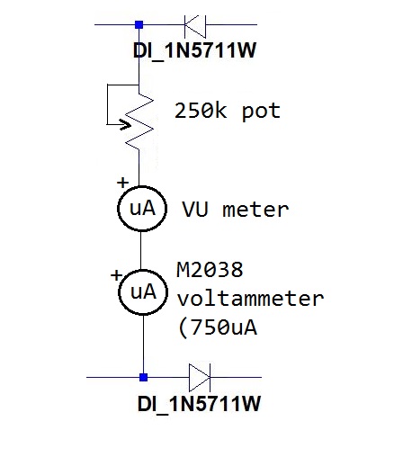
With the help of the 250k pot, I can adjust/peak the needle of the VU meter, and the voltammeter offers a precise reading of the current passing thru the VU meter.

So I peaked the VU meter (capacitor probes shorted):
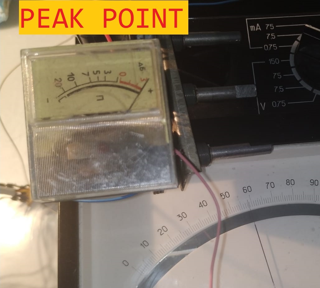


I get a reading of 57,5 -> 287,5uA, let s call this the full deflection point.

Logically, the mid point will be at 57,5/2= 28,75 -> 143,7uA

I adjusted the pot so I can get the needle right in the middle:


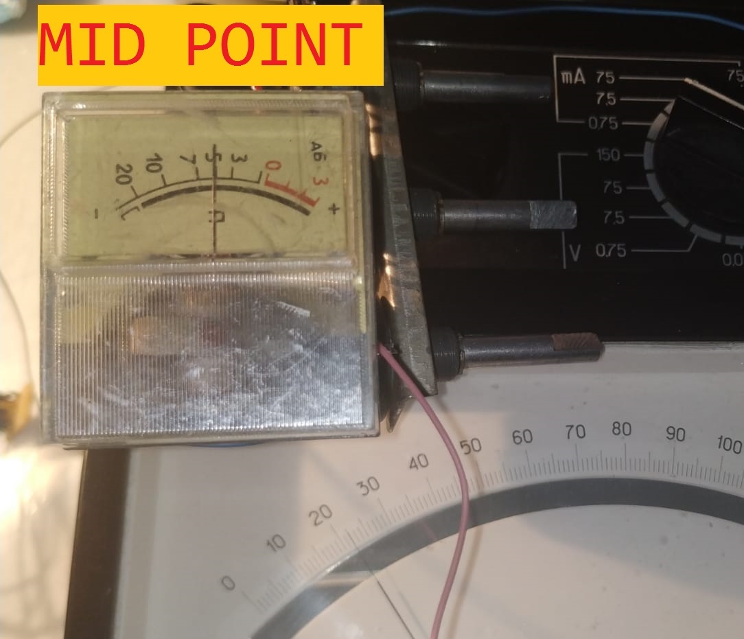
BUT I get a reading of 22 -> 110uA.

This means that the mid point is shifted 33uA below what it should be (110ua instead of 143ua) and the delflection on the VU meter would look like this:


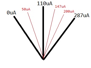
The left side (the higher ESR values) have more space on the scale than the ones on the right side (the lower ESR values). This makes the reading of low ESR values harder, that is a little of a problem.

At the beginning, I mentioned that a 2 ohm reading will be at the left side of the scale.
If I connect a 2 ohm resistance at the capacitor probes:


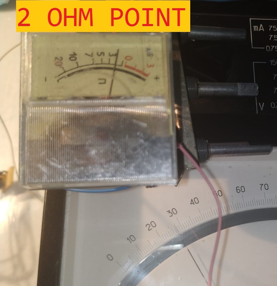
See, the needle is in the right side of the scale...

Why is it so? Are the VU meters not linear?  I get the exact same problem with the black grundig vu meter, the mid point is not at the half of the full curent deflection.

Thanks!
« Last Edit: June 04, 2019, 10:04:50 pm by Richard9026 »
 

Offline cpt.armadillo

  • Newbie
  • Posts: 2
  • Country: us
Re: 5 Transistor ESR Meter Design
« Reply #231 on: June 05, 2019, 09:18:25 pm »
From https://en.wikipedia.org/wiki/VU_meter, it looks like it is not going to act linearly like a simple ammeter or voltmeter. I won't pretend to understand it but audio stuff often ends up using dB scales.
 

Offline Jay_Diddy_BTopic starter

  • Super Contributor
  • ***
  • Posts: 2733
  • Country: ca
Re: 5 Transistor ESR Meter Design
« Reply #232 on: June 06, 2019, 02:12:44 am »

snip ...

Why is it so? Are the VU meters not linear?  I get the exact same problem with the black grundig vu meter, the mid point is not at the half of the full curent deflection.

Thanks!

I am not sure about the VU Meters. They are certainly not precision instruments.

It is possible that they are non-linear.

You will have to make a custom scale.

Have a look at this message:

https://www.eevblog.com/forum/projects/5-transistor-esr-meter-design/msg172109/#msg172109

Regards,
Jay_Diddy_B
 

Offline m3vuv

  • Super Contributor
  • ***
  • !
  • Posts: 1738
  • Country: gb
Re: 5 Transistor ESR Meter Design
« Reply #233 on: June 19, 2019, 12:04:11 pm »
are these mirrored,well except the silkscreen.
 

Offline kkamel

  • Contributor
  • Posts: 12
  • Country: eg
Re: 5 Transistor ESR Meter Design
« Reply #234 on: July 15, 2019, 07:12:38 am »
Hi Jay_Diddy_B,
Thanks for your excellent work and thanks for sharing it with us.
I did prepare all the components except of course 1N5711, can’t find it at all can I use BAT85 I can scavenge them from an old board?
I have the Multi-Function Tester - TC1 but I need to make in-circuit testing.
Thanks again,
« Last Edit: July 15, 2019, 07:17:24 am by kkamel »
 

Offline m3vuv

  • Super Contributor
  • ***
  • !
  • Posts: 1738
  • Country: gb
Re: 5 Transistor ESR Meter Design
« Reply #235 on: August 12, 2019, 12:23:48 am »
seems very odd to me, how so many have supposedly built this and had it work before the routing mistake was spotted!!!!
 

Offline m3vuv

  • Super Contributor
  • ***
  • !
  • Posts: 1738
  • Country: gb
Re: 5 Transistor ESR Meter Design
« Reply #236 on: August 12, 2019, 04:51:10 pm »
hi all,ive built this but have no meter movement,any ideas?,would send some scope pics but cant a my scope just died!,its oscillating at 80khz ,so that parts ok,the meter movement checks out ok,ive took some pic of variouse voltages,hope they display ok,find attached,any pointers on what wrong?,cheers paul.
 

Offline m3vuv

  • Super Contributor
  • ***
  • !
  • Posts: 1738
  • Country: gb
Re: 5 Transistor ESR Meter Design
« Reply #237 on: August 12, 2019, 04:52:47 pm »
meant to say in my last post the readings were with the test points open.
 

Offline m3vuv

  • Super Contributor
  • ***
  • !
  • Posts: 1738
  • Country: gb
Re: 5 Transistor ESR Meter Design
« Reply #238 on: August 14, 2019, 09:35:14 am »
anyone help ?
 

Offline Cliff Matthews

  • Supporter
  • ****
  • Posts: 1910
  • Country: ca
    • General Repair and Support
Re: 5 Transistor ESR Meter Design
« Reply #239 on: August 16, 2019, 01:56:15 pm »
anyone help ?
You've posted on the forum 173 times, you should know jpg files can be uploaded..  |O

If by chance, you didn't have a free image program like IrfanView, I'll post the the useful one.
 

Offline m3vuv

  • Super Contributor
  • ***
  • !
  • Posts: 1738
  • Country: gb
Re: 5 Transistor ESR Meter Design
« Reply #240 on: August 17, 2019, 03:03:26 pm »
thanks for that,i didnt know about the files,ive attached the pic of my various readings,anyone have any idea why its not working?,ps the movement is new and working.
 

Offline m3vuv

  • Super Contributor
  • ***
  • !
  • Posts: 1738
  • Country: gb
Re: 5 Transistor ESR Meter Design
« Reply #241 on: August 19, 2019, 05:57:32 pm »
well ive solved one problem and i have another,when building this i put a linkin place of the 10k pot as ive got mine on the front panel,i had forgot to solder one side of the link,anyway i soldered it,not the meter is hard over to the right with test points open,the only way i can get the meter to read at zero ie left,is by removing c8 22nf,ive checked all the cap values etc,for  c4+c6 im using 100uf electrolytics,any ideas?,cheers m3vuv.
 

Offline m3vuv

  • Super Contributor
  • ***
  • !
  • Posts: 1738
  • Country: gb
Re: 5 Transistor ESR Meter Design
« Reply #242 on: August 20, 2019, 12:57:33 pm »
well it looks like ive found the issue,ive been building this using the design for the pcb from mauroh,in short its a total fuck up,ive traced it thru after building it,the leg of c3 that should go to q4 base,his goes to q5 base and c8 is going to the base of q4 not q5,why to ppl not build there desigh of a pcb before releasing it?,ffs what a fuck up!,lost count of the hours ive spent on this fuck up and wasted copper clad,the cuircuit works well as i built it manhatan style a while ago,just maurohs routing is a
 

Offline m3vuv

  • Super Contributor
  • ***
  • !
  • Posts: 1738
  • Country: gb
Re: 5 Transistor ESR Meter Design
« Reply #243 on: August 20, 2019, 12:59:32 pm »
well it looks like ive found the issue,ive been building this using the design for the pcb from mauroh,in short its a total fuck up,ive traced it thru after building it,the leg of c3 that should go to q4 base,his goes to q5 base and c8 is going to the base of q4 not q5,why to ppl not build there desigh of a pcb before releasing it?,ffs what a fuck up!,lost count of the hours ive spent on this fuck up and wasted copper clad,the cuircuit works well as i built it manhatan style a while ago,just maurohs routing is a fuck up even 2nd time around!
 

Offline bd139

  • Super Contributor
  • ***
  • Posts: 23018
  • Country: gb
Re: 5 Transistor ESR Meter Design
« Reply #244 on: August 20, 2019, 01:05:25 pm »
Joy. At least you got to the bottom of it. Perhaps there should be a warning in this thread.
 

Offline m3vuv

  • Super Contributor
  • ***
  • !
  • Posts: 1738
  • Country: gb
Re: 5 Transistor ESR Meter Design
« Reply #245 on: August 20, 2019, 02:29:59 pm »
makes me laugh at the amount of ppl have built this and supposidly had it work,ive had various attempts at building this over the last few years,it was only today i figured it out,i made it on thin pcb so holding it up to the window could see thr to where the tracks went,supprising its not been spotted before,im just etching jdiddys original,we will see how that fairs!
 

Offline bd139

  • Super Contributor
  • ***
  • Posts: 23018
  • Country: gb
Re: 5 Transistor ESR Meter Design
« Reply #246 on: August 20, 2019, 02:36:50 pm »
This used to be a design feature in some of the old electronics magazines I read when I was a kid :-DD

Think mine only worked because I did it from the schematic rather than the PCB layouts.
 

Offline m3vuv

  • Super Contributor
  • ***
  • !
  • Posts: 1738
  • Country: gb
Re: 5 Transistor ESR Meter Design
« Reply #247 on: August 20, 2019, 04:24:05 pm »
thats the same as my first one was made manhattan style from the schematic.
 

Offline m3vuv

  • Super Contributor
  • ***
  • !
  • Posts: 1738
  • Country: gb
Re: 5 Transistor ESR Meter Design
« Reply #248 on: August 20, 2019, 09:57:56 pm »
Well p diddys pcb worked like a charm strait off,ppl need warning about mauros pcb layout,its plain wrong,cant ever work,wish i had never of seen it with all the time and money wasted!!
 

Offline mauroh

  • Frequent Contributor
  • **
  • Posts: 292
  • Country: it
    • Mauro Pintus
Re: 5 Transistor ESR Meter Design
« Reply #249 on: August 22, 2019, 01:41:28 am »
Dear m3vuv,
    I apologize for the trouble I caused to you and to someone else that used my incorrect files....
Just to understand what happened and to fix further mistakes, can you please tell me which version of my PCB Layout have you used?
The 1.3 that is the latest one should be correct.
There was a trace overlap in the previous versions that was spotted by another forum member on February 2019, see this: https://www.eevblog.com/forum/projects/5-transistor-esr-meter-design/msg2213103/#msg2213103
Please let me know if you have found another issue.
When I uploaded the corrected files, I delated all the previous one from all my posts in this thread and now I'm sure all the files are updated.
Please let me know
Mauro

If you use mauroh PCB Layout, do not use files with version below 1.3. There was a mistake in the routing.

Offline m3vuv

  • Super Contributor
  • ***
  • !
  • Posts: 1738
  • Country: gb
Re: 5 Transistor ESR Meter Design
« Reply #250 on: August 22, 2019, 09:05:50 am »
Hi i used the latest version of your pcb layout,you have the base conections inverted,ie what routes to base of q3 should go to the base of q4 and what goes to the base of q4 should go to q3,regards m3vuv.
 

Offline m3vuv

  • Super Contributor
  • ***
  • !
  • Posts: 1738
  • Country: gb
Re: 5 Transistor ESR Meter Design
« Reply #251 on: August 22, 2019, 03:19:35 pm »
heres some pics of the one i just built,reads slightly high as i need to tweak the meter series resistor.
 

Offline m3vuv

  • Super Contributor
  • ***
  • !
  • Posts: 1738
  • Country: gb
Re: 5 Transistor ESR Meter Design
« Reply #252 on: August 22, 2019, 03:22:12 pm »
not all uploaded.
 

Offline m3vuv

  • Super Contributor
  • ***
  • !
  • Posts: 1738
  • Country: gb
Re: 5 Transistor ESR Meter Design
« Reply #253 on: August 23, 2019, 08:10:10 am »
is there anyway another transistor could be added onto this so it can drive a 1ma fsd meter movement as ive some lovely big meters in cases from the 1960s but all 1ma fsd.,also an add on to check shorted caps maybe?
 

Offline bd139

  • Super Contributor
  • ***
  • Posts: 23018
  • Country: gb
Re: 5 Transistor ESR Meter Design
« Reply #254 on: August 23, 2019, 12:26:39 pm »
I think you'd need a higher supply voltage and much lower impedance at the actual rectifier bridge I reckon before that would be possible. Adding emitter followers after Q4/Q5 might do the trick but I haven't simulated it.

Nice looking build BTW  :-+
 

Offline m3vuv

  • Super Contributor
  • ***
  • !
  • Posts: 1738
  • Country: gb
Re: 5 Transistor ESR Meter Design
« Reply #255 on: August 25, 2019, 11:02:51 am »
your r15 680 is marked as r14 on mine,says 27k originaly,do you have them mixed up?,thats on the high power mod.
 

Offline m3vuv

  • Super Contributor
  • ***
  • !
  • Posts: 1738
  • Country: gb
Re: 5 Transistor ESR Meter Design
« Reply #256 on: August 30, 2019, 10:26:32 am »
whats going on here?,the both schematics seemed to have a mix up with r12 -13-14-15 and 16,both shematics are different also which one corresponds to the thru hole component/silkscreen?,makes it hard work with silly cockups like that,can it be sorted?.cheers paul m3vuv.
 

Offline m3vuv

  • Super Contributor
  • ***
  • !
  • Posts: 1738
  • Country: gb
Re: 5 Transistor ESR Meter Design
« Reply #257 on: September 02, 2019, 01:46:00 pm »
so mr diddy can you explain which schematic corresponds to which silscreen(ie component placement) pic?
 

Offline mauroh

  • Frequent Contributor
  • **
  • Posts: 292
  • Country: it
    • Mauro Pintus
Re: 5 Transistor ESR Meter Design
« Reply #258 on: September 03, 2019, 10:26:05 am »
Hi m3vuv,
   I just played spot the difference for few minutes with the original schematic from Jay_Diddy_B against the one I used to make my PCB routing and I really can't see anything that could prevent my circuit to work.
The DRC is fine and all the traces should go to the coorrect component.
In the silkscreen I privided, on top of the components you have the value of the components to place.
I'm not getting what it is wrong with the schematic or with the PCB and what it is mixed up in the components you have listed.

In few weeks I hope to have the spare time to build it and sort this out.

I have attached the comparison between the schematics.
Please let me know what I'm not seeing.
Thank you
Mauro

Offline m3vuv

  • Super Contributor
  • ***
  • !
  • Posts: 1738
  • Country: gb
Re: 5 Transistor ESR Meter Design
« Reply #259 on: September 03, 2019, 11:30:13 am »
it was the base connections were inverted think it was q4 q5 base connections were swapped,only spotted it as the board was thin and holding it up to the light i could trace the routing,hope that helps.
 

Offline m3vuv

  • Super Contributor
  • ***
  • !
  • Posts: 1738
  • Country: gb
Re: 5 Transistor ESR Meter Design
« Reply #260 on: October 30, 2019, 04:20:38 am »
seems to have died a death,still looking to use it with a 1ma fsd meter,any ideas how to do this?,cheers all m3vuv.
 

Offline X.G.

  • Newbie
  • Posts: 5
  • Country: cn
Re: 5 Transistor ESR Meter Design
« Reply #261 on: April 01, 2020, 07:45:20 am »
« Last Edit: April 01, 2020, 08:02:59 am by X.G. »
 
The following users thanked this post: bitseeker, bd139

Offline m3vuv

  • Super Contributor
  • ***
  • !
  • Posts: 1738
  • Country: gb
Re: 5 Transistor ESR Meter Design
« Reply #262 on: April 01, 2020, 08:56:15 am »
still no solutions to use a 1ma fsd meter movement yet then?
 

Offline X.G.

  • Newbie
  • Posts: 5
  • Country: cn
Re: 5 Transistor ESR Meter Design
« Reply #263 on: April 01, 2020, 09:16:25 am »
another ESR meter design from China.it (and mine) can use the anologe  multimeter scale,and only use one IC.

TDA1308 can work at 3V~5V ,so you can use Li-rechargeble battery for it. if you have not TDA1308,you can use NE5532 at 7V~9V

R7=the centre value of scale,R5=R6=2*R7

http://www.crystalradio.cn/forum.php?mod=viewthread&tid=511567&extra=&page=1

« Last Edit: April 01, 2020, 09:27:48 am by X.G. »
 
The following users thanked this post: bitseeker, bd139

Offline m3vuv

  • Super Contributor
  • ***
  • !
  • Posts: 1738
  • Country: gb
Re: 5 Transistor ESR Meter Design
« Reply #264 on: April 09, 2020, 06:26:52 pm »
please someone mod the circuit to make this good to work with a 1ma fsd meter movement,or mod the schematic for me please,im lost on doing this.,cheers m3vuv.
 

Offline Jay_Diddy_BTopic starter

  • Super Contributor
  • ***
  • Posts: 2733
  • Country: ca
Re: 5 Transistor ESR Meter Design
« Reply #265 on: April 10, 2020, 11:36:50 am »
Hi M3VUV and the group,

Here is a simulation for using a 1mA meter movement.

I have not built this circuit - it is experimental - try at your own risk
Report your results


Model


There are notes on the model regarding component selection.

Modelling Results


The modelling results suggest that this should work.

If this doesn't work look for a more sensitive meter.
Most analog VOM or AVO that 20,000 \$\Omega\$ per volt have 50uA movements.

Regards,

Jay_Diddy_B

 
The following users thanked this post: Cliff Matthews, bd139

Offline m3vuv

  • Super Contributor
  • ***
  • !
  • Posts: 1738
  • Country: gb
Re: 5 Transistor ESR Meter Design
« Reply #266 on: April 10, 2020, 12:28:26 pm »
cheers i will give it a try.
 

Offline m3vuv

  • Super Contributor
  • ***
  • !
  • Posts: 1738
  • Country: gb
Re: 5 Transistor ESR Meter Design
« Reply #267 on: April 11, 2020, 11:09:58 am »
Hi jay nice work,can i assume this can be used with your tonner transfer pdf by subing the comp values?,cheers m3vuv.
 

Offline Jay_Diddy_BTopic starter

  • Super Contributor
  • ***
  • Posts: 2733
  • Country: ca
Re: 5 Transistor ESR Meter Design
« Reply #268 on: April 11, 2020, 12:23:26 pm »
Hi jay nice work,can i assume this can be used with your tonner transfer pdf by subing the comp values?,cheers m3vuv.

Yes, build it using the same artwork.

Build it like this one:

https://www.eevblog.com/forum/projects/5-transistor-esr-meter-design/msg2635062/#msg2635062

Just change the component values.

Regards,
Jay_Diddy_B
 
The following users thanked this post: Cliff Matthews

Offline m3vuv

  • Super Contributor
  • ***
  • !
  • Posts: 1738
  • Country: gb
Re: 5 Transistor ESR Meter Design
« Reply #269 on: April 12, 2020, 04:07:04 pm »
can this silscreen art be posted as a jpeg?,otherwise its a twat to scale when printing,cheers m3vuv.
 

Offline Jay_Diddy_BTopic starter

  • Super Contributor
  • ***
  • Posts: 2733
  • Country: ca
Re: 5 Transistor ESR Meter Design
« Reply #270 on: April 12, 2020, 05:44:28 pm »
can this silscreen art be posted as a jpeg?,otherwise its a twat to scale when printing,cheers m3vuv.

Hi,

There are two jpeg. One is mirrored in case you want to do toner transfer.

Jay_Diddy_B
 

Offline m3vuv

  • Super Contributor
  • ***
  • !
  • Posts: 1738
  • Country: gb
Re: 5 Transistor ESR Meter Design
« Reply #271 on: April 12, 2020, 07:50:04 pm »
sorry i cocked up,meant to say pdf,regards m3vuv
 

Offline Jay_Diddy_BTopic starter

  • Super Contributor
  • ***
  • Posts: 2733
  • Country: ca
Re: 5 Transistor ESR Meter Design
« Reply #272 on: April 12, 2020, 08:22:09 pm »
sorry i cocked up,meant to say pdf,regards m3vuv

Here you go...

Regards,
Jay_Diddy_B
 

Offline m3vuv

  • Super Contributor
  • ***
  • !
  • Posts: 1738
  • Country: gb
Re: 5 Transistor ESR Meter Design
« Reply #273 on: April 13, 2020, 09:13:28 am »
Many thanks jay.73 m3vuv.
 

Offline m3vuv

  • Super Contributor
  • ***
  • !
  • Posts: 1738
  • Country: gb
Re: 5 Transistor ESR Meter Design
« Reply #274 on: April 13, 2020, 05:53:38 pm »
have you this version in pdf as well,as it shows the track routing,cheers Paul m3vuv
 

Offline Jay_Diddy_BTopic starter

  • Super Contributor
  • ***
  • Posts: 2733
  • Country: ca
Re: 5 Transistor ESR Meter Design
« Reply #275 on: April 13, 2020, 06:16:32 pm »
have you this version in pdf as well,as it shows the track routing,cheers Paul m3vuv

See attached.

Regards,
Jay_Diddy_B
 

Offline m3vuv

  • Super Contributor
  • ***
  • !
  • Posts: 1738
  • Country: gb
Re: 5 Transistor ESR Meter Design
« Reply #276 on: April 13, 2020, 07:52:10 pm »
whats with c2 and r11?
 

Offline Jay_Diddy_BTopic starter

  • Super Contributor
  • ***
  • Posts: 2733
  • Country: ca
Re: 5 Transistor ESR Meter Design
« Reply #277 on: April 13, 2020, 09:26:00 pm »
whats with c2 and r11?

I assume that you are asking about these parts in the LTspice model?


They represent the capacitor being tested.

DUT = device under test

TP1 and TP2 on the hardware schematic.

Regards,
Jay_Diddy_B
« Last Edit: April 13, 2020, 09:28:16 pm by Jay_Diddy_B »
 
The following users thanked this post: Cliff Matthews

Offline m3vuv

  • Super Contributor
  • ***
  • !
  • Posts: 1738
  • Country: gb
Re: 5 Transistor ESR Meter Design
« Reply #278 on: April 17, 2020, 12:50:46 pm »
but the marking for c2 on the silkscreen is for a cap not the test points,it is on the artwork anyway,tp 1+2 are on the oposite side of the board,so what do i fit in the markings for c2 on my pcb?
 

Offline m3vuv

  • Super Contributor
  • ***
  • !
  • Posts: 1738
  • Country: gb
Re: 5 Transistor ESR Meter Design
« Reply #279 on: April 17, 2020, 12:54:33 pm »
also i dont see c9 or 10 on the schematic.but they are on the silkscreen.getting confusing!.
 

Offline m3vuv

  • Super Contributor
  • ***
  • !
  • Posts: 1738
  • Country: gb
Re: 5 Transistor ESR Meter Design
« Reply #280 on: April 17, 2020, 05:08:28 pm »
should c2 on the silkscreen not be c1? on the schematic??
 

Offline Jay_Diddy_BTopic starter

  • Super Contributor
  • ***
  • Posts: 2733
  • Country: ca
Re: 5 Transistor ESR Meter Design
« Reply #281 on: April 17, 2020, 07:13:52 pm »
Hi M3VUV,

You missed this note on the drawing:


To make it easier for you have attached a pdf schematic with the changes for the 1mA meter movement. This is a hardware schematic and matches the board layout that I shared.

Regards,
Jay_Diddy_B
 
The following users thanked this post: Cliff Matthews

Offline m3vuv

  • Super Contributor
  • ***
  • !
  • Posts: 1738
  • Country: gb
Re: 5 Transistor ESR Meter Design
« Reply #282 on: April 17, 2020, 07:39:01 pm »
 jay,that makes sense now!,cheers Paul 73.
 

Offline roydc2010

  • Newbie
  • Posts: 3
  • Country: us
Re: 5 Transistor ESR Meter Design
« Reply #283 on: April 26, 2020, 12:06:01 am »
Hello Everyone,
I really like this meter and have been attempting to build one. I used a PCB layout from 5QESR.  Q2-Q5 are wrong on the silkscreen. The flat part of the transistors should be turned 180 degrees from what the silkscreen says. I put everything together and with the input terminals open circuit, the meter deflects to the right about 3/4 scale. It should stay to the right and deflect all the way left when shorted.

I saw J_Diddy_5 posted voltages and oscilloscope shots at various points in the circuit for troubleshooting so I measured these same locations. Here are my results:
Q3 Collector V = 2.52V
TP1 =                103mV pk-pk
Q3 Base V =       4.65V
Q4 Base V =       1.30V
Q4 Collector V = 2.64V
Q5 Base V =       1.30V
Q5 Collector V = 2.73V

For R24 the pot I am using a 50k ohm and it is set at the top of 50k ohm. Moving it lower makes the meter deflect further to the right with the test points open circuit. I see most people are using around 10-20k ohms.

I scoped the base of Q4 and Q5 and they are reading equal when inputs are open circuit.
D1 and D2 are UF4007
D3 and D4 are 1N5711
All caps are ceramic. C2 (oscillator cap) is 1.5nF +-5%. Should this be a tighter tolerance?

 
« Last Edit: April 26, 2020, 12:39:31 am by roydc2010 »
 

Offline Jay_Diddy_BTopic starter

  • Super Contributor
  • ***
  • Posts: 2733
  • Country: ca
Re: 5 Transistor ESR Meter Design
« Reply #284 on: April 26, 2020, 01:05:29 am »
Hello Everyone,
I really like this meter and have been attempting to build one. I used a PCB layout from 5QESR.  Q2-Q5 are wrong on the silkscreen.

Snip ...
 

Paul M6KUR used European Transistor when he designed his variation of the my circuit.

He used BC547 for the NPN transistors

and BC557 for the PNP transistors.

Both are in the same package, TO-92

The layout given by Paul in the 5QESR is correct for the BC547 and BC557 transistors.

The original layout is correct for the North American 2N3904 and 2N3906 transistors.


All the transistors, Q1 - Q5 should be 'wrong'.

Regards,
Jay_Diddy_B


Offline Jay_Diddy_BTopic starter

  • Super Contributor
  • ***
  • Posts: 2733
  • Country: ca
Re: 5 Transistor ESR Meter Design
« Reply #285 on: April 26, 2020, 01:19:13 am »
I put everything together and with the input terminals open circuit, the meter deflects to the right about 3/4 scale. It should stay to the right and deflect all the way left when shorted.

I saw J_Diddy_5 posted voltages and oscilloscope shots at various points in the circuit for troubleshooting so I measured these same locations. Here are my results:
Q3 Collector V = 2.52V
TP1 =                103mV pk-pk
Q3 Base V =       4.65V
Q4 Base V =       1.30V
Q4 Collector V = 2.64V
Q5 Base V =       1.30V
Q5 Collector V = 2.73V

For R24 the pot I am using a 50k ohm and it is set at the top of 50k ohm. Moving it lower makes the meter deflect further to the right with the test points open circuit. I see most people are using around 10-20k ohms.

I scoped the base of Q4 and Q5 and they are reading equal when inputs are open circuit.
D1 and D2 are UF4007
D3 and D4 are 1N5711
All caps are ceramic. C2 (oscillator cap) is 1.5nF +-5%. Should this be a tighter tolerance?


The component selection is okay.
5% tolerance on the capacitor is okay.

The DC voltages are all okay. This means the transistors Q4 and Q5 are biased correctly.

The meter reading is impacted by the shorting TP1 to TP2. This means C3 and C7 are there.

Check

R11, R12, C8

R20 and C6

If you have a scope look at Q5 collector voltage.

Regards,
Jay_Diddy_B
 

Offline roydc2010

  • Newbie
  • Posts: 3
  • Country: us
Re: 5 Transistor ESR Meter Design
« Reply #286 on: April 27, 2020, 11:59:10 pm »
Thanks J_Diddy_B,

I didn't realize the emitter and collector were switched between the BC547 and the 2N3904. Still the layout of Q1 for a 2N3904 I thought was correct.
Collector connects to the high/+ and emitter connects to the low/- correct? Here is a picture of my board. I'm using 2N3904 (Q1,Q2,Q4,Q5) and 2N3906 (Q3).

I verified the resistors and caps you suggested and scoped Q5 collector:
R11 = 1.46k \$\Omega\$
R12 = 29.9 \$\Omega\$
R20 = 32.7 \$\Omega\$
C6 =   2.3 microF
C8 =   21.8nF
Q5 Collector = 3.04 V pk-pk

Thanks,
Dave
« Last Edit: April 28, 2020, 12:02:51 am by roydc2010 »
 

Offline Jay_Diddy_BTopic starter

  • Super Contributor
  • ***
  • Posts: 2733
  • Country: ca
Re: 5 Transistor ESR Meter Design
« Reply #287 on: April 28, 2020, 01:20:55 am »
Hi,

There is a mistake in the layout shared by Paul.

The negative side of the meter is connected to ground in his layout.

It should be connected to Anode of D4

5QESR Schematic - This is correct


5QESR Board - wrong


The negative end of the meter is connected to ground.

Disconnect from ground and connect to D4 Anode.


Let us know if this helps.

Is EasyEDA that bad, that allows the netlist of the board not match the schematic? Most half decent CAD systems won't allow this.

Regards,
Jay_Diddy_B
« Last Edit: April 28, 2020, 01:22:42 am by Jay_Diddy_B »
 

Offline roydc2010

  • Newbie
  • Posts: 3
  • Country: us
Re: 5 Transistor ESR Meter Design
« Reply #288 on: April 29, 2020, 12:21:41 pm »
You were correct. I attached the negative side of the meter to the anode of D4 and it works great. It was my first time using EasyEDA. I just used the files 5QESR had available. A nice learning experience for me. Thanks for your help.
 

Offline m3vuv

  • Super Contributor
  • ***
  • !
  • Posts: 1738
  • Country: gb
Re: 5 Transistor ESR Meter Design
« Reply #289 on: August 19, 2020, 07:38:46 pm »
Hi all,ive just built the version of this using the 1ma meter movement,strange thing is with the test probes open it reads 3/4 scale to the right,when the test probes are shorted it goes fully to the left,any ideas?,cheers in advance.m3vuv.
 

Offline Jay_Diddy_BTopic starter

  • Super Contributor
  • ***
  • Posts: 2733
  • Country: ca
Re: 5 Transistor ESR Meter Design
« Reply #290 on: August 19, 2020, 08:38:58 pm »
Hi,

It sounds like one of the two amplifiers  on each side of the meter is working properly.

Follow the procedure that starts here:

https://www.eevblog.com/forum/projects/5-transistor-esr-meter-design/200/

Start by looking at the DC voltages in the circuit. The voltages for the 1mA circuit should similar.

Then check the capacitors.


Jay_Diddy_B
 

Offline m3vuv

  • Super Contributor
  • ***
  • !
  • Posts: 1738
  • Country: gb
Re: 5 Transistor ESR Meter Design
« Reply #291 on: August 20, 2020, 10:07:51 am »
well the voltages measure the following left to right (output from 7805=4,25),q2 collector=3.8v,q3 collector=2.08v,q4 base =1.02v,q4 collector= 3.03v,q5 collector=2.64v,q5 base=3,3v,all the caps seem ok apart from c2 thats 1.8nf,hope this helps,cheers m3vuv.
 

Offline Jay_Diddy_BTopic starter

  • Super Contributor
  • ***
  • Posts: 2733
  • Country: ca
Re: 5 Transistor ESR Meter Design
« Reply #292 on: August 20, 2020, 12:55:21 pm »
Hi M3VUV,

Check the resistor in the emitter of Q5, R19. It should be 68 \$\Omega\$

Why is the output of the 7805 only 4.25V? it should be 5V.

What is the input to the 7805?

Is the 7805 getting warm?

Regards,
Jay_Diddy_B
 

Offline m3vuv

  • Super Contributor
  • ***
  • !
  • Posts: 1738
  • Country: gb
Re: 5 Transistor ESR Meter Design
« Reply #293 on: August 20, 2020, 01:35:51 pm »
the input to the 7805 is 12v from a iinear psu,the reg is from china so suspect a reject/fake.
 

Offline m3vuv

  • Super Contributor
  • ***
  • !
  • Posts: 1738
  • Country: gb
Re: 5 Transistor ESR Meter Design
« Reply #294 on: August 20, 2020, 01:45:30 pm »
r19 is bang on 68 ohm.
 

Offline Jay_Diddy_BTopic starter

  • Super Contributor
  • ***
  • Posts: 2733
  • Country: ca
Re: 5 Transistor ESR Meter Design
« Reply #295 on: August 20, 2020, 03:05:20 pm »
Hi,
Check or replace Q5.

Check R21 and R22.

The voltage on Q5 base should be 1.3V


The DC voltages in the Q4 and Q5 circuits should be the same. They are very similar circuits.


Jay_Diddy_B
« Last Edit: August 20, 2020, 03:09:26 pm by Jay_Diddy_B »
 

Offline m3vuv

  • Super Contributor
  • ***
  • !
  • Posts: 1738
  • Country: gb
Re: 5 Transistor ESR Meter Design
« Reply #296 on: August 20, 2020, 05:37:33 pm »
well somehow i had a 30 ohm in place of r21,ive fitted a 27k,it seems to work but i can only get about %50 meter deflection with the probes shorted,thats also with r24 shorted also,any idears,its like the meter needs more drive,cheers m3vuv.
 

Offline m3vuv

  • Super Contributor
  • ***
  • !
  • Posts: 1738
  • Country: gb
Re: 5 Transistor ESR Meter Design
« Reply #297 on: August 21, 2020, 07:27:28 am »
would lowering the value of r15 and r19 give me more meter drive?,the 7805 runs cool,what if i used a 8volt reg would that help and run it from 2x pp3 ie 18v?
 

Offline m3vuv

  • Super Contributor
  • ***
  • !
  • Posts: 1738
  • Country: gb
Re: 5 Transistor ESR Meter Design
« Reply #298 on: August 21, 2020, 05:37:39 pm »
Well,ive sorted it,i lfted the ground of the regulator and added an led + a 1n5711 schottky diode between that and ground(shall use the led as an on indicator later)that lifted the 7805 output to about 7.1v,now the meter will go full scale,and i get 125 milivolt at the test probes so still good for in circuit testing,im running it from a 3s 3p lion 18650 battery pack thats 7.2 ah so should last a while on a charge,will upload some pics soon,it reads about %10 low but thats as near as dam it for me!,cheers jay 73 m3vuv.
 

Offline m3vuv

  • Super Contributor
  • ***
  • !
  • Posts: 1738
  • Country: gb
Re: 5 Transistor ESR Meter Design
« Reply #299 on: August 21, 2020, 05:45:01 pm »
a few pics
 
The following users thanked this post: bd139

Offline m3vuv

  • Super Contributor
  • ***
  • !
  • Posts: 1738
  • Country: gb
Re: 5 Transistor ESR Meter Design
« Reply #300 on: August 21, 2020, 05:47:50 pm »
measuring a 3r9 resistor
 

Offline m3vuv

  • Super Contributor
  • ***
  • !
  • Posts: 1738
  • Country: gb
Re: 5 Transistor ESR Meter Design
« Reply #301 on: August 21, 2020, 05:49:36 pm »
measuring a 1.1 ohm resistor
 

Offline m3vuv

  • Super Contributor
  • ***
  • !
  • Posts: 1738
  • Country: gb
Re: 5 Transistor ESR Meter Design
« Reply #302 on: August 21, 2020, 06:23:20 pm »
few pics of the guts of it.
 

Offline m3vuv

  • Super Contributor
  • ***
  • !
  • Posts: 1738
  • Country: gb
Re: 5 Transistor ESR Meter Design
« Reply #303 on: August 21, 2020, 06:27:22 pm »
final pic
 

Offline bd139

  • Super Contributor
  • ***
  • Posts: 23018
  • Country: gb
Re: 5 Transistor ESR Meter Design
« Reply #304 on: August 21, 2020, 06:58:10 pm »
Nice work. Also good use for those horrid Bradley meters  :-DD. Thumbs up here  :-+
 

Offline m3vuv

  • Super Contributor
  • ***
  • !
  • Posts: 1738
  • Country: gb
Re: 5 Transistor ESR Meter Design
« Reply #305 on: August 21, 2020, 09:15:35 pm »
thats what i thought,i brought 5 of those meters from j,birketts in lincoln for £5 a pop,absolute baskets to work on so gave up,handy for the meter movements tho.
 

Offline bd139

  • Super Contributor
  • ***
  • Posts: 23018
  • Country: gb
Re: 5 Transistor ESR Meter Design
« Reply #306 on: August 21, 2020, 09:18:32 pm »
Wow is he still around? I went in there probably 20 years ago now purely by accident after driving past and it looked interesting. Came out with a whole box of crap and an angry and hot girlfriend  :-DD
 

Offline m3vuv

  • Super Contributor
  • ***
  • !
  • Posts: 1738
  • Country: gb
Re: 5 Transistor ESR Meter Design
« Reply #307 on: August 22, 2020, 09:42:58 am »
Yes he is still going,i was in there chatting with him a few months ago,he is over 90yrs old now,still sharp as a needle tho,i was asking about collins 318t radios,said he had a load but brought them from the raf and sold them all to the army,interesting fella,just as deaf as a post!.
 
The following users thanked this post: bd139

Offline m3vuv

  • Super Contributor
  • ***
  • !
  • Posts: 1738
  • Country: gb
Re: 5 Transistor ESR Meter Design
« Reply #308 on: August 23, 2020, 06:34:52 pm »
just found a .1 ohm .5% resistor to measure,sort of taken back how well it reads such low values,the big meter scale makes it so easy to read,this ones a keeper!
 
The following users thanked this post: bd139

Offline bitseeker

  • Super Contributor
  • ***
  • Posts: 9057
  • Country: us
  • Lots of engineer-tweakable parts inside!
Re: 5 Transistor ESR Meter Design
« Reply #309 on: August 23, 2020, 07:34:56 pm »
And the "Lethal Warning" label adds a little extra something to it. ;D
TEA is the way. | TEA Time channel
 

Offline m3vuv

  • Super Contributor
  • ***
  • !
  • Posts: 1738
  • Country: gb
Re: 5 Transistor ESR Meter Design
« Reply #310 on: August 29, 2020, 03:00:29 pm »
mr diddy,is there anyway i can run this from a pp3 9v battery,just less hassle than lithium ion batterys with the associated bms etc for charging,a single pp3 would be better,cheers m3vuv.
 

Offline rogerggbr

  • Newbie
  • Posts: 9
  • Country: gb
Re: 5 Transistor ESR Meter Design
« Reply #311 on: October 23, 2020, 06:18:44 pm »
Just like to add my thanks to Jay_Diddy_B for the original design and all the posts above which helped. I used vero board, a spare box and bought a new meter. Just need to tidy up and label up properly but works really well at those low ranges. 1095846-01095850-1
 
The following users thanked this post: bd139, battlecoder

Offline Jay_Diddy_BTopic starter

  • Super Contributor
  • ***
  • Posts: 2733
  • Country: ca
Re: 5 Transistor ESR Meter Design
« Reply #312 on: October 23, 2020, 07:54:45 pm »
rogerggbr,

First of all welcome to the EEVBlog forum!!

and thank you for the kind words and sharing the pictures of the ESR meter that you built.

( I see from your profile that you are from West Yorkshire. I originate from South Yorkshire, but that was a long time ago).

Regards,
Jay_Diddy_B
 
The following users thanked this post: rogerggbr

Offline battlecoder

  • Regular Contributor
  • *
  • Posts: 156
  • Country: cl
    • A BIT of Mystery
Re: 5 Transistor ESR Meter Design
« Reply #313 on: October 23, 2020, 08:50:55 pm »
Just like to add my thanks to Jay_Diddy_B for the original design and all the posts above which helped. I used vero board, a spare box and bought a new meter. Just need to tidy up and label up properly but works really well at those low ranges. (Attachment Link) (Attachment Link)
I have to admit I like coming back to this thread to see the builds from the community, so thanks for sharing yours, @rogerggbr!

I *really* like this circuit. It's so elegantly simple, and works really well, so thanks again @Jay_Diddy_B for the awesome contribution. Even when I got an LCR meter (that can do ESR) after I built mine, I always check the result against your device.
 
The following users thanked this post: rogerggbr

Offline zoltanh

  • Contributor
  • Posts: 38
  • Country: ro
Re: 5 Transistor ESR Meter Design
« Reply #314 on: November 15, 2020, 11:49:58 am »
Hi,

Greetings from Romania. I built the ESR meter and I would say it is great. However, the microA of 50microA I have is a small one. I have another one of 250 microA and one of 500 microA, both with reasonable size. I built the 250 microA ESR and 1 mA ESR but both of them do not get out more than 150 microA. I checked everything, voltages, signals' levels and forms on oscilloscope and everything it seems to be in line with all available info herein.
Is here somebody who built any of these two variants, 250  microA or 1 mA ? If yes, could you share to me what level of current (maximum deflection) he obtained and eventually what components values he put it or any advice as I do not understand what is wrong with mine? I suspect something is wrong with amplification factor but could not figure out what or why.
I apologize for my ignorance and thank you for help.
 

Offline kripton2035

  • Super Contributor
  • ***
  • Posts: 2581
  • Country: fr
    • kripton2035 schematics repository
Re: 5 Transistor ESR Meter Design
« Reply #315 on: November 15, 2020, 12:25:09 pm »
did you try the other variant of the esr meter, made by the same author.
see here : https://www.eevblog.com/forum/projects/esr-meter-adapter-design-and-construction/
it has the advantage of beeing more robust to charged capacitors, and to output to any voltmeter (or your multimeter)
so that you can use any voltmeter you want, analog or digital.
 

Offline zoltanh

  • Contributor
  • Posts: 38
  • Country: ro
Re: 5 Transistor ESR Meter Design
« Reply #316 on: November 15, 2020, 06:37:05 pm »
Hi,

Thank you for reply.
I did not try it. I prepared the pcb and passive components. Unfortunately, I do not have the CIs. I am looking to find out a source at reasonable price for my budget.
However, I would like to finish the build of either 250 microA or 1 mA. Unfortunaley, I do not know what I miss or mistake there. Therefore, I am interested if somebody built any of them and what he can advise me about.
 

Offline Jay_Diddy_BTopic starter

  • Super Contributor
  • ***
  • Posts: 2733
  • Country: ca
Re: 5 Transistor ESR Meter Design
« Reply #317 on: November 16, 2020, 11:57:50 am »
Hi,

Thank you for reply.
I did not try it. I prepared the pcb and passive components. Unfortunately, I do not have the CIs. I am looking to find out a source at reasonable price for my budget.
However, I would like to finish the build of either 250 microA or 1 mA. Unfortunaley, I do not know what I miss or mistake there. Therefore, I am interested if somebody built any of them and what he can advise me about.

Hi zoltanh and the group,


250uA

The discussion on using a 250uA meter starts at reply 227 here:

https://www.eevblog.com/forum/projects/5-transistor-esr-meter-design/msg2456304/#msg2456304

I gave forum member Richard9026 the modifications that are required. He built a meter using these changes.

In reply 229 Richard9026 reported that these modifications worked.

1mA

There have been repeated requests for a version that uses a 1mA meter. This is not as easy to do. The current required is 20x the original design.

Link: https://www.eevblog.com/forum/projects/5-transistor-esr-meter-design/msg3008380/#msg3008380

In reply 265 I shared an LTspice that shows the modification required for a 1mA version. I have never built this version.
Forum member M3VUV built the 1mA version. In reply 289 M3VUV reported:

Hi all,ive just built the version of this using the 1ma meter movement,strange thing is with the test probes open it reads 3/4 scale to the right,when the test probes are shorted it goes fully to the left,any ideas?,cheers in advance.m3vuv.

In reply 298 M3VUV reported:

Well,ive sorted it,i lfted the ground of the regulator and added an led + a 1n5711 schottky diode between that and ground(shall use the led as an on indicator later)that lifted the 7805 output to about 7.1v,now the meter will go full scale,and i get 125 milivolt at the test probes so still good for in circuit testing,im running it from a 3s 3p lion 18650 battery pack thats 7.2 ah so should last a while on a charge,will upload some pics soon,it reads about %10 low but thats as near as dam it for me!,cheers jay 73 m3vuv.

In short, the 1mA circuit works if you increase the voltage from 5V to 7V.

I have not investigated this.

Regards,
Jay_Diddy_B

 
The following users thanked this post: Cliff Matthews

Offline zoltanh

  • Contributor
  • Posts: 38
  • Country: ro
Re: 5 Transistor ESR Meter Design
« Reply #318 on: November 16, 2020, 07:45:19 pm »
Hi,

Thank you very much for taking the time to reply to my messages.
I have read all the posts of this subject at least three times each, hoping that I missed something which to help me to figure out what is not ok.
As I said I succeeded to build and to get it works for 50 microA variant and up to 150 microA (actually, it was 147 microA) with both variants 250 microA and 1 mA schematics but I could not get higher deflection, amperage.
I tried also to increase the voltage supply. Sadly, I could not increase the output current value above mentioned level, and actually increasing the voltage supply above 7V decreased the deflection to around 110-104 microA.
I prepared other two THT PCBs and one smd PCB and my intention is to build one 250 microA THT, 1 mA THT and 1 mA SMD and see if I can get at least 250 microA. I pretty sure your simulations are fine and something is wrong with my PCBAs but I have no clue what it could be.
I would appreciate any advice as I do not have any idea what to check more and eventually what to experiment (I did not mention before that I did several trials with different values of resistors and capacitors in emitter/collector of Q3, Q4 and Q5 but w/o success).

Thank you.
 

Offline zoltanh

  • Contributor
  • Posts: 38
  • Country: ro
Re: 5 Transistor ESR Meter Design
« Reply #319 on: November 26, 2020, 10:00:17 pm »
Hi,

I finished a new one PCBA, version 1 mA. This is the circuit diagram from #265 which means 60/6 ohms resistors in collector of Q3. I checked/measured each component and I would say the measured values with UNIT-T 139C are almost identical with the values in the circuit diagram. The transistors have beta higher than 400. The PCBA did not reach 1mA but it reaches close. It means 800 microA.
Anyway, still I have a problem. I made a scaled scale, keeping aspect ratio, of scale published by Jay_Diddy_B. Now, on this scale, the deflection in first half of the scale is half of the printed values. In the second half the proportion is not kept anymore and close to the left end of the scale the ratio is 2/3. As the scale is keeping the aspect ratio I expected to have same deflections for same resistance values.
I did not continue and I gave up to investigate, but now when I wrote this post I realized that there is another diagram of this circuit which is in the post #281 which means 30/3 ohms in collector of Q3, which are the values of 50 microA version. I suppose this is the reason for my 50% deviation of values in first half of scale and almost 25% deviation of values at the left end of scale. Am I right?
I will investigate/change tomorrow the mentioned resistors and check the status.
 

Offline zoltanh

  • Contributor
  • Posts: 38
  • Country: ro
Re: 5 Transistor ESR Meter Design
« Reply #320 on: November 27, 2020, 08:50:49 pm »
I changed with with 30/3 resistors and it is close. The indications are double almost, but it still does not follow the scale. It has 0.2 ohms less on indications on the right side of scale (below 1.6 ohms). I did not check on left side of scale. Any advices?
 

Offline zoltanh

  • Contributor
  • Posts: 38
  • Country: ro
Re: 5 Transistor ESR Meter Design
« Reply #321 on: November 30, 2020, 05:36:53 pm »
First of all, a big Thank You to Jay_Diddy_B for this project. It is a piece of art.
So, a short history. Since few months I went back to my love, electronics. Since many years I had not time and my job was not as an electrical/electronics engineer, and my passion was on hold, till this pandemic crisis erupted. Now, I had time, and I reorganized my workshop as it was converted, along of the years, in the warehouse of useless things around, which missed to be throw away. I started to design and build or build or just repair different electronics things.
This project was a challenge as none of my initial PCBAs, versions of current level, worked as expected. With the last one, 1 mA version, I went back to oscilloscope, books to remember what I learnt in University and did not practice, and paper and pencil as I just decided to learn Micro Cap simulation and it was not enough to solve the issue. The conclusions:
1. Schematics with R10 = 60 ohms and R8 = 6 ohms (first circuit diagra in the post) does not work with the scale of Jay_Diddy_B. Actually, he mention in one post that his design is based on 3 ohms and not 1 ohm or 10 ohms he presented in the charts. It works with 30 ohms and 3 ohms.
2. My version of 1 mA had an error comparing with the mentioned scale of 10%. I reduced R10 value (30ohms)with 10%, which means 27 ohms and it is sharp aligned with the values on the scale for each measurement.
3. If you would like to use the above mentioned scale and do not build it, which I strongly advice as, in my opinion, its repeatability and accuracy are unexpected good, then my suggestion is to replace R10 with a trim pot and adjust its value by measuring different resistor against the scale. Attention, you must do the zero after each adjustment of the R10 value. With R10 = 27 ohms I obtained full alignment with the scale for any value I measured, on the right and left side of scale.
4. To create the print of scale of Jay_Diddy_B my solution was to convert the picture, he published herein, in vector by Inkscape and then resized to the meter dimension, keeping the aspect ratio. Just resized the picture, due to the pixel manipulation, gave to me errors in dimensions.
5. The different current versions are optimized by the ratio between R15(R20) and R14(R19). Based on my calculation the optimized ratio for proportional increase is 3.63, which is the ratio of 50 microA R15/R14=R20/R19= 3.63 (I am referring to the annotations from the first circuit diagram from the post).
6. Checking the calculations by measuring few current versions I built, following the above rule, with a good approximation, to define a certain current value version, you just need to divide the value of R14(R19) of 50 microA with new current multiplication ratio and obtain the new value of R14(R19) for that current value. Multiply the new value of R14(R19) with 3.63 you find out the value for R15(R20). This is an approximation but it worked on all five current level PCBAs I built. My 50 microA PCBA version is able to deliver 140 mA, my PCBA version of 250 microA published herein by Jay_Diddy_B, R15(R20)=680 ohms, R14(R19) = 160 ohms delivers maximum 246 microA (330ohms/160 ohms= 2.06 and 140microAX2.06 =289microA but this is not following the ratio of 3.63!), my version of 1000 microA R15(R20)=220 ohms, R14(R19)=68ohms delivers 676 microA (330 ohms/68 ohms = 4.85 and 140microAX4.85=679 microA, ratio is 3.24). The aproximation is verified also for the other versions I built but the text it is already too long.
7.Based on this approximation I will build, in order to check if it is still valid the version of R14(R19) = 40 ohms, R15(R20) = 160 ohms R16(R21) = 4 ohms. It must deliver maximum 1100 microA according the above calculus approximation.
 

Offline Jay_Diddy_BTopic starter

  • Super Contributor
  • ***
  • Posts: 2733
  • Country: ca
Re: 5 Transistor ESR Meter Design
« Reply #322 on: December 01, 2020, 12:28:05 am »
zoltanh,

I am pleased that you were able to get the meter to work.

Would you like to share you schematic and a few pictures of your meter with the group?

It may help other people who want to build the 1mA version.

Best regards,

Jay_Diddy_B
 

Offline zoltanh

  • Contributor
  • Posts: 38
  • Country: ro
Re: 5 Transistor ESR Meter Design
« Reply #323 on: December 02, 2020, 10:51:26 am »
Hi,

This is the schematics I was referring about.
And herein few pictures.
 

Offline zoltanh

  • Contributor
  • Posts: 38
  • Country: ro
Re: 5 Transistor ESR Meter Design
« Reply #324 on: December 02, 2020, 10:53:06 am »
It seems I did not succeed to attach the schematics. I do it again.
 
The following users thanked this post: Cliff Matthews

Offline m3vuv

  • Super Contributor
  • ***
  • !
  • Posts: 1738
  • Country: gb
Re: 5 Transistor ESR Meter Design
« Reply #325 on: December 02, 2020, 11:06:49 pm »
can this be used to measure the internal resistance of 18650 cells?.
« Last Edit: December 02, 2020, 11:14:02 pm by m3vuv »
 

Offline Jay_Diddy_BTopic starter

  • Super Contributor
  • ***
  • Posts: 2733
  • Country: ca
Re: 5 Transistor ESR Meter Design
« Reply #326 on: December 03, 2020, 03:14:36 am »
can this be used to measure the internal resistance of 18650 cells?.

The ESR of 18650 cells is very low around 50m \$\Omega\$

You would have to use a large value, low ESR, capacitor to block the DC voltage from the cell.

Cell ESR is normally measured at 1kHz the 5 transistor circuit works at 100 kHz.

I have modified my other ESR meter design to measure 18650 cells.

Link: https://www.eevblog.com/forum/projects/esr-meter-adapter-design-and-construction/msg3294324/#msg3294324

This is much more suitable for measuring cells

Regards,
Jay_Diddy_B
 
The following users thanked this post: bitseeker

Offline m3vuv

  • Super Contributor
  • ***
  • !
  • Posts: 1738
  • Country: gb
Re: 5 Transistor ESR Meter Design
« Reply #327 on: December 03, 2020, 10:39:20 am »
I already have a few 5 transistor esr meters ive built,cant i just change the oscillator caps for 1khz?,i want to use one ive already built,not build another!,cheers m3vuv.
 

Offline tomasis

  • Contributor
  • Posts: 30
  • Country: se
Re: 5 Transistor ESR Meter Design
« Reply #328 on: January 19, 2021, 03:43:29 pm »
Jay, it is an awesome design.

I wonder if I should follow your design in your first post in the thread which is dated back to the year 2013. Is there an updated diagram and component list?

I hope to able to solve the puzzle on a breadboard or stripboard. It is the first time I'm building a circuit thing.  :box: I feel restless when I cannot order Bob ESR build kit from Portugal.
« Last Edit: January 19, 2021, 03:47:03 pm by tomasis »
 

Offline Jay_Diddy_BTopic starter

  • Super Contributor
  • ***
  • Posts: 2733
  • Country: ca
Re: 5 Transistor ESR Meter Design
« Reply #329 on: January 20, 2021, 03:21:56 am »
Jay, it is an awesome design.

I wonder if I should follow your design in your first post in the thread which is dated back to the year 2013. Is there an updated diagram and component list?

I hope to able to solve the puzzle on a breadboard or stripboard. It is the first time I'm building a circuit thing.  :box: I feel restless when I cannot order Bob ESR build kit from Portugal.


Hi,

Have a look at this message if you want to do strip board:

Link: https://www.eevblog.com/forum/projects/5-transistor-esr-meter-design/msg1461489/#msg1461489

This looks like a nice clean layout.

Quite a few people have built this design successfully.

Good luck!!

Jay_Diddy_B
 
The following users thanked this post: tomasis

Offline billtsig

  • Newbie
  • Posts: 2
  • Country: gr
Re: 5 Transistor ESR Meter Design
« Reply #330 on: February 04, 2021, 02:01:45 pm »
Hi Jay_Diddy_B,

I am interested in building the original SMD version of this project, shown in the first post.

Can you share the Gerber files and the BOM?

Thank you.

billtsig
 

Offline zoltanh

  • Contributor
  • Posts: 38
  • Country: ro
Re: 5 Transistor ESR Meter Design
« Reply #331 on: February 04, 2021, 03:12:38 pm »
Hi,

Maybe it helps. On post 2483 you find out the pdf for toner transfer.
I built with it.
 
The following users thanked this post: billtsig

Offline Jay_Diddy_BTopic starter

  • Super Contributor
  • ***
  • Posts: 2733
  • Country: ca
Re: 5 Transistor ESR Meter Design
« Reply #332 on: February 04, 2021, 05:37:39 pm »
Hi Jay_Diddy_B,

I am interested in building the original SMD version of this project, shown in the first post.

Can you share the Gerber files and the BOM?

Thank you.

billtsig

Here are the files.

There are two pdfs for the artwork, one is mirrored. The board dimensions are 2.750 x 1.500 inches.

I have also attached an Excel file with the BOM. The resistors and capacitors are 0805 unless they marked.

This is what the board should look like:


Regards,
Jay_Diddy_B

* transistor_esr.pdf (54.48 kB - downloaded 241 times.)

* transistor_esr_mirror.pdf (54.59 kB - downloaded 207 times.)
« Last Edit: February 04, 2021, 05:40:18 pm by Jay_Diddy_B »
 
The following users thanked this post: bitseeker, bd139, billtsig

Offline billtsig

  • Newbie
  • Posts: 2
  • Country: gr
Re: 5 Transistor ESR Meter Design
« Reply #333 on: February 05, 2021, 05:32:32 pm »
Thank you very much jay!

you are the best!
 

Offline kkamel

  • Contributor
  • Posts: 12
  • Country: eg
Re: 5 Transistor ESR Meter Design
« Reply #334 on: February 06, 2021, 01:11:08 pm »
Hi,
Anyone knows a free software to draw the meter other than Tonne Software as their free version MeterBasic only draws linear scale meters.
Thanks,
 

Offline bd139

  • Super Contributor
  • ***
  • Posts: 23018
  • Country: gb
Re: 5 Transistor ESR Meter Design
« Reply #335 on: February 06, 2021, 01:13:30 pm »
I use Inkscape for it (and a calculator!)
 

Offline Jay_Diddy_BTopic starter

  • Super Contributor
  • ***
  • Posts: 2733
  • Country: ca
Re: 5 Transistor ESR Meter Design
« Reply #336 on: February 06, 2021, 01:38:59 pm »
Hi,

When I made the original version I used Corel Draw and an Excel spreadsheet.


https://www.eevblog.com/forum/projects/5-transistor-esr-meter-design/msg172136/#msg172136

Using a collection of resistors, I measured the deflection with the meters original scale. The new scale was constructed from the measured data.


Regards,
Jay_Diddy_B


Offline kkamel

  • Contributor
  • Posts: 12
  • Country: eg
Re: 5 Transistor ESR Meter Design
« Reply #337 on: February 10, 2021, 08:10:29 am »
Thanks
 

Offline kkamel

  • Contributor
  • Posts: 12
  • Country: eg
Re: 5 Transistor ESR Meter Design
« Reply #338 on: February 10, 2021, 08:32:26 am »
Thanks for the excellent circuit I always use it for incircuit testing with outstanding results I fixed Computer motherboard, Actifry and more than one power supply 👍
This is my implementation with cheap analog multimeter just 3 dollars 😄, I will just use Inkscape or coral draw for the scale.


The following users thanked this post: bd139

Offline zoltanh

  • Contributor
  • Posts: 38
  • Country: ro
Re: 5 Transistor ESR Meter Design
« Reply #339 on: February 14, 2021, 12:35:09 pm »
Hi Jay_Diddy_B,

I need your advice. I am thinking about adding a DC milliohm meter to this ESR meter in the same case. In your opinion is there a possibility to merge the two schematics and do not making them separate? The milliohm meter will be the classic constant current source and voltage drop measurement. The idea is if solution does allow same scale to be used. Please, let me know your advice.
 

Offline Old Printer

  • Frequent Contributor
  • **
  • Posts: 747
  • Country: us
Re: 5 Transistor ESR Meter Design
« Reply #340 on: September 01, 2021, 04:17:39 pm »
I know this is an old thread, but I have been working on Jay’s circuit, and watching Alan Wolk’s excellent video. I was happy to see my scope traces match Alan’s very closely up to the buffer Q3. I had to order the 1.5 nF cap and while waiting for it I cobbled up something to get me in the ballpark. In doing so I found the oscillator frequency to be very sensitive to small changes from the called for 1.5nF value. My question to Jay or anyone else is does deviating from the target 10kHz frequency make much difference in the final operation of the meter. I get a variation of about 10 kHz for every 100 pF change.
 

Offline 1001

  • Contributor
  • Posts: 29
  • Country: it
Re: 5 Transistor ESR Meter Design
« Reply #341 on: September 01, 2021, 04:51:36 pm »
The meter will work fine anyway, I replaced the bjt oscillator with a PIC microcontroller, but Jay's circuit was already perfect
 

Offline bd139

  • Super Contributor
  • ***
  • Posts: 23018
  • Country: gb
Re: 5 Transistor ESR Meter Design
« Reply #342 on: September 01, 2021, 04:55:26 pm »
Mine runs around this frequency. Works perfectly! The bridge is the important bit really.


Offline Bryan

  • Frequent Contributor
  • **
  • Posts: 618
  • Country: ca
Re: 5 Transistor ESR Meter Design
« Reply #343 on: September 01, 2021, 04:58:26 pm »
I get a variation of about 10 kHz for every 100 pF change.

Are you really getting 10Khz change from 100pf or a typo?
-=Bryan=-
 

Offline Old Printer

  • Frequent Contributor
  • **
  • Posts: 747
  • Country: us
Re: 5 Transistor ESR Meter Design
« Reply #344 on: September 01, 2021, 06:07:01 pm »
I get a variation of about 10 kHz for every 100 pF change.

Are you really getting 10Khz change from 100pf or a typo?
There was a typo on the original frequency number it should have been 100 kHz not 10, but the change per 100 pF was accurate, I Just checked my numbers again. With a .97 nF in C2 I get 137.8 kHz at the collector of Q2. - with a 1.68 nF I get 82.3 kHz.  Pretty sure that roughs out to 10 kHz per 100 pF.
 

Offline Bryan

  • Frequent Contributor
  • **
  • Posts: 618
  • Country: ca
Re: 5 Transistor ESR Meter Design
« Reply #345 on: September 01, 2021, 06:21:48 pm »
Interesting, I suspect the same with temperature change depending on the type of cap.
-=Bryan=-
 

Offline Old Printer

  • Frequent Contributor
  • **
  • Posts: 747
  • Country: us
Re: 5 Transistor ESR Meter Design
« Reply #346 on: September 01, 2021, 06:41:45 pm »
It’s a polyester film cap from a bulk assortment from China, so not a brand name, but I do check the values on a pretty good Keysight handheld DMM (U1282A)
 

Offline zoltanh

  • Contributor
  • Posts: 38
  • Country: ro
Re: 5 Transistor ESR Meter Design
« Reply #347 on: September 01, 2021, 07:06:52 pm »
At time of first built I checked due to curiosity the frequency variation based on C2 and I confirm around 90Khz for 1.6nF and around 120Khz for 1nF.
Two pictures with two of this great ESR. One is a failure to create a vintage aspect. The other one is a normal aspect.
 
The following users thanked this post: bd139

Offline Old Printer

  • Frequent Contributor
  • **
  • Posts: 747
  • Country: us
Re: 5 Transistor ESR Meter Design
« Reply #348 on: September 02, 2021, 02:32:57 pm »
I am still trying to get my breadboard version going, but I am close. I am getting the right scope traces all the way through but there does not seem to be enough current to move the meter. When I get a chance today I will put a DMM in the circuit and check what the actual current is. Jay posted TP voltages and my circuit is spot on. I have a 50 uA meter that seems to work properly.
One question, what is the story with R24? I have read all 14 pages a couple times or more and I can only find one obscure reference to it as being 12K. I have to be missing something. Thanks
 

Offline m3vuv

  • Super Contributor
  • ***
  • !
  • Posts: 1738
  • Country: gb
Re: 5 Transistor ESR Meter Design
« Reply #349 on: October 18, 2021, 09:58:23 am »
I dont know if it helps but i used a 1ma meter with the original design schem,i tried losts of component changes but found if i fed it 10v from 2x 5 volt buck converters  with the outputs in series running from 2x 18650 batterys it worked fine,if i remember the dui test voltage was about 180 millivolt so still good for in circuit tessting,there is pics of it here its an old bradley multimeter case and movement i used.,the meter movement is 1 ma not 50 ua.
 

Offline m3vuv

  • Super Contributor
  • ***
  • !
  • Posts: 1738
  • Country: gb
Re: 5 Transistor ESR Meter Design
« Reply #350 on: October 20, 2021, 01:15:52 am »
is there any reason c3 is 22nf not 10 nf as in the original schematic?
 

Offline thejazzcat

  • Newbie
  • Posts: 4
  • Country: co
Re: 5 Transistor ESR Meter Design
« Reply #351 on: July 08, 2022, 12:51:00 pm »
Hi,

I'm building this ESR Meter but haven't been able to get the analog meter. I have a couple of questions.

Could I use the 60uA scale on my Kaise SK-120 Multitester as a substitute? Any risks on the unit that I should consider?

Can I replace the square wave oscillator for any of the available designs on the web? I have seen some IC555 that are quite simple and can have some controls to vary the frequency and the voltage output (would that be a handy thing to have with this tester?).

All the best.
 

Offline strawberry

  • Super Contributor
  • ***
  • Posts: 1161
  • Country: lv
Re: 5 Transistor ESR Meter Design
« Reply #352 on: July 08, 2022, 04:09:33 pm »
I'm building this ESR Meter but haven't been able to get the analog meter.
All the best.
100uA
https://www.aliexpress.com/item/32360422161.html
 

Offline Texmisure

  • Newbie
  • Posts: 7
  • Country: it
Re: 5 Transistor ESR Meter Design
« Reply #353 on: December 04, 2022, 02:21:42 pm »
Hello Jay_Diddy_B,

Can you add a led indicator for a shorted capacitor? Thank you for your great job.
 

Offline Jay_Diddy_BTopic starter

  • Super Contributor
  • ***
  • Posts: 2733
  • Country: ca
Re: 5 Transistor ESR Meter Design
« Reply #354 on: December 18, 2022, 02:15:42 am »
Hi group,

To celebrate the 10th anniversary of the 5 transistor ESR Meter and my first post on the EEVBlog, I am working on a new version with an additional circuitry to detect a shorted capacitor.

Here is a little teaser:


I have added two transistors to detect the shorted capacitor.

I will share more information when I have built and tested design.

KICAD version 5 is being used for the design. I will release all the files when they are ready if somebody wants to convert the design to thru-hole.

Best regards,

Jay_Diddy_B
« Last Edit: December 18, 2022, 02:17:34 am by Jay_Diddy_B »
 
The following users thanked this post: kripton2035, Cliff Matthews, labjr, old-jo

Offline kripton2035

  • Super Contributor
  • ***
  • Posts: 2581
  • Country: fr
    • kripton2035 schematics repository
Re: 5 Transistor ESR Meter Design
« Reply #355 on: December 18, 2022, 08:54:30 am »
where is the led ? ;)
 

Offline Jay_Diddy_BTopic starter

  • Super Contributor
  • ***
  • Posts: 2733
  • Country: ca
Re: 5 Transistor ESR Meter Design
« Reply #356 on: December 18, 2022, 11:22:07 am »
kripton2035 and the group,

where is the led ? ;)

TP1-TP2  9V Battery
TP3-TP4 LED to indicate the capacitor is shorted
TP5-TP6 Capacitor being tested
TP7-TP8 Meter and zero potentiometer, in series


Best Regards,

Jay_Diddy_B
 

Offline thejazzcat

  • Newbie
  • Posts: 4
  • Country: co
Re: 5 Transistor ESR Meter Design
« Reply #357 on: December 18, 2022, 12:53:31 pm »
Hi,

I just finished my meter. I have a final question, what diodes can I use for meter protection? I see them on some of the builds on this thread.

Thanks in advance.
CE
 

Offline Jay_Diddy_BTopic starter

  • Super Contributor
  • ***
  • Posts: 2733
  • Country: ca
Re: 5 Transistor ESR Meter Design
« Reply #358 on: December 18, 2022, 03:37:02 pm »
thejazzcat and the group,

Hi,

I just finished my meter. I have a final question, what diodes can I use for meter protection? I see them on some of the builds on this thread.

Thanks in advance.
CE

There are two kinds of diodes:


In the red area use 1-3A silicon diodes, the type is not important, they protect the ESR meter from a charged capacitor. Do not use Schottky diodes.

In the blue area use small-signal 15mA Schottky diodes. I use 1N5711. These are the rectifier for the meter.

Best Regards,
Jay_Diddy_B


Offline Jay_Diddy_BTopic starter

  • Super Contributor
  • ***
  • Posts: 2733
  • Country: ca
Re: 5 Transistor ESR Meter Design
« Reply #359 on: December 18, 2022, 03:41:48 pm »
Hi group,

A quick update on the new design, 7 transistors including shorted capacitor indication.

I have sent the files to JLCPCB for fabrication and assembly. I have opted for slow shipping. I will add the parts that they do not have in the basic collection. It will be a few weeks before I see the boards.


Best regards,

Jay_Diddy_B
 
The following users thanked this post: Cliff Matthews, old-jo

Offline kkamel

  • Contributor
  • Posts: 12
  • Country: eg
Re: 5 Transistor ESR Meter Design
« Reply #360 on: December 18, 2022, 04:08:38 pm »
I used BAT 85 small signal diodes and they are working exactly the same as 1N5711.
 

Offline zoltanh

  • Contributor
  • Posts: 38
  • Country: ro
Re: 5 Transistor ESR Meter Design
« Reply #361 on: December 18, 2022, 06:31:46 pm »
Hi,

Thank you. When do you plan to release the files?
 

Offline Jay_Diddy_BTopic starter

  • Super Contributor
  • ***
  • Posts: 2733
  • Country: ca
Re: 5 Transistor ESR Meter Design
« Reply #362 on: December 18, 2022, 11:00:52 pm »
Zoltanh and the group,

Hi,

Thank you. When do you plan to release the files?

I plan to release the files after I have tested it. I am confident that the original 5 transistor circuit will work properly. The additional two transistors to detect the shorted capacitor has been tested in LTspice. It works in simulation.

This is the first time I have had boards assembled by JLCPCB. They are saying 1-2 days to build the PCB and another 1-2 days to solder 80% of the components. I will add the 20% of the parts that they do not have in their basic catalog. Then there is shipping, by DHL from China to Canada. I expect that I will get them between Christmas and the New Year.

Send me a PM if you can't wait  :D

Jay_Diddy_B


Offline kkamel

  • Contributor
  • Posts: 12
  • Country: eg
Re: 5 Transistor ESR Meter Design
« Reply #363 on: December 19, 2022, 05:51:52 pm »
Hi Jay,
I have been using your tester for almost two years now and I am using 9V battery and 7805 regulator and I have noticed that if the battery drops below 7.5V the behavior of the circuit is not stable always requires calibration. Is it possible to reduce the threshold of the circuit by using 3.3V regulator instead of the 5V? Another question is it possible to use switching mode DC-DC converter to reduce the consumption or the noise of smps will impact the circuit accuracy?
Thanks
 

Online iMo

  • Super Contributor
  • ***
  • Posts: 4760
  • Country: nr
  • It's important to try new things..
Re: 5 Transistor ESR Meter Design
« Reply #364 on: December 19, 2022, 06:12:52 pm »
Do use a "5V low dropout regulator" or "LDO".. The 78L05/7805 needs at least 2.5-3V over the 5V at its input to provide a stable output (plus minus, it depends on the manufacturer). Also the vintage 78xx series takes 5-7mA just for the regulator itself thus killing your 9V battery soon.
The low dropout regulators are usually happy with less than 0.6V and their quiescent current is at least 10x lower...
« Last Edit: December 19, 2022, 06:16:36 pm by imo »
 

Offline kkamel

  • Contributor
  • Posts: 12
  • Country: eg
Re: 5 Transistor ESR Meter Design
« Reply #365 on: December 19, 2022, 07:13:02 pm »
I will search for an LDO alternative.
Thanks
 

Offline strawberry

  • Super Contributor
  • ***
  • Posts: 1161
  • Country: lv
Re: 5 Transistor ESR Meter Design
« Reply #366 on: December 19, 2022, 07:40:52 pm »
I made this LDO with UV OV OC
 

Offline kkamel

  • Contributor
  • Posts: 12
  • Country: eg
Re: 5 Transistor ESR Meter Design
« Reply #367 on: December 19, 2022, 08:03:07 pm »
This is too much for battery regulation I was searching for direct replacement LDO and low quiescent current.
 

Offline strawberry

  • Super Contributor
  • ***
  • Posts: 1161
  • Country: lv
Re: 5 Transistor ESR Meter Design
« Reply #368 on: December 19, 2022, 08:29:33 pm »
standby ~2uA
operation ~1mA
TLV431 currents could get into uA range
 

Offline Jay_Diddy_BTopic starter

  • Super Contributor
  • ***
  • Posts: 2733
  • Country: ca
Re: 5 Transistor ESR Meter Design
« Reply #369 on: December 20, 2022, 12:49:10 am »
hi group,
the new version uses the AMS1117-5 regulator. It needs a minimum load, but the dropout voltage at the ESR meter current is less than 1V and the price is very low.


Jay_Diddy_B
« Last Edit: December 20, 2022, 01:01:05 am by Jay_Diddy_B »
 
The following users thanked this post: Cliff Matthews

Offline bostonman

  • Super Contributor
  • ***
  • Posts: 1785
  • Country: us
Re: 5 Transistor ESR Meter Design
« Reply #370 on: December 20, 2022, 02:25:37 am »
Quote
I have been using your tester for almost two years now and I am using 9V battery and 7805 regulator and I have noticed that if the battery drops below 7.5V the behavior of the circuit is not stable always requires calibration.

Is using a wall wart a better alternative or is it too noisy?
 

Offline Jay_Diddy_BTopic starter

  • Super Contributor
  • ***
  • Posts: 2733
  • Country: ca
Re: 5 Transistor ESR Meter Design
« Reply #371 on: December 20, 2022, 04:01:24 am »

Is using a wall wart a better alternative or is it too noisy?


A wall wart will work fine. You could use a regulated wall wart and short out the regulator.

If you use a wall wart, check out DiodeGoneWild on YouTube. A lot of wall warts are dangerous with only enamel insulation between the output and the mains.

Link:
 
I use my ESR meter for a few minutes each year. With this low level of use a 9V battery works fine.

Jay_Diddy_B
 

Offline Texmisure

  • Newbie
  • Posts: 7
  • Country: it
Re: 5 Transistor ESR Meter Design
« Reply #372 on: December 20, 2022, 12:19:54 pm »
Hi group,

To celebrate the 10th anniversary of the 5 transistor ESR Meter and my first post on the EEVBlog, I am working on a new version with an additional circuitry to detect a shorted capacitor.

Jay_Diddy_B

Thank you, we are ok for the next 10 years😉
 

Offline alexandre MC

  • Newbie
  • Posts: 1
  • Country: br
    • xxxxxxx
Re: 5 Transistor ESR Meter Design
« Reply #373 on: December 20, 2022, 12:39:15 pm »
Olá..
Poderia me dizer qual a tensão entre TP3 e TP4.  Montei o esquema e as tensões ficaram iguais as da foto, porem meu amperímetro ( 50 microampères ) não oscila.
 

Offline kripton2035

  • Super Contributor
  • ***
  • Posts: 2581
  • Country: fr
    • kripton2035 schematics repository
Re: 5 Transistor ESR Meter Design
« Reply #374 on: December 20, 2022, 03:23:16 pm »
another possible improvement : add the same high voltage protection than on the esr to voltmeter adapter...
 

Offline old-jo

  • Contributor
  • Posts: 24
  • Country: id
    • Blog Joshua
Re: 5 Transistor ESR Meter Design
« Reply #375 on: December 21, 2022, 11:37:41 am »
Hello everyone.

I finally completed my build of the 5 Transistor ESR Meter.

This is the final build:
1669201-0

This was the internals before it was put inside the enclosure:
1669207-1

In my build I powered the circuit directly from 4 AA cells without the 5V regulator. It appears to be working fine.

Thank you Jay_Diddy_B for the design!  :-+
I am looking forward for the new and improved ESR meter design.  ^-^
 
The following users thanked this post: Jay_Diddy_B

Offline Jay_Diddy_BTopic starter

  • Super Contributor
  • ***
  • Posts: 2733
  • Country: ca
Re: 5 Transistor ESR Meter Design
« Reply #376 on: December 21, 2022, 02:51:07 pm »
Hello everyone.

I finally completed my build of the 5 Transistor ESR Meter.

Snip ...


It looks great!!

You should be able to modify that to the new version.

Jay_Diddy_B
 
The following users thanked this post: old-jo

Offline Jay_Diddy_BTopic starter

  • Super Contributor
  • ***
  • Posts: 2733
  • Country: ca
Re: 5 Transistor ESR Meter Design
« Reply #377 on: December 30, 2022, 12:04:00 am »
Hi group,

I promised an update after I have tested the prototype.

I received the partially assembled board assemblies from JLCPCB. This is the first time that I have ordered assembled boards. The process was very smooth. I chose only to have them install parts in their basic library. You can have them install other parts, but there is a $3.00 per line item charge.


Here is a picture of the assembled board.

Schematic

This is the revised schematic:


The changes are:

1) The regulator was changed from the 7805 to AZ1117-5. This has a lower dropout voltage, but requires larger capacitors.

2) C4 was added. This is a d.c. blocking capacitor to allow shorted capacitors to be detected.

3) The circuitry Q4 and Q5 was added. The LED will illuminate if the capacitor being tested is less than 25 \$\Omega\$.

The rest of the circuit is the same as the original version.

Notes: This was redrawn in KICAD version 5.00 there is no connection between the component references in this version and the previous version or the LTspice model.

R22 must be chosen depending on the resistance of the 50uA meter movement. In my case the resistor is around 18k \$\Omega\$

If you search 5 transistor ESR meter on the internet you get quite a few hits from all around the world. A lot of people have done the right thing and given credit back to the original design presented in this thread. Other people have not. It would be nice if you make a copy or a derivative to credit the original work.

Files

I have attached a zipfile that should contain enough information to open the project in KICAD. Let me know if anything is missing.

I have also attached the LTspice model.

Regards,
Jay_Diddy_B
* picture.PNG (1753.64 kB. 1196x903 - viewed 4745 times.)
* 7 transistor ESR meter with sc detector.asc (7.7 kB - downloaded 464 times.)

« Last Edit: December 30, 2022, 12:17:47 am by Jay_Diddy_B »
 
The following users thanked this post: BravoV, Cliff Matthews, Fuzzy Star, old-jo, Texmisure, nathi

Offline Jay_Diddy_BTopic starter

  • Super Contributor
  • ***
  • Posts: 2733
  • Country: ca
Re: 5 Transistor ESR Meter Design
« Reply #378 on: December 30, 2022, 12:11:09 am »
Hi group,


another possible improvement : add the same high voltage protection than on the esr to voltmeter adapter...

Kripton2035 asked if it was possible to implement the same high-voltage protection that I used in this project:

https://www.eevblog.com/forum/projects/esr-meter-adapter-design-and-construction/

The circuit used has ac coupling capacitor on the source and the receiver.

I couldn't work out how to do this and the dc path that is required to detect a shorted capacitor.

Jay_Diddy_B


The following users thanked this post: kripton2035, old-jo

Offline kkamel

  • Contributor
  • Posts: 12
  • Country: eg
Re: 5 Transistor ESR Meter Design
« Reply #379 on: December 30, 2022, 04:37:44 am »
Thanks Jay I will try the new board, I will order it partially assembled from Jlcpcb as you did, but why didn’t you add it as a project in PCBWay with your name to get the proper credit you deserve.
 

Offline BravoV

  • Super Contributor
  • ***
  • Posts: 7547
  • Country: 00
  • +++ ATH1
Re: 5 Transistor ESR Meter Design
« Reply #380 on: December 30, 2022, 02:32:51 pm »
Jay_Diddy_B,

Excellent update, thanks.

Suggesting to update the 1st post pointing about this new version, as its buried deep in this long thread.
 
The following users thanked this post: Jay_Diddy_B

Offline Jay_Diddy_BTopic starter

  • Super Contributor
  • ***
  • Posts: 2733
  • Country: ca
Re: 5 Transistor ESR Meter Design
« Reply #381 on: December 30, 2022, 10:54:19 pm »
Jay_Diddy_B,

Excellent update, thanks.

Suggesting to update the 1st post pointing about this new version, as its buried deep in this long thread.

Good idea!!

I have placed a link in the first message to the latest version.

Regards,
Jay_Diddy_B
 

Offline Chris56000

  • Frequent Contributor
  • **
  • Posts: 903
  • Country: gb
Re: 5 Transistor ESR Meter Design
« Reply #382 on: January 09, 2023, 04:26:11 am »
That meter scale software is rising distinctly alarmingly in price – the author is now wanting 55 USD for it – it was 42 USD when I looked this time last year!

Chris Williams
It's an enigma that's what it is!! This thing's not fixed because it doesn't want to be fixed!!
 

Offline pgr2002

  • Newbie
  • Posts: 6
  • Country: in
Re: 5 Transistor ESR Meter Design
« Reply #383 on: February 02, 2023, 03:57:06 pm »
If there is a thru hole pcb design with silkscreen it will be more helpful for 7 transistor esr meter
 

Offline quadtech

  • Regular Contributor
  • *
  • Posts: 58
  • Country: in
Re: 5 Transistor ESR Meter Design
« Reply #384 on: February 03, 2023, 01:34:57 pm »
If there is a thru hole pcb design with silkscreen it will be more helpful for 7 transistor esr meter

Koogar (Rupert Hirst) posted an eagle version for the original 5 transistor design here.
https://www.eevblog.com/forum/projects/5-transistor-esr-meter-design/msg407749/#msg407749

I modified this for the latest version (untested / untried). Attaching here for further review by others.
WARNING - this is not tested by me

1708408-0
« Last Edit: February 13, 2023, 11:23:17 am by quadtech »
 

Offline paronaram

  • Contributor
  • Posts: 31
  • Country: us
Re: 5 Transistor ESR Meter Design
« Reply #385 on: February 11, 2023, 07:32:12 pm »
Hello Jay_Diddy_B,

Just finished reading 16 page long post,
Excellent device and very informative read! Thank you for sharing!
Quick question, do you possibly have PCB in Gerber format? All PCB makers accept only Gerber format (at least the once that I know), or if you or anyone else have an extra PCB I would like to have one.
(and of course I will pay for it + shipping - just need to state obvious  ;D

Thanks again,
Aram.
 

Offline labjr

  • Frequent Contributor
  • **
  • Posts: 295
  • Country: us
Re: 5 Transistor ESR Meter Design
« Reply #386 on: February 12, 2023, 07:52:58 pm »
Ok, I'm finally tired of my Blue ESR meter. Some things are done better with analog.

I think I want to build one of these. Is the 7 transistor design still a work in progress or is it complete? Is it an improvement over the 5 transistor design or just different?

Thanks
« Last Edit: February 13, 2023, 05:04:03 am by labjr »
 

Offline quadtech

  • Regular Contributor
  • *
  • Posts: 58
  • Country: in
Re: 5 Transistor ESR Meter Design
« Reply #387 on: February 13, 2023, 04:57:54 am »
Quick question, do you possibly have PCB in Gerber format?

Thanks again,
Aram.

Aram, you can use Eagle to generate gerber files from the attached eagle PCB files (updated from the previous one) in zip format.
I have NOT tested the board yet, but it is a fairly simple circuit and I checked my board multiple times - fairly degree of confidence that it should work.

« Last Edit: February 13, 2023, 11:26:11 am by quadtech »
 
The following users thanked this post: paronaram

Offline labjr

  • Frequent Contributor
  • **
  • Posts: 295
  • Country: us
Re: 5 Transistor ESR Meter Design
« Reply #388 on: February 13, 2023, 05:34:59 am »

Aram, you can use Eagle to generate gerber files from the attached eagle PCB files (updated from the previous one) in zip format.
I have NOT tested the board yet, but it is a fairly simple circuit and I checked my board multiple times - fairly degree of confidence that it should work.

What happened to the low drop-out regulator? I'm interested in building a thru-hole version. Anyone interested doing a group buy?
« Last Edit: February 13, 2023, 05:37:05 am by labjr »
 

Offline BravoV

  • Super Contributor
  • ***
  • Posts: 7547
  • Country: 00
  • +++ ATH1
Re: 5 Transistor ESR Meter Design
« Reply #389 on: February 13, 2023, 05:48:57 am »
I think I want to build one of these. Is the 7 transistor design still a work in progress or is it complete? Is it an improvement over the 5 transistor design or just different?

Improvement, it has LED indicator on detecting a bad & shorted capacitor (less than 25 Ohm) which the 5 transistors version does not have.
 
The following users thanked this post: labjr

Offline paronaram

  • Contributor
  • Posts: 31
  • Country: us
Re: 5 Transistor ESR Meter Design
« Reply #390 on: February 13, 2023, 02:50:29 pm »
If you are going to order PCB from "quadtech" post, I am in.
Please PM if you need more info.

Thank you,
Aram.
 

Offline labjr

  • Frequent Contributor
  • **
  • Posts: 295
  • Country: us
Re: 5 Transistor ESR Meter Design
« Reply #391 on: February 13, 2023, 05:09:34 pm »
If you are going to order PCB from "quadtech" post, I am in.
Please PM if you need more info.

Thank you,
Aram.

I don't believe the thru-hole PCB has been built and tested yet. Also seems to still be using the 7805T regulator. There are plenty of low dropout regulators available. I don't think it needs to be a 1 Amp device?   
 

Offline labjr

  • Frequent Contributor
  • **
  • Posts: 295
  • Country: us
Re: 5 Transistor ESR Meter Design
« Reply #392 on: March 06, 2023, 08:20:10 pm »
Hi Jay_Diddy_B, Thanks for all your help. I sent a PM. Not sure if you received my message?
 

Offline kallek

  • Regular Contributor
  • *
  • Posts: 59
  • Country: fi
Re: 5 Transistor ESR Meter Design
« Reply #393 on: March 18, 2023, 03:26:54 pm »
Hello everyone! This is my version of this 5 transistor ESR meter.

Thank you Jay_Diddy_B for sharing this design. It seems to work very well! :)
 
The following users thanked this post: Cliff Matthews, labjr, old-jo

Offline paronaram

  • Contributor
  • Posts: 31
  • Country: us
Re: 5 Transistor ESR Meter Design
« Reply #394 on: March 21, 2023, 04:48:38 am »
Very nice Kallek !

What software do you guys use to scale the printout for the 50uA gauge ?
I purchased 50uA from ebay 44C2 model and all examples from this post are too big or small, so picture need to be resized

Thank you


Offline quadtech

  • Regular Contributor
  • *
  • Posts: 58
  • Country: in
Re: 5 Transistor ESR Meter Design
« Reply #395 on: March 21, 2023, 06:45:47 am »
Do a google search for "online image scaling", and you will find a bunch of free services.
If you are a Linux user, try "gimp"
 

Offline Southerner

  • Regular Contributor
  • *
  • Posts: 116
  • Country: us
Re: 5 Transistor ESR Meter Design
« Reply #396 on: March 21, 2023, 06:55:46 am »
Do a google search for "online image scaling", and you will find a bunch of free services.
If you are a Linux user, try "gimp"
Even if you are a Windows user,  try GIMP.
 

Offline paronaram

  • Contributor
  • Posts: 31
  • Country: us
Re: 5 Transistor ESR Meter Design
« Reply #397 on: April 02, 2023, 05:18:14 am »
Thank you for GIMP advice, it worked perfectly. See results in pictures  8)

And I actually complete entire ESR meter, came out very good (I think)
I found 1970's DC mA meter, and repurpose it for this project

Only problem I have is scale calibration, when I short test leads, pointer goes past 0, I understand I need to replace value of R22, 50K will work for this ?
And one more question is there any capacitor ESR reference chart ? I Google it and it's mostly electrostatics from 1uF and up

Thank you Jay_Diddy_B for this awesome Project!!!


The following users thanked this post: old-jo

Offline labjr

  • Frequent Contributor
  • **
  • Posts: 295
  • Country: us
Re: 5 Transistor ESR Meter Design
« Reply #398 on: April 02, 2023, 01:38:03 pm »
Do you have a pot in series with the meter for Zero Adjust? I just received a nearly identical meter movement and preliminary testing shows that a 10K pot should work fine to zero the meter.

You may need to redo your scale after adding a pot.


« Last Edit: April 02, 2023, 02:06:29 pm by labjr »
 

Offline paronaram

  • Contributor
  • Posts: 31
  • Country: us
Re: 5 Transistor ESR Meter Design
« Reply #399 on: April 02, 2023, 07:03:36 pm »
Thanks labjr.
on my version of "5" Transistor ESR don't have zero adj. pot.
see post from December 30, 2022, 12:04:00 am, I will add 10k in series and see if it fix my issue. I did not do anything with scale, posted picture was resized to feet in this ebay 50mA meter


Offline Jay_Diddy_BTopic starter

  • Super Contributor
  • ***
  • Posts: 2733
  • Country: ca
Re: 5 Transistor ESR Meter Design
« Reply #400 on: April 03, 2023, 12:35:03 am »
Thank you for GIMP advice, it worked perfectly. See results in pictures  8)


Only problem I have is scale calibration, when I short test leads, pointer goes past 0, I understand I need to replace value of R22, 50K will work for this ?


Thank you Jay_Diddy_B for this awesome Project!!!


You should have a 10k pot in series with the meter. The pot is to zero the meter with the leads shorted together.

Here are a couple pictures of a completed ESR meter:


The zero pot is next to the meter.

Regards,

Jay_Diddy_B
 
The following users thanked this post: Cliff Matthews, old-jo, nathi

Offline paronaram

  • Contributor
  • Posts: 31
  • Country: us
Re: 5 Transistor ESR Meter Design
« Reply #401 on: April 16, 2023, 12:46:03 am »
Thank you! 10k pot fixed my issue.
Was looking for some time on where to place my pot, and here is the best I came up with :)


Offline sarakisof

  • Newbie
  • Posts: 8
  • Country: gr
Re: 5 Transistor ESR Meter Design
« Reply #402 on: May 09, 2023, 12:08:03 am »
Big ups to Jay_Diddy_B for the amazing job here. Has anyone verified if the Koogar's (R. Hirst) Eagle through hole 1.1 version works?

https://www.eevblog.com/forum/projects/5-transistor-esr-meter-design/msg407749/#msg407749
« Last Edit: May 10, 2023, 06:00:54 am by sarakisof »
 

Offline sarakisof

  • Newbie
  • Posts: 8
  • Country: gr
Re: 5 Transistor ESR Meter Design
« Reply #403 on: May 25, 2023, 02:08:43 am »
R.Hirst's pcb works fine. May i ask, can i use a 5K pot instead of a 10K one?
And then, R24 + Rmeter + 5K/2  = 7500 Ω (i'm using a 100uA meter).


The 10K  i have handy is a stereo one and doesnt fit (height) well into my enclosure. The mono that fits is a 5K one. Cannot source a mono 10K locally and don't want to wait and order for just one pot.
 

Offline labjr

  • Frequent Contributor
  • **
  • Posts: 295
  • Country: us
Re: 5 Transistor ESR Meter Design
« Reply #404 on: May 25, 2023, 04:05:28 am »
I would measure the resistance of the 10K pot when you zero the meter. Then try the 5K pot with a resistor in series where R=Measured Resistance-2.5K. Then you should be able to zero the meter when the pot is at about the center of rotation.
 
The following users thanked this post: sarakisof

Offline sarakisof

  • Newbie
  • Posts: 8
  • Country: gr
Re: 5 Transistor ESR Meter Design
« Reply #405 on: May 31, 2023, 02:02:35 am »
Finally found two salvaged 10K pots & built two meters. Haven't done meter scaling yet.

In one of them I'm running into an issue. While needle is at infinite all the way left normal position, by turning it on it moves up to the right.
By turning it off it returns back to its normal infinite position again. Shot & uploaded a 5 sec. video: https://we.tl/t-61vlIK32Ta

Any thoughts?
« Last Edit: May 31, 2023, 03:08:02 am by sarakisof »
 

Offline sarakisof

  • Newbie
  • Posts: 8
  • Country: gr
Re: 5 Transistor ESR Meter Design
« Reply #406 on: June 02, 2023, 02:25:31 am »
Finished with meter scale graph too. This one works fine.

Any thoughts about my second meter's issue, needle moving to the right a bit by turning the meter on, that i described above?
 

Offline paronaram

  • Contributor
  • Posts: 31
  • Country: us
Re: 5 Transistor ESR Meter Design
« Reply #407 on: June 08, 2023, 12:03:35 am »
Looks very nice! Good job! I like vintage embossed labels  ;D
 

Offline diydidi

  • Contributor
  • Posts: 21
Re: 5 Transistor ESR Meter Design
« Reply #408 on: June 10, 2023, 08:53:29 am »
Hi. Mine has the same problem. Slight deflection when powering on. @Jay_diddy_B do you think the transistors need to be matched perhaps?
« Last Edit: June 10, 2023, 08:57:48 am by diydidi »
 

Offline dio123

  • Newbie
  • Posts: 7
Re: 5 Transistor ESR Meter Design
« Reply #409 on: August 15, 2023, 03:25:08 pm »
I had the pcb produced by Jay_Diddy_B, and I ordered the components at lcsc, however I finished assembling everything and saw that it wasn't working.
After analyzing it, I saw that only the voltage next to Q3 - 2N3906 did not match, the others were ok.
Then I realized that the resistors r8 and r10, I bought in kilohms instead of ohms.
I can exchange the R8 for a 30R metal film resistor, but I can't find the r10 in any store in my area, the closest value I can get is 3.3 Ohms or 2.7 Ohms.

Any other solution, even changing resistors r7 and r9?
 

Offline p.larner

  • Frequent Contributor
  • **
  • !
  • Posts: 690
  • Country: gb
Re: 5 Transistor ESR Meter Design
« Reply #410 on: October 23, 2023, 09:45:21 pm »
i tried this design ages agomust of made 6x boards,if i remember one of the transitors was backwards,canr remember exactly as it was over 3yrs ago.
 

Offline p.larner

  • Frequent Contributor
  • **
  • !
  • Posts: 690
  • Country: gb
Re: 5 Transistor ESR Meter Design
« Reply #411 on: October 23, 2023, 10:05:21 pm »
I just dug mine out that i built maybe 5 or 6 years ago,it was working ok when last used,now on turn on the needle sits about a third of the way to the right with nothing connected,it does still seem to work tho,any ideas?.
 

Offline p.larner

  • Frequent Contributor
  • **
  • !
  • Posts: 690
  • Country: gb
Re: 5 Transistor ESR Meter Design
« Reply #412 on: October 23, 2023, 10:17:46 pm »
the arrl handbooks are for download on the piratebay with the tonne meter sw included,one old version i had from there let you do log scales but only for a max of 4 uses,just a case to reinstall the sw then and go againe.
 

Offline Anakiev

  • Newbie
  • Posts: 3
  • Country: 00
Re: 5 Transistor ESR Meter Design
« Reply #413 on: October 27, 2023, 03:31:31 pm »
Hi, everyone. Jay_Diddy_B thank you for sharing your work.

I am releasing my 5x7cm perfboard layout and an equivalent toner transfer version. This is the updated version witch includes the Jay_Diddy_B's lower shorted capacitor detector fix.
The frequency is about 92kHz. It draws 40mA with the LED on and 30mA with the LED off.

It was made with KiCad 7.0.9.


Some photos of the finished project.
1912623-11912629-21912635-31912617-4

There are two toner transfer versions. The original is identical to my perfboard. The noPSU is the same but you have to put the voltage regulator on a separate board.1948182-5
« Last Edit: December 20, 2023, 02:01:39 pm by Anakiev »
 
The following users thanked this post: ledtester, old-jo

Offline Jay_Diddy_BTopic starter

  • Super Contributor
  • ***
  • Posts: 2733
  • Country: ca
Re: 5 Transistor ESR Meter Design
« Reply #414 on: December 02, 2023, 04:33:22 am »
The LED will illuminate if the capacitor being tested is less than 25 \$\Omega\$.

Hello again! Don't get me wrong I like the project and it works fine except the two things below.

The short capacitor detector is not as expected. For me it triggers below 230ohms (not 25ohms) at full brightness (it starts turning on very dimly below 360ohms). It also adds DC offset (about 450mV). The short circuit current through TP5 and TP6 is 5mA. I've build partially another one (not the same design) and the LED starts turning on below 200ohms and below 160ohms is in full brightness. This one has 6.2mA current through TP5 and TP6. It adds 850mV DC offset.


Hi,

Try changing these three resistors:


This will lower the threshold for indicating a shorted capacitor to around 40 \$\Omega\$ rising and 30 \$\Omega\$ falling, there is 10 \$\Omega\$ of hysteresis.

The original values are shown in brackets.

You have to run DC current through the test points in order to detect a resistor. To keep the circuit simple the Vbe of the transistor is used as a detector threshold. The maximum voltage on the test points is determined by the clamping diodes.


Jay_Diddy_B
« Last Edit: December 02, 2023, 04:38:04 am by Jay_Diddy_B »
 
The following users thanked this post: p.larner, Anakiev

Offline p.larner

  • Frequent Contributor
  • **
  • !
  • Posts: 690
  • Country: gb
Re: 5 Transistor ESR Meter Design
« Reply #415 on: December 05, 2023, 07:54:19 am »
the pcb layout needs to bee black tracks on white for laser print and toner transfer blue on black looks nice but no good for laser printing!.
 

Offline Anakiev

  • Newbie
  • Posts: 3
  • Country: 00
Re: 5 Transistor ESR Meter Design
« Reply #416 on: December 20, 2023, 10:38:48 am »
Hi, Jay_Diddy_B thank you for the update. I've made a new board with the new resistor values and it works much better now. For comparison the short detection now triggers (full brightness) bellow 56ohms instead of 230ohms before. The current through TP5 and TP6 dropped from 5mA to 3mA. The offset voltage also dropped from 450mV to 370mV.

I've added a jumper to the new board to be able to disconnect R14 which completely removes the voltage offset and the current through TP5 and TP6. Now I have both 5 and 7 transistor versions in one.

the pcb layout needs to bee black tracks on white for laser print and toner transfer blue on black looks nice but no good for laser printing!.
Two toner transfer versions were uploaded here.
« Last Edit: December 20, 2023, 05:11:53 pm by Anakiev »
 

Offline p.larner

  • Frequent Contributor
  • **
  • !
  • Posts: 690
  • Country: gb
Re: 5 Transistor ESR Meter Design
« Reply #417 on: December 20, 2023, 03:39:44 pm »
i made the 5 transistor version,the issue is,as soon as it it turned on the needle sits about a third from the left,any ideas whats wrong?,thanks. merry xmass all.
 

Offline Anakiev

  • Newbie
  • Posts: 3
  • Country: 00
Re: 5 Transistor ESR Meter Design
« Reply #418 on: December 20, 2023, 07:50:27 pm »
Compare the voltages with this picture. This may help you point witch part of the circuit is wrong.


You can find more information here. Check the whole thread it might be related to your problem.
« Last Edit: December 20, 2023, 07:57:26 pm by Anakiev »
 
The following users thanked this post: kripton2035, p.larner

Offline Elly D.

  • Newbie
  • Posts: 3
  • Country: de
Re: 5 Transistor ESR Meter Design
« Reply #419 on: March 25, 2024, 08:31:32 am »
Hi,

This is the ESR meter mention by BravoV:


Here is a very simplified and idealized model for the Silicon Chip ESR meter:


The test results from LTspice:


I have attached the model if people want to play with it.

Jay_Diddy_B

I'm currently redrawing this schematic in Kicad with different analog switches, a voltage regulator and selectable test frequency. I want to make this open hardware, yet it's not clear to me who's the original author and what this license is. Can BravoV and Jay_Diddy_B clear things up please?
 

Offline Jay_Diddy_BTopic starter

  • Super Contributor
  • ***
  • Posts: 2733
  • Country: ca
Re: 5 Transistor ESR Meter Design
« Reply #420 on: April 06, 2024, 01:38:23 am »
Elly D,

The schematic was published in Australian magazine called Silicon Chip in February 2005. I provided the LTspice model to illustrate how the circuit works.

There are more details in this link:

http://kripton2035.free.fr/analog%20esr/esr-lowohm-silic.html

Regards,
Jay_Diddy_B


Share me

Digg  Facebook  SlashDot  Delicious  Technorati  Twitter  Google  Yahoo
Smf