Author Topic: Analog Filter Design Improvement Help (Notch Filter) - FPGA NTSC/PAL Encoder  (Read 1726 times)

0 Members and 1 Guest are viewing this topic.

Offline MikeS11Topic starter

  • Newbie
  • Posts: 3
  • Country: ca
Hi All,

I developed an NTSC/PAL encoder via an FPGA for the MiSTerFPGA project that outputs Y/C (S-Video) or Luma and Chroma to output to older CRT's. My work can be found https://github.com/MikeS11/MiSTerFPGA_YC_Encoder

This inherently creates issues when combining these two signals to generate a composite signal, with these artifacts being known as "rainbowing". Typically this is resolved by filtering any of the color (3.579Mhz sources from the brightness or luma signal), before the signals are mixed. This is known as a  "luma trap" notch filter that filters out the 3.579 Mhz "noise".

I've created an initial design that works pretty well but it doesnt attenuate the filter enough to completed remove the issue and I'm looking for advice on improvements and also and to simulate this better in LTspice. I'm really only using 1 signal in LTspice and doing a frequency sweep, but the second source changes the dynamics quite a bit.

I've attached this image for reference


Thanks!
« Last Edit: May 23, 2022, 05:53:27 pm by MikeS11 »
 

Offline Benta

  • Super Contributor
  • ***
  • Posts: 5871
  • Country: de
If your FPGA is generating separate Y and C signals, I don't see the problem.
You'll need to tell us a bit more. And no GitLab/GitHub, please, I've had it with those. Nerdy as nerdy can get.
Signal plots etc.
 

Offline MikeS11Topic starter

  • Newbie
  • Posts: 3
  • Country: ca
If your FPGA is generating separate Y and C signals, I don't see the problem.
You'll need to tell us a bit more. And no GitLab/GitHub, please, I've had it with those. Nerdy as nerdy can get.
Signal plots etc.

Hi Benta,

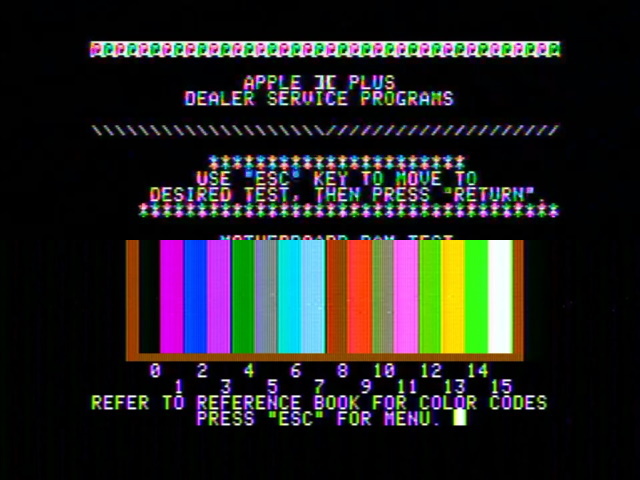
Just for clarity, the issue is only through composite video when combining the Y / C signals to make composite where the issue (caused by the luma signal) can be seen clearly in this image. The change between pixels in the luma signal is being interpreted by the TV as color and needs to be filtered. 

I am generating the signals separately, but due to the resource intensiveness of filters in the FPGA, I want to notch out any frequency in near the 3.579 Mhz region of the luma signal. The current design works to get ride of 90% of the problem but attenuating the filter to get that extra 10% is causing me a lot of issues. Largely the following:

  • If using a shunt filter, when i combine the two signals, I start to filter out the chroma signal as well which kills the color signals because it modulates color at 3.579 Mhz.
  • If I try developing a second order notch filter starting with a shunt filter through a series filter, I can attenuate the signal a bit better but it causes a delay between the luma and chroma signals and I get ghosting on the screen.
  • I'm not sure how to model 2 sources in LTspice to help me with the development process.
    Oddly enough, in my circuit, keeping a 6.8uH inductor (5% tol), I get no major changes in how much rainbowing I can address, and Ive found 300pF to be the sweet spot.
  • I can not add resistance to the luma signal because the 75ohm load of the TV just acts as a voltage divider.


I dont know how many passive options I have here but I wanted to see if I could address it with passive LC components, and I've considered adding an active buffer before both signals but I really need to find a proper way to simulate it before I go out and start building a prototype.

I've include a snap shot of my current design, and for a series filter it works well enough where it does not reduce the sharpness too much but the attenuate needs to be stronger ... I think?


Because of the design of the DAC the following are assumed.

  • Input voltage is 3.2V for the luma signal where the input resistance of the filter is 264 ohms. (Output voltage is 720mV, with a 75Ohm Load)
  • Input voltage is 1.8V for the chroma signal where the input resistance of the chroma signal is 126 ohms (Output voltage is 700mV, with a 75Ohm Load)


I've been causing me a lot of headaches to get the last 5-10% =/


Maybe to add a bit more as well here is what the three signals should look like using a standard SMPTE image:

Luma(This can have very large changes depending on the brightness changes pixel to pixel on the screen):


Chroma:


Composite:


« Last Edit: May 23, 2022, 09:08:43 pm by MikeS11 »
 

Offline Benta

  • Super Contributor
  • ***
  • Posts: 5871
  • Country: de
I get you now.
You want to remove the ~3.58 MHz part of the luma to avoid interference.
Commercial S-Video or Y/C outputs already do this, but it's apparently not part of your FPGA design, is that right?

Hmmm.
Best option would be to modify the FPGA.
Second best: there are pretuned ceramic resonator filters for TVs (hopefully still available) that are designed for this and were earlier used in the billions. Murata comes to mind. But will most likely need buffering.
An ideal inductor and cap might look good in simulation, but making them work in practice is a nightmare. Don't go there.

Good luck.
« Last Edit: May 23, 2022, 09:31:30 pm by Benta »
 
The following users thanked this post: MikeS11

Offline MikeS11Topic starter

  • Newbie
  • Posts: 3
  • Country: ca
I get you now.
You want to remove the ~3.58 MHz part of the luma to avoid interference.
Commercial S-Video or Y/C outputs already do this, but it's apparently not part of your FPGA design, is that right?

Hmmm.
Best option would be to modify the FPGA.
Second best: there are pretuned ceramic resonator filters for TVs (hopefully still available) that are designed for this and were earlier used in the billions. Murata comes to mind. But will most likely need buffering.
An ideal inductor and cap might look good in simulation, but making them work in practice is a nightmare. Don't go there.

Good luck.

Designing it into the FPGA would consume a ton of resources and is not really an option for this project and I've got an ideal cap/ind working somewhat... Ill check option 2! (Though Im not sure Ill find anything :(), I'm fine with requiring any type of buffering, Im just banging my head with perfecting an LC solution.

Thanks!
« Last Edit: May 23, 2022, 10:07:06 pm by MikeS11 »
 

Offline Benta

  • Super Contributor
  • ***
  • Posts: 5871
  • Country: de
I've looked around a bit, and the 3.58 MHz traps are off the market. No dice.
From the old data sheets, the ceramic resonator traps offered +20 dB attenuation, which is about as good as it gets.

Third option: why don't you combine the signals in the FPGA and have a third CVBS output? Much easier, and perhaps more customer friendly?

I prophesize: the LC-filter option will bring no good. Try to simulate using off-the-shelf parts and you'll see what I mean...


Offline Benta

  • Super Contributor
  • ***
  • Posts: 5871
  • Country: de
Yes, those are exactly the ones I meant.
 

Offline dmills

  • Super Contributor
  • ***
  • Posts: 2093
  • Country: gb
This is one of those cases where google patents is worth the time, for example US4893176A, or this one which has an excellent list of related things https://patents.google.com/patent/US5663771A/en.

If your FPGA has a reasonable DSP48 workalike available you can probably implement a comb filter fairly cheaply.
One other observation, you probably have WAY more Luma bandwidth then you need which will not be helping, anything over about 5MHz or so is a big ask for a period telly.
 

Offline BrianHG

  • Super Contributor
  • ***
  • Posts: 7733
  • Country: ca
I am generating the signals separately, but due to the resource intensiveness of filters in the FPGA, I want to notch out any frequency in near the 3.579 Mhz region of the luma signal.
If your FPGA is clocking it's DAC at 14.31818Mhz, or better 28.63636Mhz, such a filter would be nothing more than a few additions and subtractions plus 1 multiply to adjust the filter's emphasis.

How much resources possibly can 4-8 sequential adders plus 1 multiply take up?
For your chroma, you would also need a matched delay, just a DFF fifo chain of 4-8 steps.

How many bits is the source data and your output should be around 8 bits to give you smooth rounded edges before a simple external analog 7Mhz LPF.

With 8 bit out, you can also mix the composite inside the FPGA with one final adder.

Now, decoding the NTSC, this is much more computational intensive and there are things you cannot solve when using non-interlaced 240p outputs from sources like that of Apple II, C64, and Atari 8 bit computers.  Many TVs just cant do much except show color fringes around the fine letters and these computers sometimes use hi-res text mode with patterns in the graphics to artificially generate color, so killing that may be counterproductive.
 

Offline Terry Bites

  • Super Contributor
  • ***
  • Posts: 2391
  • Country: gb
  • Recovering Electrical Engineer


Share me

Digg  Facebook  SlashDot  Delicious  Technorati  Twitter  Google  Yahoo
Smf