Author Topic: This is NOT a Peltz sinusoidal oscillator, but...  (Read 2642 times)

0 Members and 1 Guest are viewing this topic.

Offline SacodepatatasTopic starter

  • Regular Contributor
  • *
  • Posts: 203
  • Country: es
Re: This is NOT a Peltz sinusoidal oscillator, but...
« Reply #25 on: September 27, 2026, 01:11:44 am »

Is the link right? What I see is just a listing of projects.
oops, fixed above.

Thanks ☺️
 

Online PCB.Wiz

  • Super Contributor
  • ***
  • Posts: 3358
  • Country: au
Re: This is NOT a Peltz sinusoidal oscillator, but...
« Reply #26 on: September 27, 2026, 01:14:55 am »
.... Then why every circuit is taking the oscillator's output from the filter's input instead of the filter's output, which always, in more or less amount, will be cleaner than the input? What i'm missing?
Yes, in the simplest versions, the IP node will filter the small amount of clipping that output has, in order to regulate the amplitude.
ie that makes the IP node the cleanest node, as it has a first order LPF at high frequencies.
« Last Edit: September 27, 2026, 01:16:44 am by PCB.Wiz »
 

Offline SacodepatatasTopic starter

  • Regular Contributor
  • *
  • Posts: 203
  • Country: es
Re: This is NOT a Peltz sinusoidal oscillator, but...
« Reply #27 on: September 27, 2026, 01:24:14 am »
Yes, I soon realized that only applies when the gain stage is also the limiting stage. If the limiter is outside, then the amplifier is transparent.
 

Online RoGeorge

  • Super Contributor
  • ***
  • Posts: 8486
  • Country: ro
Re: This is NOT a Peltz sinusoidal oscillator, but...
« Reply #28 on: September 27, 2026, 05:34:58 am »
...Then why every circuit is taking the oscillator's output from the filter's input instead of the filter's output, which always, in more or less amount, will be cleaner than the input? What i'm missing?

Usually the signal is collected from the "input" of the Wien network because that is tied at the output of the opamp.  The output of the opamp is low impedance, which will allow it to drive a load without influencing much the Wien network.  If the generated signal is collected from the "output" of the Wien network, that point has a much higher impedance, so any load will directly influence the Wien network and probably make it stop oscillate, or at least perturb it.


When it comes to very low distort Wien osc, most of the implementation are forgetting one thing:  The CMRR of an opamp is not finite (the common mode rejection ratio), only an ideal opamp has infinite CMRR.  What this means is, if you swing both inputs at the same time, you'll get a parasitic output signal, and that will contribute to the final THD (total harmonic distortions).

Notice how in a generic Wien osc, like the one you show in that example schematic, both the opamp's inputs have to swing around GND.  The voltage swing is usually significant, in the range of volts (the common mode swing is 1/3 of the output):


To get rid of that fraction of distortions (caused by the inputs voltage swing of an opamp with finite CMRR), there is a trick to keep the opamp's inputs at GND at all time, by using two inverting opamps instead of one.  This will cost one more opamp, but it will make the CMRR insignificant, and overall the two opamps will make a Wien oscillator with less THD than a version with a single opamp.  Like this:
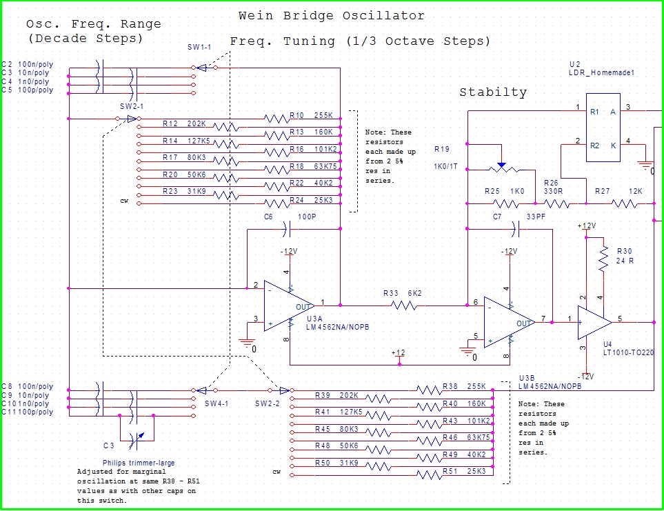

Schematic from https://electroagenda.com/en/low-distortion-audio-oscillator-build/

In this schematic, if you disentangle the Wien oscillator from the rest of frequency range switching, the amplitude control parts and the output power buffer, you are left with a Wien oscillator in which the Wien bridge is distributed over 2 opamps.  This makes possible for both opamps to have their positive input tied to GND, and virtually no common mode swing.  This topology will give lower distortions than a Wien osc with a single opamp.
« Last Edit: September 27, 2026, 05:43:15 am by RoGeorge »
 
The following users thanked this post: Sacodepatatas

Online MariuszD

  • Frequent Contributor
  • **
  • Posts: 694
  • Country: pl
Re: This is NOT a Peltz sinusoidal oscillator, but...
« Reply #29 on: September 27, 2026, 12:10:50 pm »
A similar oscillator can be made with NJFET and PJFET transistors, but the amplitude will be larger.

This schematic can be found under the name lambda diode.
 
The following users thanked this post: RoGeorge, Sacodepatatas

Online MariuszD

  • Frequent Contributor
  • **
  • Posts: 694
  • Country: pl
Re: This is NOT a Peltz sinusoidal oscillator, but...
« Reply #30 on: September 27, 2026, 05:03:03 pm »
The current-voltage characteristic of such a lambda diode depends on the transistors. So the supply voltage needs to be adjusted to match the obtained characteristic. For my simulated diode it looks like that:
2937613-0
Is not suitable for operation with a 5V power supply.

There is a way to do this with a circuit composed of a NJFET and PNP transistor, and a resistor divider. The divider allows modifying the obtained characteristic.
2937617-1
 
The following users thanked this post: RoGeorge, Sacodepatatas

Online MariuszD

  • Frequent Contributor
  • **
  • Posts: 694
  • Country: pl
Re: This is NOT a Peltz sinusoidal oscillator, but...
« Reply #31 on: September 27, 2026, 08:47:57 pm »
I found another circuit very similar in operation to the Peltz oscillator but working with an amplitude equal to the supply voltage. Unfortunately, the amplifier in the CG configuration requires an inductor and a capacitor to separate the DC component, so it will be more difficult to make a version for low frequencies.
 
The following users thanked this post: Sacodepatatas


Share me

Digg  Facebook  SlashDot  Delicious  Technorati  Twitter  Google  Yahoo
Smf


-->