I’m building a CRT-based clock, much like the ones at
http://oscilloclock.com. The 9V wall wart powers both the high voltage board as well as the controller board that generates the waveforms for display. Because the high voltage board generates a fair bit of noise at around 180KHz, I’m using a capacitance multiplier circuit upstream of my 5V linear regulator on the controller board to filter most of the noise. Here's the circuit:
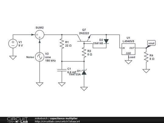
The idea is to choose the value of R1 to create a voltage drop of around 1V, so that there is headroom for the transistor to regulate the output voltage. I breadboarded the circuit, and it works well. I implemented it on my PC board and learned empirically that to get the same 1V voltage drop, I need to reduce the value of R1 from 1K to 470R. I’m driving the same load in each case, and using the same 9V supply as the input in each case.
Although the circuit works acceptably, I’m trying to understand the reason for the difference. I’m using exactly the same components, except that they’re through-hole packages on the breadboard, and surface mount on the PCB. I’ve built up two instances of the PCB, and they behave identically. The breadboard version matches up to the SPICE simulation.
If I look at the 1V drop across the 1K resistor on the breadboard version, it implies a beta of around 100 for the transistor, whereas the 1v drop across 470 ohms on the PCB version implies a beta of about 50. Looking at the data sheet (
https://www.fairchildsemi.com/datasheets/MM/MMBT3904.pdf) for the MMBT3904, I guess both values could be considered in spec with a collector current of around 100mA.
Any ideas?
thx
Mike

 Home
Home Help
Help Search
 Login
Login Register


