Author Topic: best way to measure Q  (Read 5385 times)

0 Members and 1 Guest are viewing this topic.

Offline uer166

  • Frequent Contributor
  • **
  • Posts: 893
  • Country: us
Re: best way to measure Q
« Reply #25 on: January 24, 2020, 01:15:42 am »
Seems like the inductor truly had a terrible Q at those high frequencies (lossy material). I tried another core which is Kool mu with much better results, Q measured at around 108 at 133KHz with ring-down method. De-coupling the function gen even further by adding a 1k resistance in series with it (the one-turn winding) brings Q even further to 160. Adding 10Megs in series with oscilloscope probe doesn't change the result much so I can conclude that its' input impedance doesn't affect it much.

In any case the ring-down method now seems perfect for my measurements (High-Q high-frequency power inductors).
 
The following users thanked this post: ricko_uk

Offline The Electrician

  • Frequent Contributor
  • **
  • Posts: 743
  • Country: us
Re: best way to measure Q
« Reply #26 on: January 25, 2020, 04:32:55 am »
I found a Kool mu core in my core collection (P/N 77439A9) and wound some 14 AWG magnet wire on it.  I ended up with 29 turns.

Using a Hioki impedance analyzer: https://hiokiusa.com/product/impedance-analyzer-im3570/

I measured Q and real part of the impedance over a frequency range of 100 Hz to 1 MHz.  The result of the measurement is shown here.  The Q measurement (green curve) is shown on a linear scale, 100 milliohms at the bottom of the plot and 500 ohms at the top.  The real part of the impedance (yellow) is shown on a log scale with 1 milliohm at the bottom and 50 ohms at the top.

The Q reaches a maximum of 248.9 at about 23 kHz.  The real part begins rising briskly beyond the Q maximum.  Some of the increase in the real part is no doubt due to skin effect losses in the solid magnet wire, and some is due to core loss.

« Last Edit: January 25, 2020, 04:44:05 am by The Electrician »
 
The following users thanked this post: ricko_uk

Offline The Electrician

  • Frequent Contributor
  • **
  • Posts: 743
  • Country: us
Re: best way to measure Q
« Reply #27 on: January 25, 2020, 04:42:00 am »
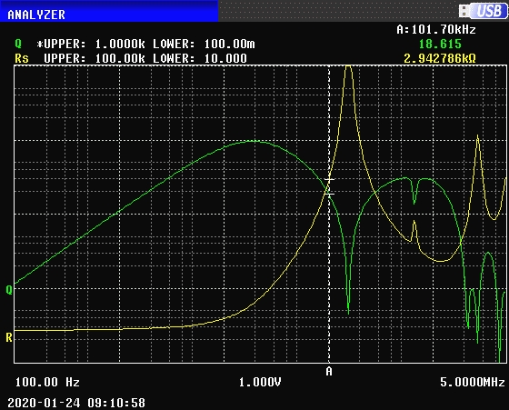
To show the behavior of an inductor above self resonance, here's a another sweep.  This is a commercial 10 mH molded toroidal inductor.  This inductor is rather small and is no doubt wound with many turns of very small magnet wire.

Both plots, Q (green) and Rs (real part, yellow) are shown on a log scale with the upper and lower values of the each plot shown in the upper left part of the image.  The A marker is set to about 100 kHz, and the first self resonance is at about 160 kHz.  The sweep in this plot goes up to 5 MHz and we can see a number of parasitic resonances:
 
The following users thanked this post: ricko_uk


Share me

Digg  Facebook  SlashDot  Delicious  Technorati  Twitter  Google  Yahoo
Smf