Author Topic: Decapping and Chip-Documentation - Howto  (Read 39068 times)

0 Members and 1 Guest are viewing this topic.

Offline NoopyTopic starter

  • Super Contributor
  • ***
  • Posts: 1730
  • Country: de
    • Richis-Lab
Re: Decapping and Chip-Documentation - Howto
« Reply #175 on: December 08, 2022, 03:36:36 pm »
Thanks for trying and sharing the results! :-+

It seems like there are a lot of urban legends around.

Sometime I have to test DMSO again with more temperature...

Offline T3sl4co1l

  • Super Contributor
  • ***
  • Posts: 21658
  • Country: us
  • Expert, Analog Electronics, PCB Layout, EMC
    • Seven Transistor Labs
Re: Decapping and Chip-Documentation - Howto
« Reply #176 on: December 08, 2022, 05:12:02 pm »
Possible the method worked on older resins but not today's. Like the various colored ICs of the 70s, or blob-tops and other somewhat gummy / not-hard transistor bodies.

That doesn't explain how the other guy had success, unless the SOIC(s) were older or just different.  Possible there are still differences today, such as green vs. halogenated resins, etc.

Tim
Seven Transistor Labs, LLC
Electronic design, from concept to prototype.
Bringing a project to life?  Send me a message!
 

Offline NoopyTopic starter

  • Super Contributor
  • ***
  • Posts: 1730
  • Country: de
    • Richis-Lab
Re: Decapping and Chip-Documentation - Howto
« Reply #177 on: January 27, 2023, 08:20:09 pm »


I bought a new tool from Thorlabs. :)
With these pliers you can cut through metal cans (not to big, TO-3 is not possible). A screw makes you stop before you are to deep in the package (a little longer screw would be better).


Nice!  8)
...and I´m a lot faster now.  :-+


https://www.richis-lab.de/Howto_Decap_Metall.htm#Update

 :-/O
 
The following users thanked this post: SeanB, xrunner, Mortymore

Offline magic

  • Super Contributor
  • ***
  • Posts: 6761
  • Country: pl
Re: Decapping and Chip-Documentation - Howto
« Reply #178 on: January 27, 2023, 08:39:15 pm »
LOL, never realized that somebody makes this kind of can openers :D

A screw makes you stop before you are to deep in the package (a little longer screw would be better).
I'm sure it's some off the shelf screw using some standard thread.

If you are lucky it's just M3 or M4, if you are unlucky it some weird-ass "imperial" thing but maybe somebody could ID it if you take outer diameter and thread pitch measurements.
 

Offline NoopyTopic starter

  • Super Contributor
  • ***
  • Posts: 1730
  • Country: de
    • Richis-Lab
Re: Decapping and Chip-Documentation - Howto
« Reply #179 on: January 27, 2023, 08:41:31 pm »
A screw makes you stop before you are to deep in the package (a little longer screw would be better).
I'm sure it's some off the shelf screw using some standard thread.

If you are lucky it's just M3 or M4, if you are unlucky it some weird-ass "imperial" thing but maybe somebody could ID it if you take outer diameter and thread pitch measurements.

Yeah, should be no bigger problem.  :-+ ^-^

Offline NoopyTopic starter

  • Super Contributor
  • ***
  • Posts: 1730
  • Country: de
    • Richis-Lab
Re: Decapping and Chip-Documentation - Howto
« Reply #180 on: January 30, 2023, 07:20:35 pm »


Did I say you can´t cut open bigger packages like TO3?
Haha, you can unscrew the two rollers and screw them into the lower holes! Now you can cut open TO3 packages!  :palm: :-DD :-+


In addition I have added a small advices to the drying agent: I have heard in old devices sometimes barium oxide was used. Barium oxide is poisonous so you better don´t cut transistors open on top of your lunch.


https://www.richis-lab.de/Howto_Decap_Metall.htm

 :-/O
 
The following users thanked this post: Mortymore

Offline NoopyTopic starter

  • Super Contributor
  • ***
  • Posts: 1730
  • Country: de
    • Richis-Lab
Re: Decapping and Chip-Documentation - Howto
« Reply #181 on: April 29, 2023, 06:03:36 am »
For all of you doing "dirty decapping" with heat and are struggling with sticky remainings:

I did some experiments with a fiberglass brush. Sounds rude but did the job quite well.  :-+
It seems that the passivation doesn't get scratched. Bigger metal areas without passivation get scratched but most ICs doesn't have that. I'm talking about metal layers like these:


Next time I will try to remove polyimide (after some mild heat treatment that usually is not enough to decompose it).
 
The following users thanked this post: RoGeorge

Offline RoGeorge

  • Super Contributor
  • ***
  • Posts: 6186
  • Country: ro
Re: Decapping and Chip-Documentation - Howto
« Reply #182 on: July 13, 2023, 05:22:38 am »
Read today about this unusual decapping method that uses high voltage/plasma from a Tesla coil, instead of chemicals.  Linking it here just for the docs:
https://hackaday.com/2023/07/12/no-acid-open-ics-with-a-tesla-coil/
https://hackaday.io/project/191416-integrated-circuit-decapping-without-acid
 
The following users thanked this post: Mortymore, Noopy

Offline NoopyTopic starter

  • Super Contributor
  • ***
  • Posts: 1730
  • Country: de
    • Richis-Lab
Re: Decapping and Chip-Documentation - Howto
« Reply #183 on: January 16, 2024, 04:26:42 am »
I have updated the optical section of my HowTo:


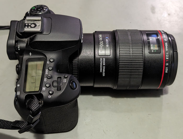
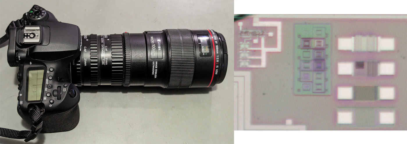
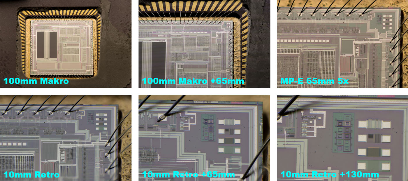
First of all the Canon 90D with the Canon EF 100mm f/2,8L Macro. That´s a surprising performance for a "normal" Macro objective. You can identify the 10µm lines!  :-+

The Canon 90D has an APS-C sensor and therefore multiplies by a factor of 1,6. A magnification factor of 1,6 seems very small, but you have to take the high resolution of the digital camera into account. The Canon 90D offers a resolution of 32,5 megapixels. If you are satisfied with 2 megapixels, you already achieve a magnification factor of 26:1. A high pixel density is therefore an advantage here.


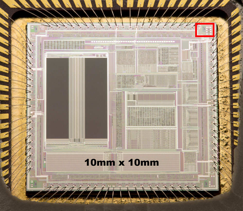
We will take a closer look at this area...


Taking pictures of these small things don´t close the aperture. You need magnification and resolution capacity. Closing the aperture reduces the resolution capacity and your magnification gets useless.


Distance rings can increase the magnification but the pictures is just a little better. With more distance it gets worse.


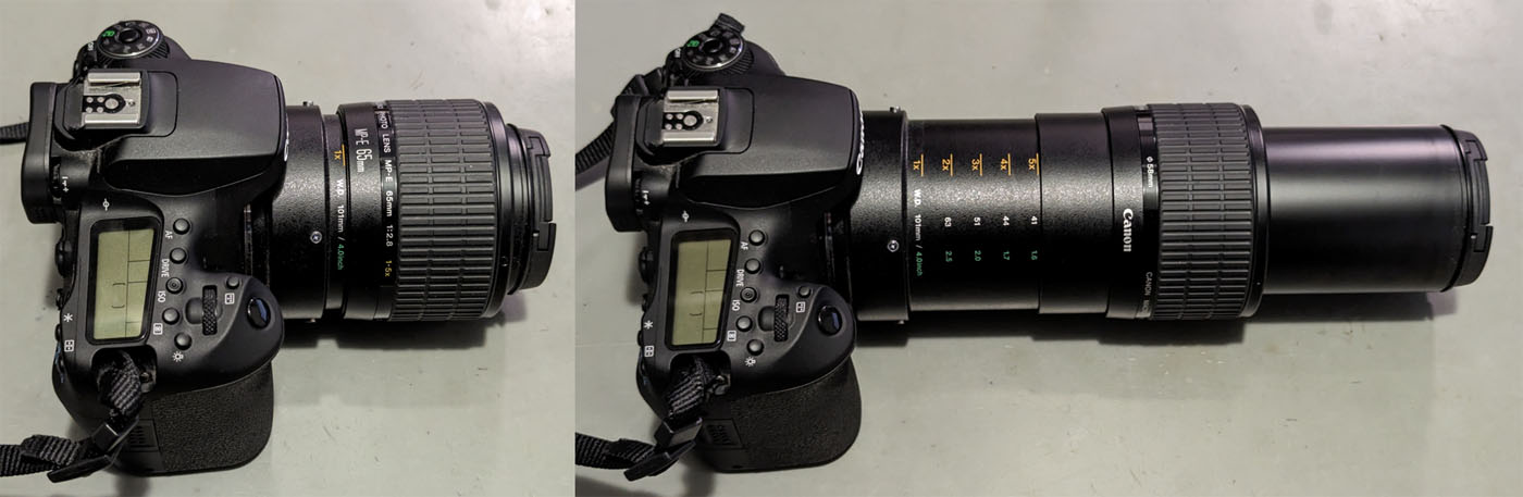
The Canon MP-E 65mm f/2,8 1-5x macro is a magnifying lens that provides image scales between 1:1 and 5:1. On the Canon 90D, this corresponds to an image scale of up to 8:1. If you are satisfied with a 2 megapixel section, this is a magnification factor of 130:1.

One disadvantage of the magnifying lens is the lack of a focus setting. You therefore have to move the camera or the object to focus the image. This is not an easy task with such high magnification factors.


Compared to the Canon EF 100mm f/2,8L Macro, the image quality of the magnifying lens is significantly better.


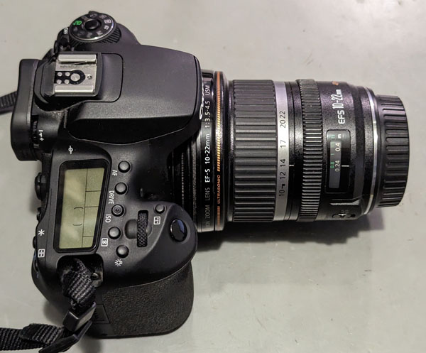
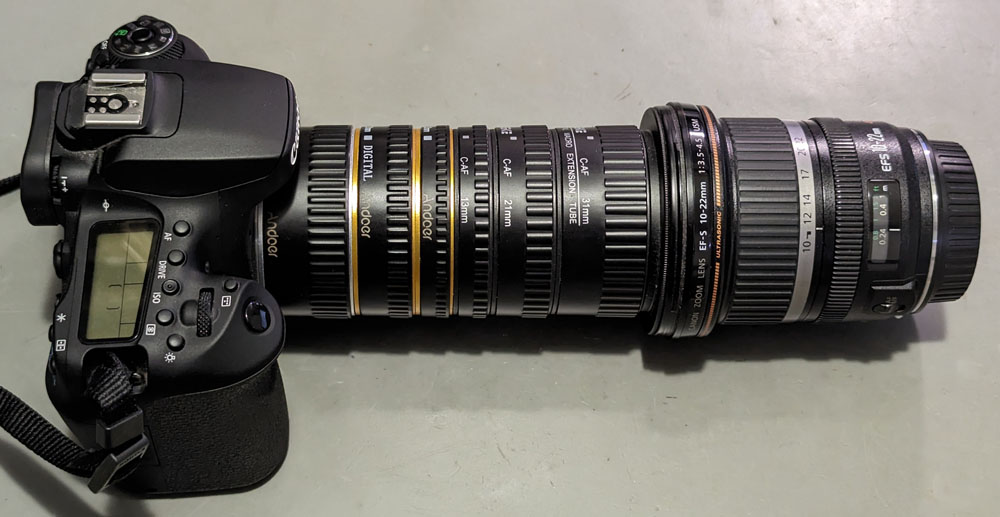
Another option for achieving high magnification factors is the use of so-called retro adapters. This allows the lens to be attached to the camera with the lens normally on the outside. The adapters required for this are available for various camera types and filter threads. The camera can then no longer adjust the aperture and focussing. However, the aperture setting is not usually required and focussing is done manually anyway.

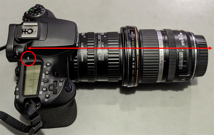
Not every lens is suitable for this application. A small focal length produces a high magnification factor in this configuration. The best results were achieved with the Canon EF-S 10-22mm f/3,5-4,5 shown here. The Canon EF-S 18-135mm f/3,5-5,6 kit lens is also well suited, but this only has a sluggish micromotor focus adjustment, not an ultrasonic motor. The otherwise almost flawless Canon EF 24-70mm f/2,8L produces surprisingly poor images. Looking at the specifications, the Canon EF 28MM f/1,8 USM also seems very suitable. It has a small focal length for a large magnification factor, it has a large aperture, which promises a high resolving power and ultrasonic focussing. In fact, this lens also delivers noticeably poorer results than the Canon EF-S 10-22mm f/3,5-4,5.


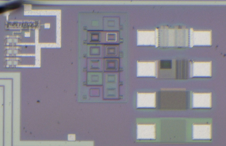
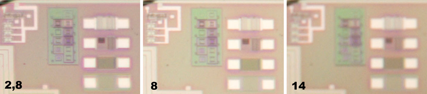
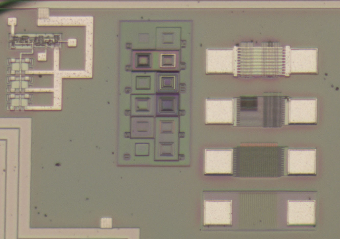
This image shows just how important a small focal length is. The 1:1 image section was taken at the 22mm setting of the Canon EF-S 10-22mm f/3,5-4,5. The limiting factor here is the resolution, but the magnification factor does not offer any major reserves too.


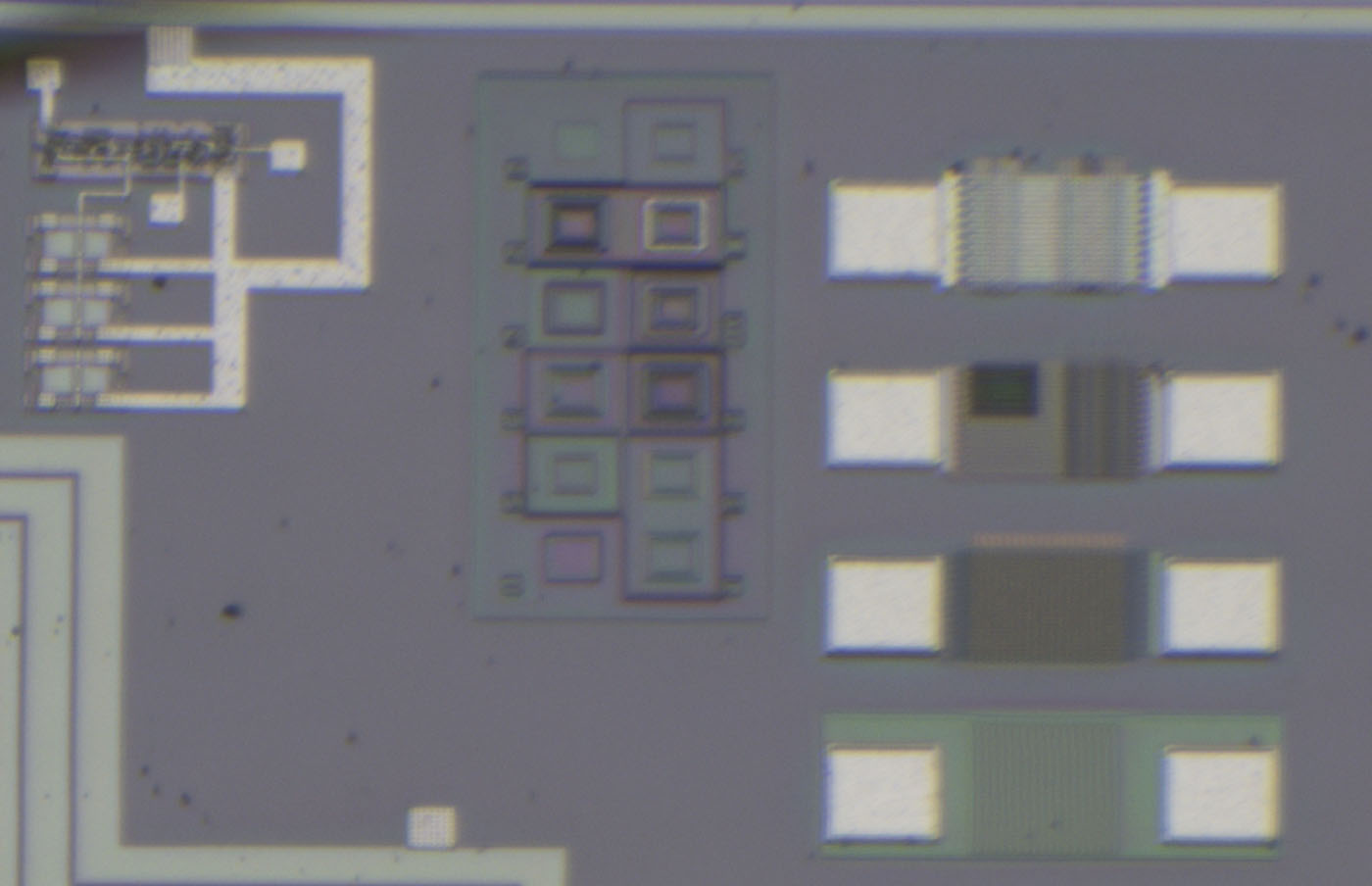
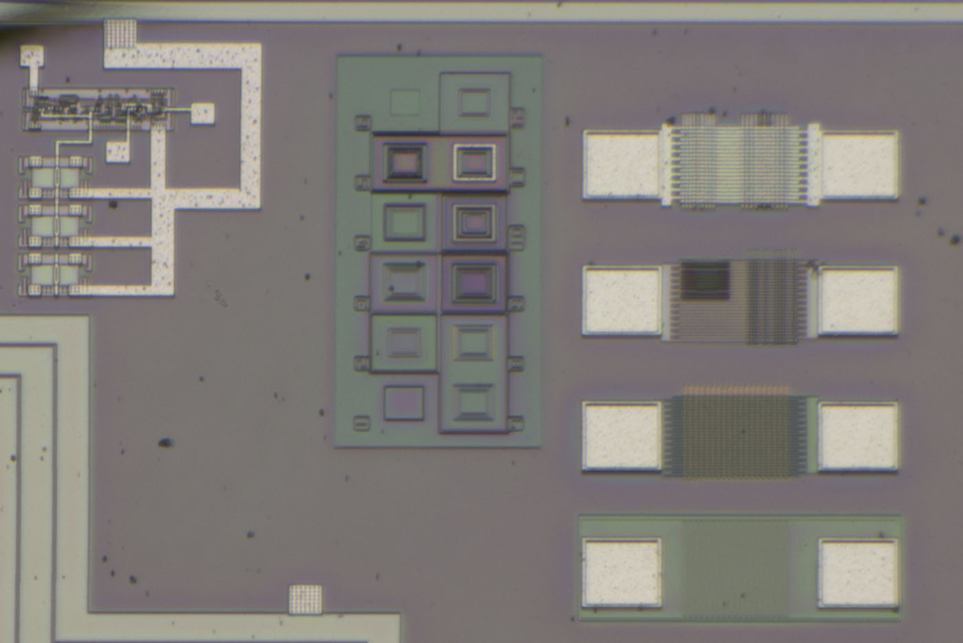
With the 10mm setting, I already had to reduce the image size slightly. At first glance, you might think that the image has deteriorated somewhat, but in fact the opposite is the case. In the top left-hand corner there is a test structure with smaller and larger elements. In the case of the larger elements, you can already see the contacts to the metal layer. Up to this point, however, the magnifying lens still offers better results.


If the retro system is supplemented with distance rings, the magnification factor increases. The images above already show that the resolution is the limiting factor. At the same time, the spacer rings reduce the amount of light reaching the sensor. However, this measure still has a positive effect on the image quality. This can be explained by the fact that lenses are optimised for certain minimum distances. With the Canon EF-S 10-22mm f/3,5-4,5, the close-up limit is 24cm. This is the minimum distance that must be maintained between the object and the camera sensor. Most cameras have a symbol on them that indicates the exact location at which the sensor is located. The distance between the object and the lens is only a few centimetres. With the distance rings, the total length of the optical path is approximately in the range of the close-up limit.


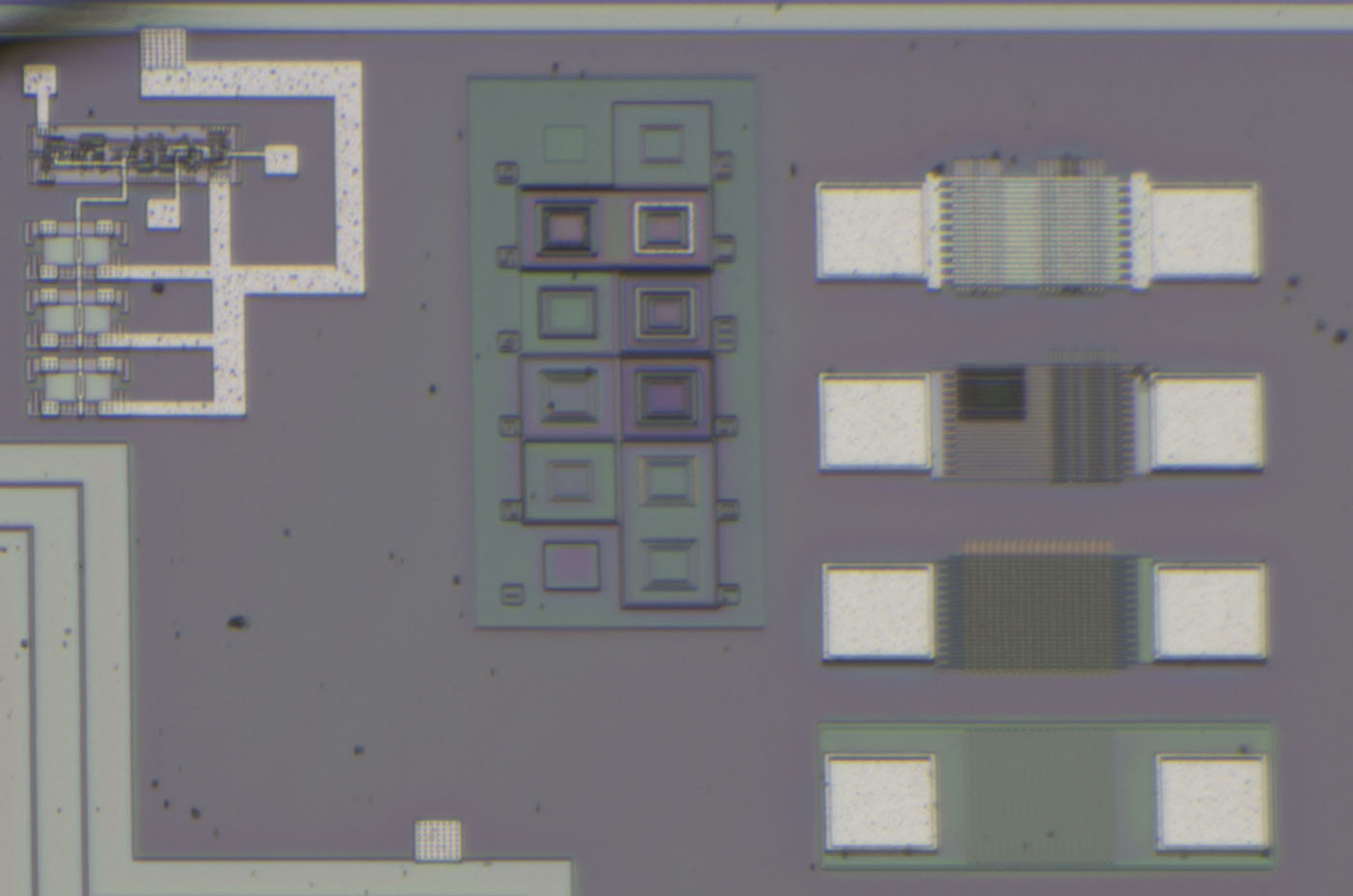
The image quality is significantly better with the 65mm distance rings.


With a second set of spacer rings between camera and lens, the distance increases to 130mm and the image quality improves slightly. The magnification factor increases further.

A third set of spacer rings, which increases the distance to 195mm, does not improve the image quality any further.


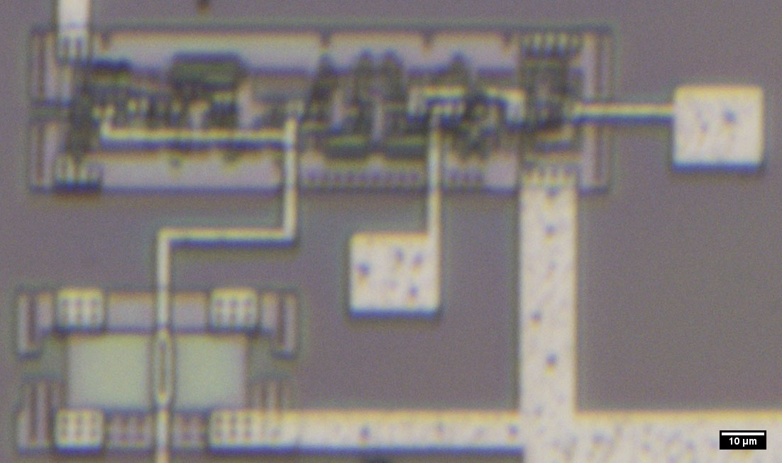
With the Canon EF-S 10-22mm f/3,5-4,5 and 130mm distance rings, one millimetre is imaged with 6.030 pixels. This means that there are six pixels in the distance of one micrometre. The sensor of the Canon 90D is 22,3mm wide and resolves this width with 6.960 pixels. That is 312 pixels per millimetre. This results in a magnification factor of 19,3:1. In relation to a 2 megapixel image section, the factor is 314:1. Here you can see a 1:1 image section. Depending on which structures are involved, elements as small as 1 µm can be recognised.


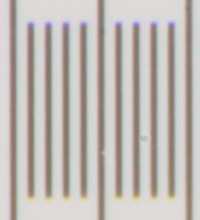
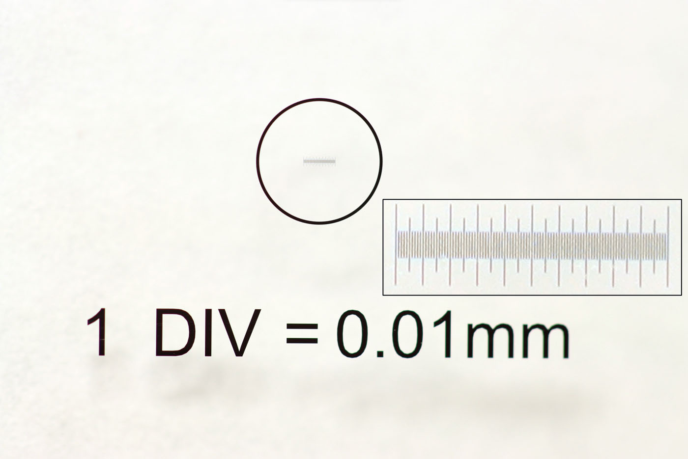
This 1:1 image section shows the lines on the scale with their distance of 10µm.


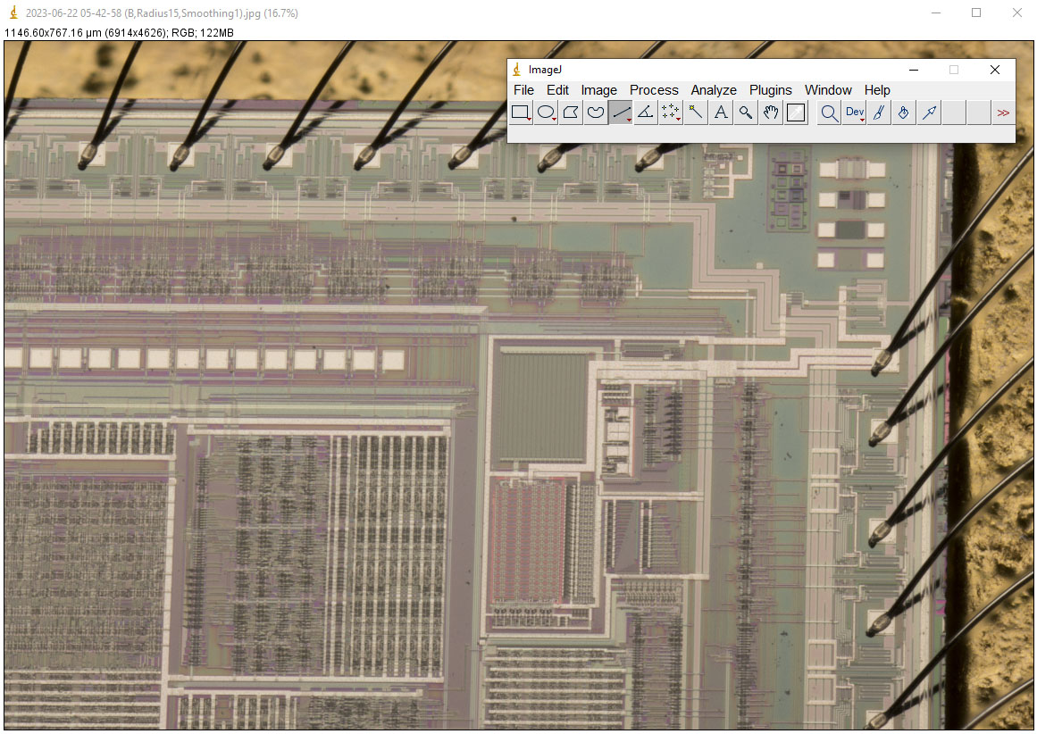
If you know the magnification factor of the structure, you can carry out measurements in the images. The freeware ImageJ is very well suited for this.

If the image is focussed with the focus ring of the lens, the magnification factor also changes. The focus setting is not saved, resulting in an additional measurement error when calculating the actual size from the number of pixels. In the case of the Canon EF-S 10-22mm f/3.5-4.5, however, the additional measurement error is a reasonable 1%.


Here you can see the image sections that result from the different configurations. A large magnification factor is desirable in order to make small details visible. At the same time, however, the image section becomes smaller and smaller. You then have to either create panoramic images or take individual detailed images with the appropriate magnification factors.

The high resolution of digital cameras is a great advantage here, as a tolerably large image section remains available even with large magnification factors.


 ;D

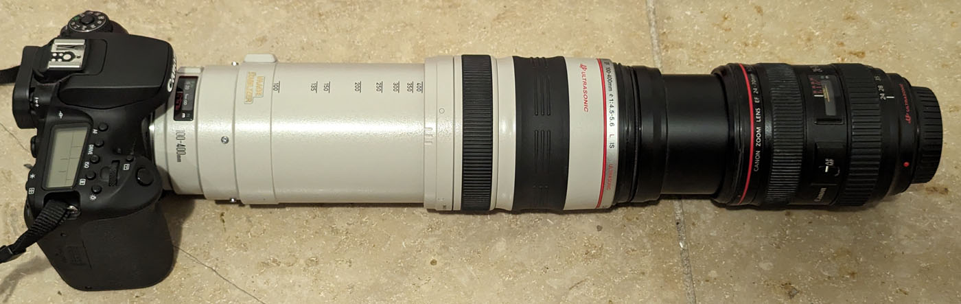
Instead of the spacer rings, you can install a lens in a normal configuration between the camera and the retro lens. This requires an adapter with two matching filter threads. The additional lens adapts the light path of the retro lens to the camera. The magnification factor then corresponds to the ratio of the focal lengths. Here, the Canon EF 100-400mm f/4,5-5,6L IS USM with the Canon EF 24-70mm f/2,8L produces a magnification factor of 16,6:1, in relation to 2 megapixels this would be a magnification factor of 271:1.

Configurations with different lenses were tested. No combination delivers good image quality. The resolution is poorer, especially in the peripheral areas and chromatic aberration is clearly visible.


https://www.richis-lab.de/Howto_Optik.htm

 :-/O
« Last Edit: January 16, 2024, 04:35:23 am by Noopy »
 
The following users thanked this post: SeanB, RoGeorge, BILLPOD

Offline magic

  • Super Contributor
  • ***
  • Posts: 6761
  • Country: pl
Re: Decapping and Chip-Documentation - Howto
« Reply #184 on: January 16, 2024, 11:54:52 pm »
What about your microscope images, though? You can't hide it from me ;)


Taking pictures of these small things don´t close the aperture. You need magnification and resolution capacity. Closing the aperture reduces the resolution capacity and your magnification gets useless.
Actually, your f/2.8 sample is not much sharper than f/8, so it's limited by aberrations rather than diffraction.
It is possible that stopping down slightly (maybe f/3.5 or f/4) would bring small improvement. This appears to be common in photographic lenses.

If the retro system is supplemented with distance rings, the magnification factor increases. The images above already show that the resolution is the limiting factor. At the same time, the spacer rings reduce the amount of light reaching the sensor. However, this measure still has a positive effect on the image quality. This can be explained by the fact that lenses are optimised for certain minimum distances. With the Canon EF-S 10-22mm f/3,5-4,5, the close-up limit is 24cm. This is the minimum distance that must be maintained between the object and the camera sensor.
It may be possible to reduce minimum focus distance with a closeup lens in order to reduce magnification and gain field of view. 6 pixels per micron is overkill.
 

Offline NoopyTopic starter

  • Super Contributor
  • ***
  • Posts: 1730
  • Country: de
    • Richis-Lab
Re: Decapping and Chip-Documentation - Howto
« Reply #185 on: January 17, 2024, 04:03:34 am »
What about your microscope images, though? You can't hide it from me ;)

 ;D You are right. Unfortunately ther is not much to show. I got a few pictures from other people, I payed for a few pictures and somtimes I can put my hands on a real microscope.

But I should add an comment that not every picture is taken with the DSLR. I don´t want to make poeple sad trying the DSLR way.


Taking pictures of these small things don´t close the aperture. You need magnification and resolution capacity. Closing the aperture reduces the resolution capacity and your magnification gets useless.
Actually, your f/2.8 sample is not much sharper than f/8, so it's limited by aberrations rather than diffraction.
It is possible that stopping down slightly (maybe f/3.5 or f/4) would bring small improvement. This appears to be common in photographic lenses.

I agree with you, the sharpness is very similar but the f/8 is a little worse I would say. I once tried smaller steps but didn´t find a configuration that show better quality pictures. The real increase in quality comes with the distance between camera and lens.


If the retro system is supplemented with distance rings, the magnification factor increases. The images above already show that the resolution is the limiting factor. At the same time, the spacer rings reduce the amount of light reaching the sensor. However, this measure still has a positive effect on the image quality. This can be explained by the fact that lenses are optimised for certain minimum distances. With the Canon EF-S 10-22mm f/3,5-4,5, the close-up limit is 24cm. This is the minimum distance that must be maintained between the object and the camera sensor.
It may be possible to reduce minimum focus distance with a closeup lens in order to reduce magnification and gain field of view. 6 pixels per micron is overkill.

Here I agree with you too. But I once tried a closeup lens and wasn´t happy with the pictures. Perhaps the quality of the lens wasn´t good enough.  :-//
6 pixels per micron is more than we need but not way to much. As I said sometimes I can recognise 1µm structures. (Unfortunately I have no µm scale to double check.)
« Last Edit: January 17, 2024, 05:03:28 am by Noopy »
 

Offline NoopyTopic starter

  • Super Contributor
  • ***
  • Posts: 1730
  • Country: de
    • Richis-Lab
Re: Decapping and Chip-Documentation - Howto
« Reply #186 on: January 20, 2024, 04:25:07 am »
An update to the light topic. For a lot of you guys there is not much new information but it was necessary to tune some things and add some pictures.


With very high magnification factors, the mechanical structure of the optical system must be as stable as possible. The slightest movements or even vibrations can lead to blurred images. There are tripods that fix the camera with its lens vertically. The object is then positioned underneath. These tripods are also available motorised so that they can be used for focusing. An alternative is to align the optical axis horizontally. In this case, the camera rests on an ESD mat, the surface of which provides a certain degree of adhesion and at the same time absorbs vibrations.

The camera is triggered with a remote control so that the camera is not moved. Mirrorless cameras are an advantage at this point. The movement of the mirror already generates enough vibrations that the image quality sometimes deteriorates. With SLR cameras, you can use the mirror lock-up function. The camera first moves the mirror and exposes the sensor only after a short pause. The Canon 90D offers a particularly advantageous function in this respect. The electronic shutter makes it possible to take pictures without activating the mechanical shutter, so that nothing moves in the camera at all.

At high magnification factors, the area that is displayed in focus is very narrow. The system must be focussed accordingly. Once you have roughly positioned the object to be imaged, focussing is finally carried out using the focus ring. An ultrasonic focussing system is advantageous here, as its focus ring is very smooth-running. The image quality is monitored via the camera's monitor, which is usually sufficient. However, the camera could of course also be connected to an external monitor.

The object is fixed and positioned using a classic third hand and a more modern version of this aid. A micropositioning system would enable easier and more precise positioning, but is less flexible.The third hand allows the object to be tilted quickly. It can also be used to quickly switch from individual dies to larger packages. At high magnification factors, it is extremely important to keep the arm for aligning the object as short as possible. The length seen in the image on the right increases the effect of small vibrations.

As you can see here, the distance between the lens and the object is relatively large. This makes it easier to document elements with taller structures in the immediate vicinity.


One crocodile clip of the third hand is used for larger elements. The other crocodile clip is wrapped with double-sided adhesive tape. This makes it easy to attach and detach the elements.The third hand is very stable, but can still be moved easily if the picture section is not the right one.


If you want to create panoramic images, you need an XY micromanipulator. This is the only way to take series of images of sufficient quality for larger panoramas. The micromanipulator shown here is very slim, which makes it easier to bring in light from behind the object. There is a round surface on the front which is covered with double-sided adhesive tape. In addition to X and Y displacement, the micromanipulator also allows swivelling around the X and Y axes. Panning is very important in order to bring the object completely into the focal plane.

The coarse alignment in the X and Z directions can be achieved by moving the micromanipulator. A small holder was constructed for the coarse alignment in the Y direction. Two grub screws attach a metal block to a threaded rod. The micromanipulator has a union nut at the rear end with which it is screwed to the metal block.


Different light sources and lighting angles create very different optical effects. This can be used to emphasise certain structures.


The surface of integrated circuits appears black. The metal layer consists of aluminium or copper and shows the typical colours of a metal surface. The silicon oxide layer on top, which protects the integrated circuit, is transparent. It is almost impossible to recognise details with such an image. Apart from the metal layer, only a few edges are faintly visible. The edges are the result of unevenness that occurs when the individual elements of the integrated circuit are integrated.

If coaxial lighting is used, the various elements integrated in the silicon are clearly visible. For an analysis, it is important to understand that the areas do not actually bear these colours. The colours are caused by resonances in the thin silicon oxide layer on the surface of the integrated circuit. When building up the different areas, the silicon oxide layer is repeatedly opened locally and then a new layer is applied over the entire surface. This results in silicon oxide layers of different thicknesses on the various areas. Destructive and constructive interferences occur for some wavelengths and different colours can be observed accordingly.

When interpreting the colours, you must always bear in mind that these are not real colours, but light resonances.
This means that different colours can occur for the same component with different types of illumination. As the colours depend on the thickness of the silicon oxide layer, it can happen that different areas show the same colours. Bevels also form at the edges between two areas, which can show different colours even though there is no third area in between.

In principle, any light source can be used. However, a fluorescent tube produced the most colours, which is very helpful when analysing circuits.


Microscopes that offer coaxial light couple the light for illuminating of the object with a semi-transparent mirror into the optical axis of the objective. This is difficult to realise with the setup described here. However, it has been shown that a similar effect occurs when the light source is placed behind the object.

If the light source is fixed directly behind the object, the image quality deteriorates. Placing it a little way off the optical axis proves to be optimal. The die is positioned vertically on the optical axis of the lens. It appears that some of the light is reflected by the lens and then acts like coaxial light.


Interestingly, the same effect occurs if you position the die at an angle and shine the light on the object from a similar angle. Due to the tilted position, focus stacking is absolutely necessary here.


It can be seen that the tilted images (right) reveal a little more details.


The images taken at an angle have another advantage. They show the surface structure of the IC. However, you have to be careful when interpreting the structures. The image on the left was taken at an angle and with illumination behind the IC. Even if it looks partially different in this example, the image quality is usually somewhat poorer in this configuration. However, the surface structure can be seen as it actually is on the chip. The transistors are located in recesses.

The above arrangement usually results in the centre image. At first glance, the surface structure appears inverted. The transistors now appear to be located on sockets. How this effect arises is unclear. If you want to understand and interpret the surface structure, it helps to assume that the light source is located below the image. In this way, the shadows correspond to the actual geometries. This becomes clearer if you rotate the image by 180° (right). Here the transistors appear to be located in recesses, as is the case in reality.


If you are documenting higher and more complex structures, good light distribution is very important. The fluorescent tube with its reflector is significantly larger than the objects to be depicted, but it still produces disturbing reflections and shadows. A folded sheet of paper is a simple remedy. It reduces the light intensity more than a diffuser, which is designed for this purpose. However, this is not a major disadvantage here because the exposure time is not critical.


https://www.richis-lab.de/Howto_Licht.htm

 :-/O
 
The following users thanked this post: RoGeorge, ArsenioDev

Offline DavidAlfa

  • Super Contributor
  • ***
  • Posts: 5896
  • Country: es
Hantek DSO2x1x            Drive        FAQ          DON'T BUY HANTEK! (Aka HALF-MADE)
Stm32 Soldering FW      Forum      Github      Donate
 

Offline NoopyTopic starter

  • Super Contributor
  • ***
  • Posts: 1730
  • Country: de
    • Richis-Lab
Re: Decapping and Chip-Documentation - Howto
« Reply #188 on: January 20, 2024, 05:52:22 am »
As soon as I get one of these I promise to take some pictures.  ;D

Offline magic

  • Super Contributor
  • ***
  • Posts: 6761
  • Country: pl
Re: Decapping and Chip-Documentation - Howto
« Reply #189 on: January 20, 2024, 11:41:48 am »
Once you have roughly positioned the object to be imaged, focussing is finally carried out using the focus ring.
This wouldn't work with lots of mirrorless system lenses as they focus by means of motors moving lens groups inside.
Even manual focusing requires power (and perhaps data connection with the camera too).

Microscopes that offer coaxial light couple the light for illuminating of the object with a semi-transparent mirror into the optical axis of the objective. This is difficult to realise with the setup described here.
Well, you could drill a large hole in the side of an extension tube and put a thin glass plate inside at 45°. That's what I do, but with smaller lenses and smaller sensors. (Forget smartphone mirror foil, it's crap. I use microscope slide or cover glasses now.)

Or put a glass between the reversed lens and the die, plenty of space for that with SLR lenses thanks to long flange focal distance. This introduces some astigmatism if lens aperture is too wide and IMO sharpness is barely passable near f/4 even with 0.17mm glass, but it's very easy to experiment with.

With these techniques the chip can be 90° to the camera to avoid focus stacking, but light may still be angled to produce some shadows.

The above arrangement usually results in the centre image. At first glance, the surface structure appears inverted. The transistors now appear to be located on sockets. How this effect arises is unclear. If you want to understand and interpret the surface structure, it helps to assume that the light source is located below the image. In this way, the shadows correspond to the actual geometries. This becomes clearer if you rotate the image by 180° (right). Here the transistors appear to be located in recesses, as is the case in reality.
Did you try simply moving the lamp further away from the camera, above the chip?
If you have problems with flare, make a suitable lens hood from black paper.
« Last Edit: January 20, 2024, 12:07:53 pm by magic »
 

Offline NoopyTopic starter

  • Super Contributor
  • ***
  • Posts: 1730
  • Country: de
    • Richis-Lab
Re: Decapping and Chip-Documentation - Howto
« Reply #190 on: January 20, 2024, 12:50:59 pm »
Once you have roughly positioned the object to be imaged, focussing is finally carried out using the focus ring.
This wouldn't work with lots of mirrorless system lenses as they focus by means of motors moving lens groups inside.
Even manual focusing requires power (and perhaps data connection with the camera too).

You need a "big" mirrorless camer like the EOS R.  8)
These system cameras are probably not the right tool.


Microscopes that offer coaxial light couple the light for illuminating of the object with a semi-transparent mirror into the optical axis of the objective. This is difficult to realise with the setup described here.
Well, you could drill a large hole in the side of an extension tube and put a thin glass plate inside at 45°. That's what I do, but with smaller lenses and smaller sensors. (Forget smartphone mirror foil, it's crap. I use microscope slide or cover glasses now.)

Or put a glass between the reversed lens and the die, plenty of space for that with SLR lenses thanks to long flange focal distance. This introduces some astigmatism if lens aperture is too wide and IMO sharpness is barely passable near f/4 even with 0.17mm glass, but it's very easy to experiment with.

With these techniques the chip can be 90° to the camera to avoid focus stacking, but light may still be angled to produce some shadows.

I once tried a semi transparent mirror between the lens and the die. The image quality deteriorated badly. Perhaps the problem was the thickness of the mirror. Well it was the one thing I was able to put my hands on...

Would just thin glass do the job?


The above arrangement usually results in the centre image. At first glance, the surface structure appears inverted. The transistors now appear to be located on sockets. How this effect arises is unclear. If you want to understand and interpret the surface structure, it helps to assume that the light source is located below the image. In this way, the shadows correspond to the actual geometries. This becomes clearer if you rotate the image by 180° (right). Here the transistors appear to be located in recesses, as is the case in reality.
Did you try simply moving the lamp further away from the camera, above the chip?
If you have problems with flare, make a suitable lens hood from black paper.

If you move the lamp further away but remain the angle it doesn´t change anything. You just have less light.
If you move the lamp away from the camera changing the angle then at first you get "normal" black&white pictures and then you get pictures like the left of the three I showed here.

Flare is not really a problem as long as you don´t put the light directly in the optical path of the lens.  :-+

Offline magic

  • Super Contributor
  • ***
  • Posts: 6761
  • Country: pl
Re: Decapping and Chip-Documentation - Howto
« Reply #191 on: January 20, 2024, 05:19:07 pm »
Sorry, I remembered wrong - the astigmatism really sucks. I tried it on OP07 with a 5x microscope objective (same chip and same objective as here). I believe it has about similar aperture as f/4 photographic lens in reverse so the results may be similar too. Test images attached: one focused on horizontal lines, one on vertical lines, one in the middle, one with the mirror behind the lens (between the lens and the camera). Differences are quite obvious. Ignore bad white balance.

Astigmatism dramatically increases with aperture (10x objective results were no better than 5x, maybe worse) and equally dramatically decreases when stopping down. Effective aperture (on the camera side) of basic microscope objectives is ~f/20 and I can't see any difference with a 1mm glass plate being there or not. Placing the glass in front may work well at lower magnifications, where wide (object-space) aperture is not so critical for resolution. I remember reading that some coin photographer was happy with it.

Yes, ordinary glass works well, but it needs to be high quality and flat to avoid spots of blur and distortion. I found that "$1 for a pack of 100" cover glasses (24x24x0.17mm) are not satisfactory, and this is visible right away - if I look through such glass and move it a little, the scene behind shifts and distorts. Professional glasses from reputable manufacturers should be better. OTOH, my "$2 for a pack of 50" slide glasses (75x25x1mm) are perfect, YMMV. The coin photographer used photographic UV filters - these should be good too, but I don't know their thickness.

A glass plate at 45° angle passes about 80% of light and reflects 20% sideways (10% from each air to glass surface, these two reflections are offset from one another by the thickness of glass but it's not a big deal in lighting). A potentially bigger issue is ghost image - 10% of passing light reflects internally instead of exiting the glass, and 10% of it reflects again and exists in parallel with the original light. However, 1% of the original image is over 6 stops darker and rarely visible. Did anyone notice ghost image on my LM4562? See below with contrast tweaked for maximum visibility.
« Last Edit: January 20, 2024, 05:22:40 pm by magic »
 
The following users thanked this post: RoGeorge

Offline NoopyTopic starter

  • Super Contributor
  • ***
  • Posts: 1730
  • Country: de
    • Richis-Lab
Re: Decapping and Chip-Documentation - Howto
« Reply #192 on: January 20, 2024, 07:44:19 pm »
With the glass between the camera and the lens the picture looks very good.  :-+

My problem is that I want a mechanical robust solution which is still good to handle. I should start working with 3D printers...


Share me

Digg  Facebook  SlashDot  Delicious  Technorati  Twitter  Google  Yahoo
Smf