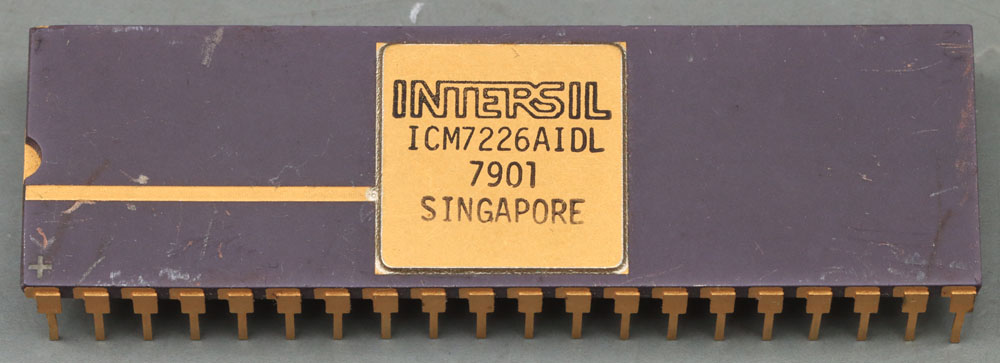
The Intersil ICM7226A is a fully integrated frequency counter that can determine frequencies up to 10MHz. The component with index A is designed to drive 7-segment displays with a common cathode. The ICM7226B, on the other hand, drives 7-segment displays with a common anode.
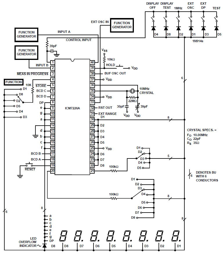
The test circuit in the datasheet shows how efficiently the ICM7226 is constructed. The module contains an oscillator and directly drives eight 7-segment displays. The outputs, which multiplex the individual digits, are used simultaneously to read in the function selection and the counting range.
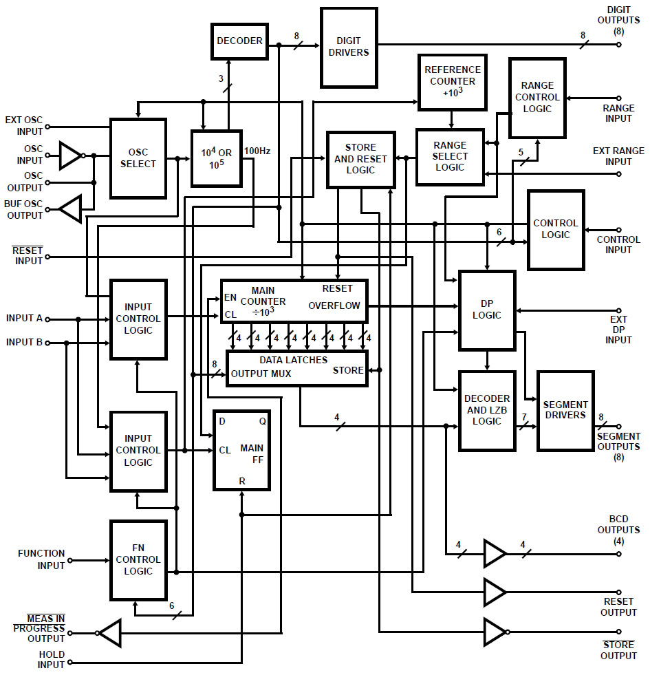
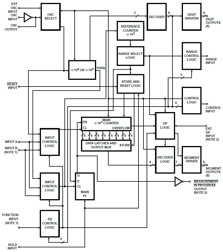
The ICM7226 datasheet contains a detailed block diagram showing how the chip does the counting.
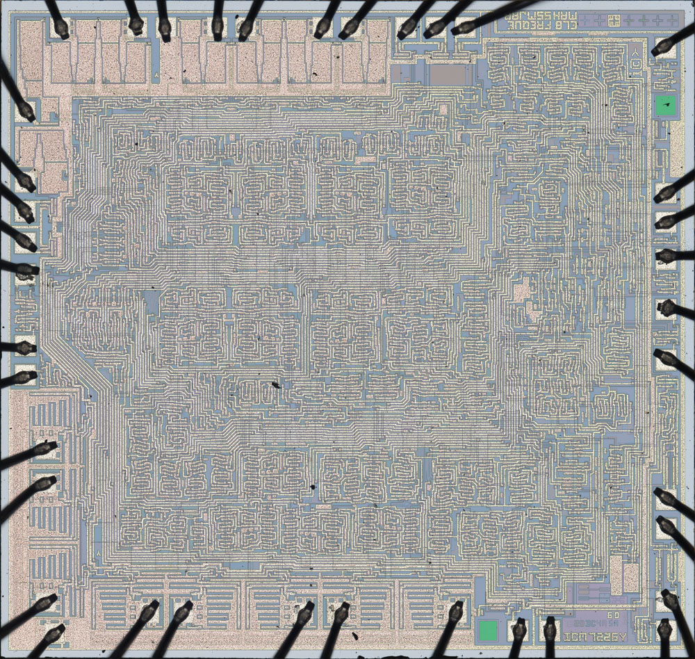
The dimensions of the die are 4,3mm x 4,1mm. The image is available in original size:
https://www.richis-lab.de/images/counter/01x03XL.jpg (29MB) It can be seen that the design would provide two additional bondpads. However, these bondpads are not metallised, so they can only be used when a different metal layer is used.
The lowside transistors, which control the segments of the active 7-segment display, are located at the top edge. The highside transistors, each of which activates one of the 7-segment displays, are located in the bottom left-hand corner. Repeating structures can be recognised in the core of the ICM7226. The majority of these areas are likely to contain frequency dividers, of which a large number is required.
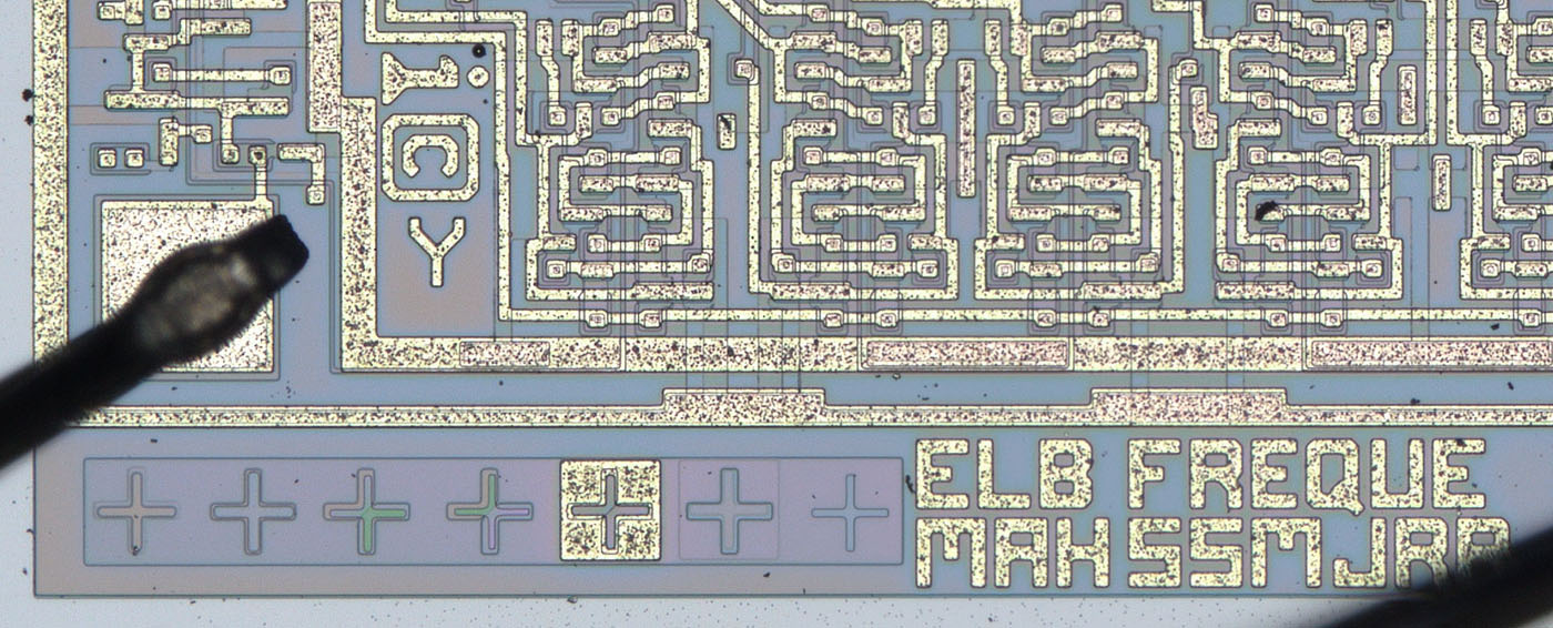
Test structures are integrated in the top right-hand corner. Next to them are character strings that could be the initials of the developers, among other things.
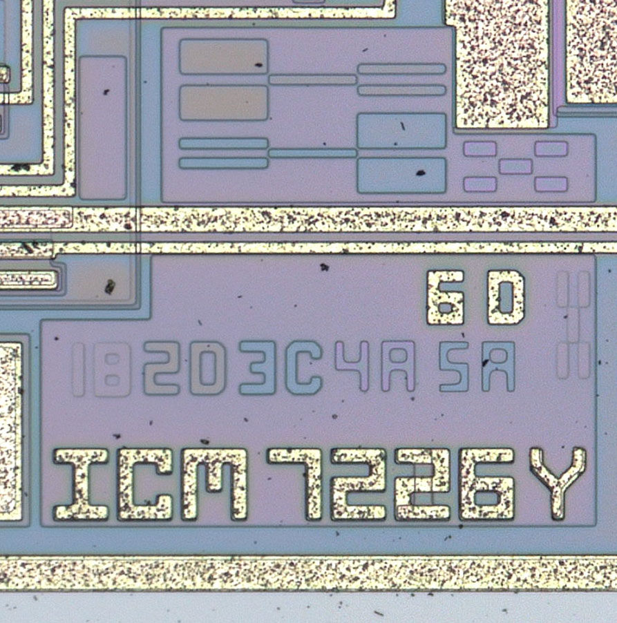
The revisions of six masks can be seen in the bottom right-hand corner. The designation ICM7226 is shown underneath. Y appears to be the revision of the design. The Y appears several times on the die. If we assume that we are counting backwards from Z, then this is a second revision.
A closer look reveals that a 1 is depicted in a lower position in place of the second 2. This indicates that the design could be used for both the ICM7226 and the ICM7216. All you have to do is change the metal layer.
The ICM7216 offers slightly fewer interfaces due to its smaller housing, in particular the BCD output is missing. Otherwise it is the same module. It therefore makes sense to operate the ICM7216 and the ICM7226 with the same circuit.
https://www.richis-lab.de/counter01.htm 


