Author Topic: Different die pictures  (Read 86289 times)

0 Members and 1 Guest are viewing this topic.

Offline NoopyTopic starter

  • Super Contributor
  • ***
  • Posts: 1734
  • Country: de
    • Richis-Lab
Re: Different die pictures
« Reply #50 on: November 23, 2020, 10:35:02 pm »
How are those clamping diodes supposed to work? They look like normal transistors with open circuit bases.

I assume that´s a standard transistor and the "T" connects the base (vertical) with the collector (horizontal). That would leave a base-emitter-junction which gives us a zener Diode with some volts.
Of course I´m not 100% sure about that but that´s the only function that makes sense. It´s a component connected only between the output and ground. It´s too big to be a surge suppressor but you definitly need a clamping circuit in such a lowside switch.

Online mawyatt

  • Super Contributor
  • ***
  • Posts: 3263
  • Country: us
Re: Different die pictures
« Reply #51 on: November 25, 2020, 01:34:07 pm »
Here's a Nikon Image Space site where a few older chip images we can show are available. We've done some (not on this site they are too big!) that are ~ 30,000 by 20,000 pixels utilizing special Stack & Stitch techniques and custom designed stepper motor controllers, camera/lens assemblies & equipment. You'll need to download the images to get moderate resolution, most are available in this medium resolution as full resolution is too large for most downloads and takes up too much space on this site.

http://img.gg/taIZ99M

Happy Thanksgiving,

Best,
« Last Edit: November 25, 2020, 01:37:41 pm by mawyatt »
Curiosity killed the cat, also depleted my wallet!
~Wyatt Labs by Mike~
 
The following users thanked this post: Miyuki

Offline NoopyTopic starter

  • Super Contributor
  • ***
  • Posts: 1734
  • Country: de
    • Richis-Lab
Re: Different die pictures
« Reply #52 on: November 27, 2020, 09:41:50 pm »
I have taken some pictures of a Tektronix P6461 differential comparator probe (used in a DAS9200 logic analyzer):


The probe is built on a ceramic substrate.


The supply is +/-15V. The green wires adjust the threshold. The differential output is shielded with the positive supply.


The input was shorted during production so the comparator is protected against ESD.
The resistors are tuned.


R3/R4 are input resistors.
C1/C2 are matching the resistors with the rest of the probe.
R1/R2 are supressing reflections.
With R5/R6 the unit can adjust the threshold.


M363A? I wasn´t able to find information about this chip... :-//


The white part is not used. In the rest of the circuit there are some amplifier stages and biasing. The output seems to be an ECL stage.
There are different connection to the positive and the negative supply. It looks like these are options to adjust the bias with a small change of the metal layer.


The white part is only connected to the supply lines, one input and a not used bondpad.
I assume the chip had an option to control the threshold as long as the ground potential is the same in both circuits, the DUT and the meassurement unit.
With the differential threshold adjustment in the P6461 the ground potential doesn´t have to be the same.


More pictures here:

https://www.richis-lab.de/diffprobe.htm

 :-/O
 
The following users thanked this post: doktor pyta, RoGeorge, Miyuki

Offline Renate

  • Super Contributor
  • ***
  • Posts: 1460
  • Country: us
Re: Different die pictures
« Reply #53 on: November 29, 2020, 12:04:18 am »
The input was shorted during production so the comparator is protected against ESD.
Mmm, just wondering: Isn't more likely that it's shorted so that they could get the CMRR dead on when they trimmed the resistors?
And then they could trim (i.e. chop) the short immediately after they were done.
 
The following users thanked this post: Noopy

Offline NoopyTopic starter

  • Super Contributor
  • ***
  • Posts: 1734
  • Country: de
    • Richis-Lab
Re: Different die pictures
« Reply #54 on: November 29, 2020, 05:01:06 am »
The input was shorted during production so the comparator is protected against ESD.
Mmm, just wondering: Isn't more likely that it's shorted so that they could get the CMRR dead on when they trimmed the resistors?
And then they could trim (i.e. chop) the short immediately after they were done.

Thanks for the hint! Of course the short gives also clean and CM-free 0V during tuning.  :-+

Offline NoopyTopic starter

  • Super Contributor
  • ***
  • Posts: 1734
  • Country: de
    • Richis-Lab
Re: Different die pictures
« Reply #55 on: December 10, 2020, 05:18:11 am »


The TL7705A, a supply voltage supervisor.


The die is 1,8mm x 1,8mm. The structures are quite big, so we can take a closer look.


At the sense input there are four resistors that can devide the input voltage to give you one of the voltage levels:
TL7702A: 0Ω
TL7705A: 7.8kΩ
TL7709A: 19.7kΩ
TL7712A: 32.7kΩ
TL7715A: 43.4 kΩ


With the lower testpads connected to the lower resistor of the voltage divider you can adjust the voltage threshold.
Interesting point: The TL7702A has no resistor devider and with that it can´t be adjusted. You see that looking at the accuracy:
TL7702A: +/-2,0%
TL7705A: +/-1,1%
TL7709A: +/-1,3%
TL7712A: +/-1,9%
TL7715A: +/-2,2%

These are no metal fuses. They look like zener fuses (antifuses).


The small transistors in the middle of this picture act as schmitt trigger and oring.
The green path is connected to an external capacitor for adjusting the hysteresis. The big transistor is no thyristor, like shown in the datasheet, it´s a pnp transistor. Of course you don´t want to integrate a thyristor in such a standard process. Probably the rest of the circuit makes him acting like a thyristor.


The output stage is not a pnp/npn stage like shown in the datasheet but a sziklay pnp-npn / npn stage.
The big PNP transistor controls both, highside and lowside and it seems like doing some latching. It gives correct reset signals down to 2V.


Here you can see the Brokaw bandgap reference.
There are two transistors (on the right side), one five times bigger than the other. The round structures look like PNP transistors but refering to the circuit and the colours they have to be NPN transistors.
The transistors are connected to two resistors (blue and dark blue) as usual in bandgap references. The lower resistor can be tuned with a small parallel resistance switched with the white testpads. At the purpel testpad you can meassure the basic reference voltage.
The big pnp transistor generates and supplies the pink reference voltage out of the basic reference voltage.
The other big transistor seems to be a startup circuit. It´s seems to be a kind of a jfet.


More pictures here:

https://www.richis-lab.de/TL7705.htm

 :-/O

Offline NoopyTopic starter

  • Super Contributor
  • ***
  • Posts: 1734
  • Country: de
    • Richis-Lab
Re: Different die pictures
« Reply #56 on: December 18, 2020, 09:08:20 pm »


The Bridgetek BT815 Touch-Display-Controller is quite a intelligent part.


The die is 4,1mm x 3,7mm.


Under normal light the metal layer looks quite strange. That is no artefact, there is really a kind of an edge.


I assume that are the analogue parts.


Looks like first design built 2017.


Hey, real big fuses!  ;D
But what is that big thing in the window under the second fuse? Looks like something optoelectric...  :-// :-// :-//


https://www.richis-lab.de/BT815.htm

 :-/O

Offline NoopyTopic starter

  • Super Contributor
  • ***
  • Posts: 1734
  • Country: de
    • Richis-Lab
Re: Different die pictures
« Reply #57 on: December 31, 2020, 06:03:53 am »
Let´s take a look into an old hall-switch:


The B461 was built by HFO in 1983.

...


I have added a schematic to the B461 documentation:


The voltage redulator is quite complex.
The grey circuit generates a "constant" current out of the three emitter of T15. R20 (yellow) makes the start-up possible. After that T15 supplies current to its own "voltage reference" T17/T18. T16 is the current sink that is multiplied by T15.
The grey circuit supplies current to the voltage regulator T19. The pin 3 makes is possible to activate the pink line which can sink the current normaly fed to T19. In this case the B461 is off.
T19/R21/T20/T21 (orange) does a kind of a voltage regulation. Since Vbe of T20/T21 drifts a lot with temperature the current mirror T22/T23 does some compensation by sinking some of the base current of T20/T21.
The green path generates a voltages that varies with temperature in a way that the connected current sinks draw a constant current (red/blue). T26/R26 is a reference for the other two current sinks. If it draws more current due to a higher temperature the supply current through T25 is reduced and the current through the current sinks stays constant.

The dark green differential amplifier is connected to the hall element and evaluates the hall voltage. The collector resistors determine the threshold of the hall switch.
The dark green differential amplifier has a differential input and a differential output. Since commen mode noise is not a big problem its current sink is not connected to the special "constant current voltage supply".

The blue differential amplifier has a single output. I assume because of this single output the blue amplifier needed the special supply for its current sink.
In the collector path you can find two current mirrors. One mirror equals the currents in the two legs and one mirror copies the current of the right leg. This current is the output of the whole stage.

The cyan part contains two hysteresis. With help of the transistor T4 the output of the blue amplifier affects the amplification factor of the dark green amplifier so we get a clean threshold.
T12/T13 is a schmitt trigger which generates a clean digital output.

 :-/O

https://www.richis-lab.de/hall01.htm

 :)

Offline NoopyTopic starter

  • Super Contributor
  • ***
  • Posts: 1734
  • Country: de
    • Richis-Lab
Re: Different die pictures
« Reply #58 on: January 09, 2021, 09:50:39 pm »


U821D, a pMOS calculator controller built by Funkwerk Erfurt (FWE), later renamed to Mikroelektronik Karl Marx (MME).
The U821D is similar to the U820D but consumes a little less current. The figures of the display were also optimized so the average current consumption of the display is reduced.
The U821D can drive more current to the LED segments than the U820D.


Quite a big die: 5,8mm x 5,8mm


Test structures: pMOS with field oxide on the left, pMOS with gate oxide on the right (you can see the window in the field oxide under the gate metal).


The input protection uses the field-oxide-MOSFET which conducts only at problematic high (low) voltages at the bondpad.


LED output with a big transistor and a push-pull-driver.
(5mA typ., 7mA max.)


The digit driver is a little smaller and is able to conduct 1,5mA.
The driver is a little more complex.


Let´s take a closer look at the instruction ROM. It´s a Mask-ROM.
On the right side there is the adress column with 2*6 differential adress lines. The white MOSFETs conduct the red Vss into almost every adress line of the ROM. Only one line (the selected one, blue) is LOW.
In the ROM there are a lot of transistors (black). In the adress line with the low potential (blue) the transistors are active (yellow) and are conducting the Vss potential into the corresponding control lines. Programming of the ROM is done by placing the MOSFETs (the gate oxide) wherever you want a control line to be active.
The green transistor on the right side is a pull-up-transistor.


Dunkelwind (aka bITmASTER) has built a U82xD-emulator with the help of my pictures: https://www.richis-lab.de/images/calc/U821Emu.html


More pictures here:
https://www.richis-lab.de/calc01.htm


 :-/O
 
The following users thanked this post: brabus, RoGeorge

Offline NoopyTopic starter

  • Super Contributor
  • ***
  • Posts: 1734
  • Country: de
    • Richis-Lab
Re: Different die pictures
« Reply #59 on: January 11, 2021, 03:36:14 pm »

Offline NoopyTopic starter

  • Super Contributor
  • ***
  • Posts: 1734
  • Country: de
    • Richis-Lab
Re: Different die pictures
« Reply #60 on: January 17, 2021, 12:47:31 pm »
I have a 4"-wafer for you:


The wafer contains the U3230, a circuit for an ISDN-like telephone system developed in the GDR.

The wafer has one flattening at the bottom and one on the left side which stands for a p-doped substrate with a (100)-crystal-orientation. The D220 wafer (https://www.richis-lab.de/wafer01.htm) and the A210 wafer (https://www.richis-lab.de/wafer02.htm) have only one flattening at the bottom which stands for p-doped (111)-silicon. On (111)-silicon the oxide growth rate is higher leading to a faster production. But the surface also gathers more impurities. (100)-silicon has more clean surfaces and is better for MOS-circuits like the U3230.

The U3230 is quite big (5,3mm*5,3mm) so you loose a lot of area at the edges of the wafer.

There are some test structures arranged in a vertical line. That´s interesting. Normaly the test structures are distributed over the whole area so you can detect if there is a non-uniformity in the production.


Also interesting is the free area on the bottom of the wafer. They lost quite a lot of silicon because of this marking area (?).


Here you can see how the different levels end up at the edge of the wafer.


The test area contains quite a lot and quite big test structures.


A lot of the testpads have been contacted after production.
In the not contacted testpads you can spot numbers.


The MT215 seems to be the name of the test area.
There are a lot of structures to check the alignment of the masks and the reproduction quality.


There are some "normal" teststructures but also some very special structures.


You also can find some teststructures between the dies.
These grid like connections of the red squares look quite strange. I don´t think that´s possible but to me that looks like a light emitting diode.  :-//


The U3230 is quite big. I don´t know very much about this circuit...


On the die there are a lot of small testpads and most of them have small circuits nearby. I assume these circuits act like buffers...  :-/O


Some more pictures here:

https://www.richis-lab.de/wafer04.htm

 :-/O
 
The following users thanked this post: Miyuki

Offline NoopyTopic starter

  • Super Contributor
  • ***
  • Posts: 1734
  • Country: de
    • Richis-Lab
Re: Different die pictures
« Reply #61 on: January 25, 2021, 09:37:31 pm »
For you information: I have started a new topic for logic ICs:

https://www.eevblog.com/forum/projects/logic-ics-die-pictures/new/#new

 :popcorn:

Offline lpc32

  • Frequent Contributor
  • **
  • Posts: 454
Re: Different die pictures
« Reply #62 on: January 26, 2021, 12:51:08 am »
Nice stuff!

What do you take the photos with?


Offline NoopyTopic starter

  • Super Contributor
  • ***
  • Posts: 1734
  • Country: de
    • Richis-Lab
Re: Different die pictures
« Reply #63 on: January 26, 2021, 04:29:43 am »
 
The following users thanked this post: lpc32

Offline NoopyTopic starter

  • Super Contributor
  • ***
  • Posts: 1734
  • Country: de
    • Richis-Lab
Re: Different die pictures
« Reply #64 on: February 01, 2021, 10:15:49 pm »


Burr-Brown VFC110, a voltage to frequency converter.


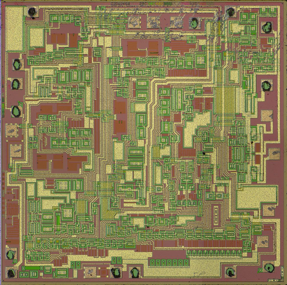
The edge length is 3,1mm.


CIC01498, a typical Burr-Brown naming.
And some masks revisions.


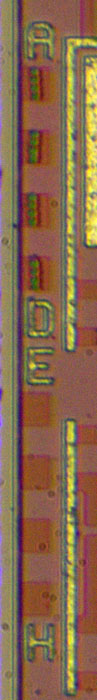
It looks like the eight squares were used to mark the tuning process...  :-/O


At some bondpads there are interesting small squares. Probably protection...


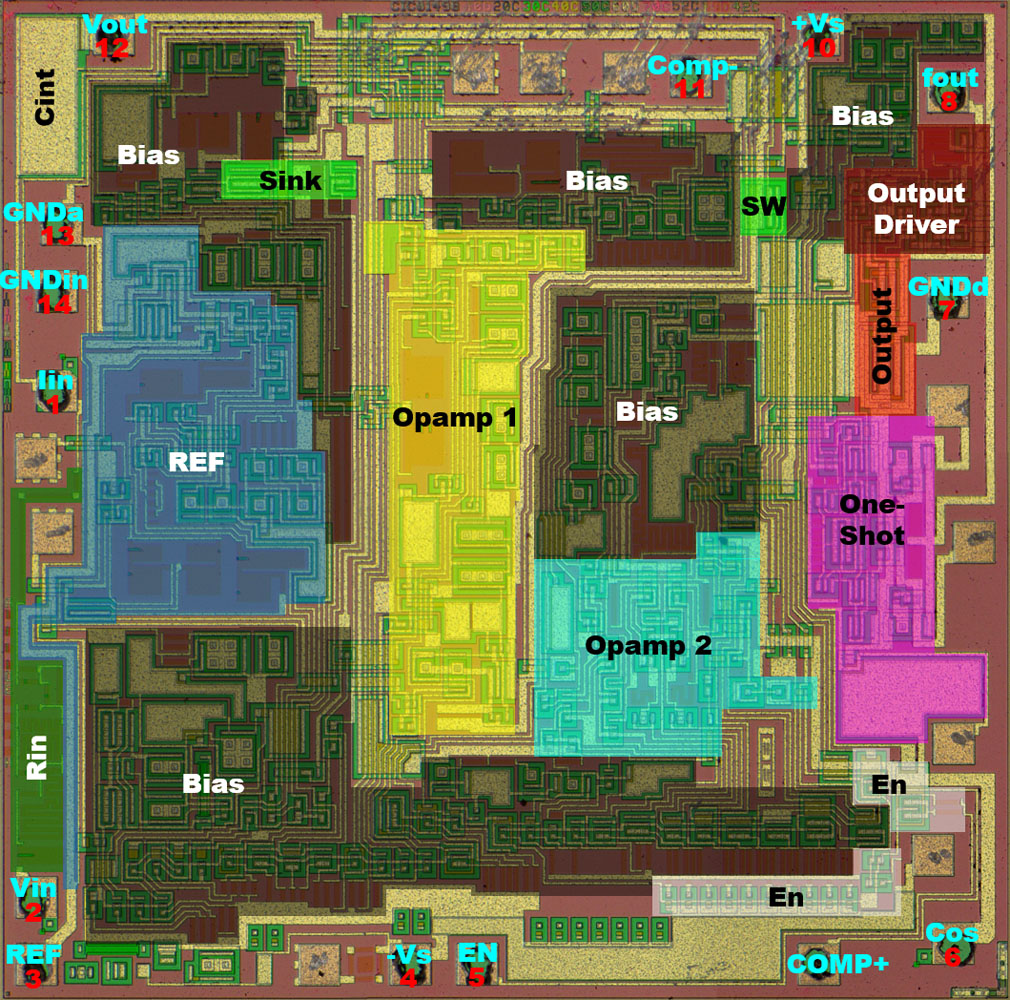
I´m not 100% sure but most functional blocks are easy to spot. Quite a lot of bias circuits.


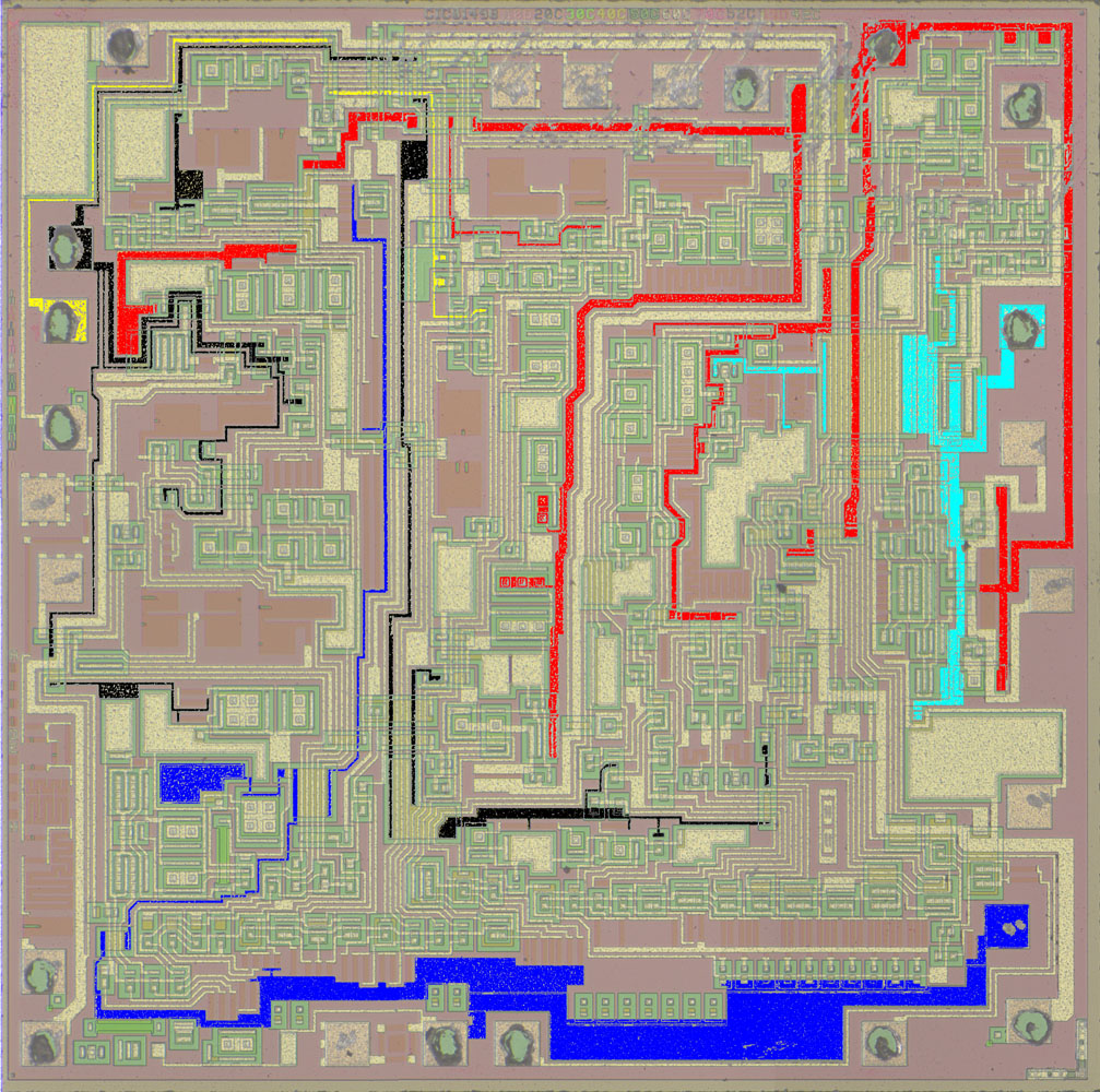
One metal layer and a lot of supply potentials.


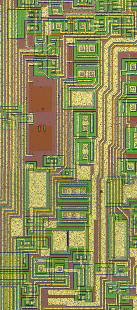
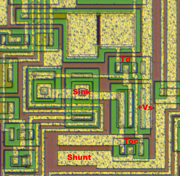
Now that are a lot of current sinks.


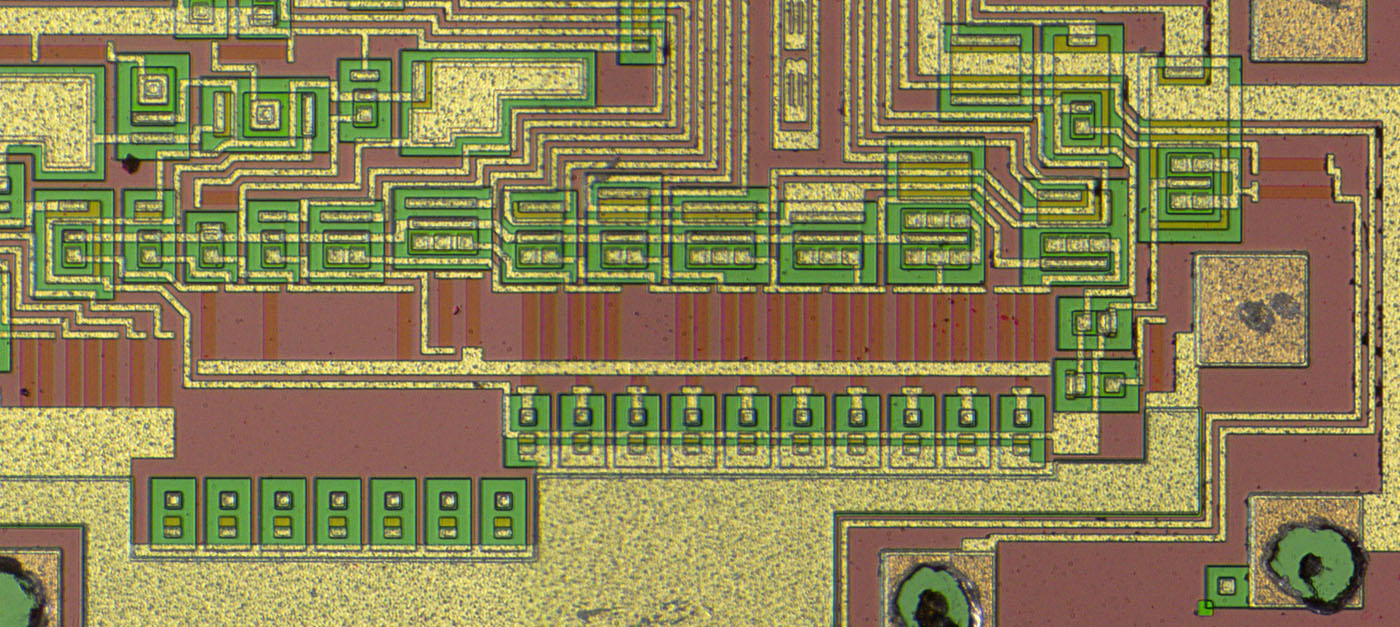
And a lot of the current sinks can be switched off with the enable pin.


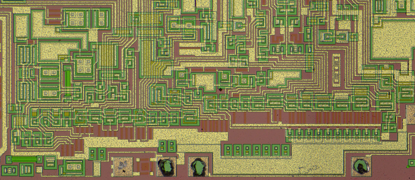
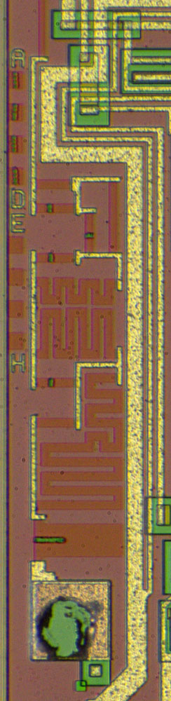
For the bias circuit BB integrated a bandgap reference.
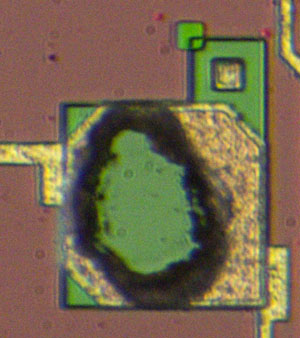
There is also an unused buried zener. Interesting... Perhaps they thought about using the zener for the bias circuit.


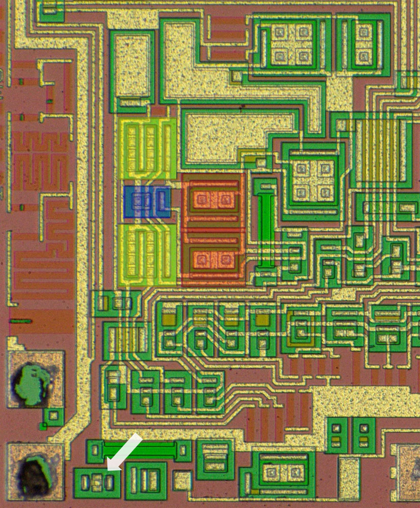
The reference voltage circuit.
At the top of the area is the output with overcurrent protection.
We have cross coupled transistor quads and dummy resistors.


The reference voltage output uses a sense line to compensate for the voltage drop.


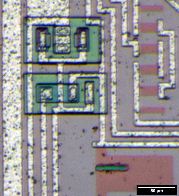
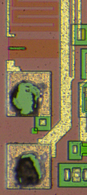
And here is the buried zener.


The input resistor is extensively tuned.


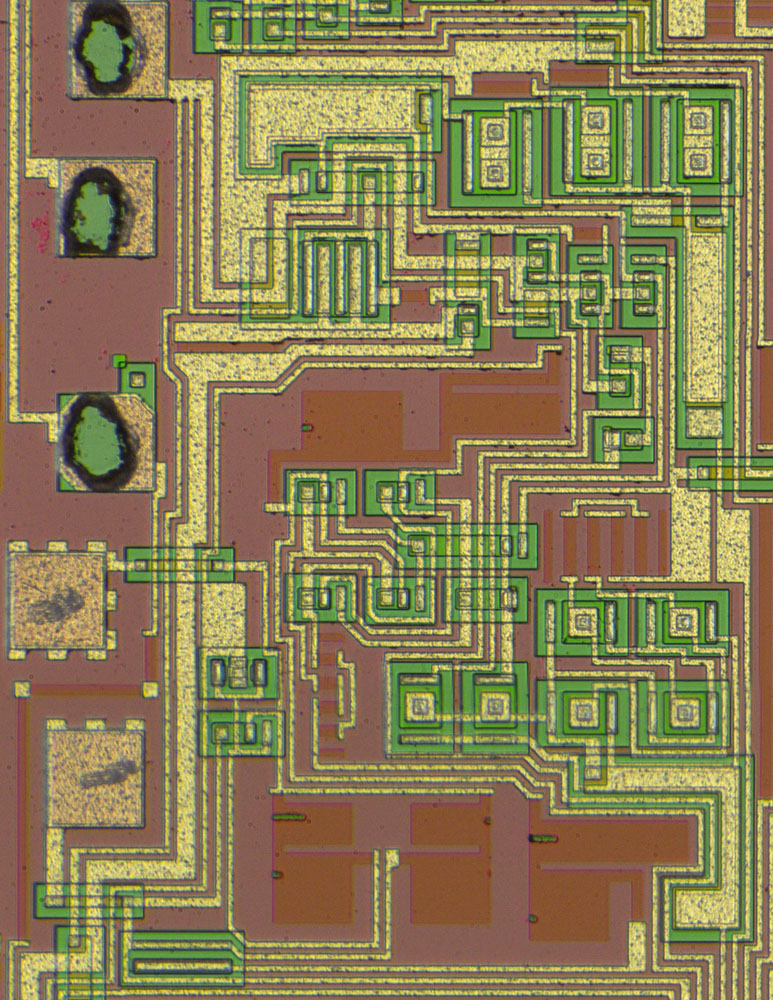
The first opamp, the integrator.


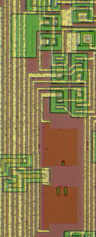
The opamp has diodes at the inputs. They prevent saturation and protect the input stage which is connected to the I_in pin.


The output is connected to the V_out pin and because of that it contains a "power transistor" and an overcurrent protection like in the reference circuit.


The second opamp is quite symmetrical.


The one-shot-circuit which controls the pulse width.
Below the circuit there is the internal Cos-capacitor. You can connect an additional external capacitor.


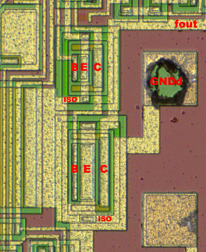
The output transistor is quite interesting. Around the active area there is an additional isolation frame ("iso") connected to GNDd. I assume the fast switching otherwise would causes a current flowing through the substrate to -Vs at the lower edge which could cause dirstubances in the other circuits.


More pictures here:

https://www.richis-lab.de/vfc01.htm

 :-/O
 
The following users thanked this post: doktor pyta, RoGeorge

Offline NoopyTopic starter

  • Super Contributor
  • ***
  • Posts: 1734
  • Country: de
    • Richis-Lab
Re: Different die pictures
« Reply #65 on: February 03, 2021, 10:44:11 pm »
Now that´s interesting:


KA610, a PCM30 repeater built in the GDR.
It is based on a HFO IA60 Master Slice, a generic die with a lot of transistors and resistors where you just have to develop the metal layer.
A more modern version of this concept can be seen in the OPA676: https://www.richis-lab.de/Opamp13.htm
The die is 2,6mm x 3,0mm. Since there was a big dot on the die it probably was rejected.


KA601 and a telephone...  :)


vertical npn transistor
With the four collector contacts you can route signals across a metal line. There is just one metal layer to connect all the necessary components.


npn power transistor


lateral pnp transistor
Here you can use the base contacts to wire a signal across a metal line.
The two collector contacts are isolated so you can´t use them for wiring signals but you can easily build a current mirror.  :-+


vertical substrate pnp transistor
Since the active areas are bigger and the distances are smaller than in the lateral pnp transistor the vertical pnp transistor provides a higher ft and more current amplification. But you have to accept the collector is connected to the substrate.
It´s interesting there is an additional p-doped area around the top edge. I assume that is to reduce collector resistance. If you put the heavily p-doped isolation area near the transistor you get quite a low breakdown voltage.


resistors


The resistor area is connected to a high potential to isolate the resistors against each other.


And a pinch resistor.
Here a n-doped layer narrows the p-doped resistor to get more resistance.
Interesting point: Under the left contact there is an area to connect the p-doped resistor and an area to connect to the n-doped area and the pinch layer.


https://www.richis-lab.de/KA601.htm


 :-/O
 
The following users thanked this post: brabus, RoGeorge

Offline brabus

  • Frequent Contributor
  • **
  • Posts: 326
  • Country: it
Re: Different die pictures
« Reply #66 on: February 04, 2021, 01:14:52 pm »
Impressive photos and impressive analysis!

Keep the good stuff coming! I always follow this thread with great interest.
 

Offline NoopyTopic starter

  • Super Contributor
  • ***
  • Posts: 1734
  • Country: de
    • Richis-Lab
Re: Different die pictures
« Reply #67 on: February 04, 2021, 02:24:02 pm »
Thanks for the positive feedback!
It´s always nice to hear that there are interested people reading my stuff.  :-+

Offline NoopyTopic starter

  • Super Contributor
  • ***
  • Posts: 1734
  • Country: de
    • Richis-Lab
Re: Different die pictures
« Reply #68 on: February 10, 2021, 09:46:48 pm »


Philips TDA1516, a 2x12W audio amplifier ideal for car applications (back in the days...  ;D).


The TDA1516 contains an interesting soft start circuit. There are two "input amplifiers". One is the real input amplifier which is switched on later and one does some precharging of the output amplifier and the coupling capacitors (if you need them). The precharge amplifier slowly ramps up the circuit to 0,5*Vp so you don´t get the switching "plop".

The TDA1516 has two pins supplying the driver circuit of the output stage. You can connect Vp to this pins. An alternative are bootstrapping capacitors to give the output a higher voltage range. With bootstraping you get the 24W otherwise only 22W.
Interesting fact: With bootstrapping you have to connect a 100k-resistor to pin 12. That gives you a little higher auxiliary voltage. Since the voltage amplifier probably inverts the signal the output is precharged to a somewhat lower voltage. That makes sense since the integrated bootstrap diode gives you a lower quiescent output voltage.

There is also a disconnect switch in the bootstrap circuit. Perhaps that was necessary to get the low quiescent current of 100µA.


There is something like a polyimid coating on the die.


The die is 3,1mm x 2,5mm.
You can see the power stage on the right and the rest of the circuit on the left.


The internal name of the design seems to be N4712B.
And Philips used two metal layers.


You can easily spot the lowside transistor (blue) and the highside transistor (red).
The lowside driver is a npn and therefore is quite small (purple).
The highside driver is a pnp and therefore is bigger (yellow).


Here you see the output stage transistors and their contacts to the metal layer.
The bootstrap potential takes quite an interesting way through the output stage.


pnp highside driver
I assume the two round transistors in the upper left corner of the metal rectangle are the bootstrap diode.


Hey, 10 base resistors for every transistor!  :-+


Input stage seems to be quite symmetrical but too much to read.  ;)


https://www.richis-lab.de/audioamp04.htm

 :-/O

Offline NoopyTopic starter

  • Super Contributor
  • ***
  • Posts: 1734
  • Country: de
    • Richis-Lab
Re: Different die pictures
« Reply #69 on: February 24, 2021, 08:44:53 pm »


Siemens S556, the controller of the worldwide first IR remote control used in a Grundig TV.


Minimum structure size seems to be around 8µm. Because of that the die is quite big: 4,6mm x 2,9mm
There is no datasheet but a press handout in which you can read that the S556 is built with PMOSFETs and depletion loads.
Two bondpads are not connected. The S556 was sold in a DIL16 and a DIL18 package which were able to read 8x4 keypad or a 6x4 keypad.


SVD-556 built by Siemens.


Five masks:
a: p-doped areas in the n-doped substrate
b: p-doping for depletion transistors between two p-doped areas
d: via for connecting the metal layer with the lower areas
e: metal layer (forms the gate electrodes over the gap between the p-doped areas)
f: windows in the passivation layer to connect the bondpads
In my view...


Now that´s an interesting structure under the bondpad... Perhaps some protection.
After a series resistor there is something like another protection or a pull-up-structure...


Test structure, image quality is not ideal.  :-\


https://www.richis-lab.de/S556.htm

 :-/O
« Last Edit: February 24, 2021, 08:46:33 pm by Noopy »
 
The following users thanked this post: SeanB

Offline NoopyTopic starter

  • Super Contributor
  • ***
  • Posts: 1734
  • Country: de
    • Richis-Lab
Re: Different die pictures
« Reply #70 on: March 08, 2021, 04:28:29 am »


Today I have something special for you: The U1001 is a NF-Filter for telephone systems developed in the GDR. It contains a HPF and a LPF for the transceiver and a LPF for the receiver. Interesting is the working principle of these filter stages. The U1001 uses switched capacitor filters which need less area than conventional filter stages and are tighter tolerated.


A nice big die: 5,9mm x 3,4mm
You can identify every functional block.


A telephone!  :-+


Input protection diodes...
The die was glued on a ceramic plate for many years. Because of that the structures are damaged a little.


SC-Filters need classical RC-Prefilters to prevent aliasing.


There are two polysilicon layers. That´s good for the capacitors. The red polysilicon layer in the middle is one plate of the capacitor while the green polysilicon layer and the metal layer are forming two plates above and under the red layer which gives you more capacitance.


Yeah the SC-Filter!  8)


Five opamps for the SC-Filter and one working as input buffer.
Above the opamps there are the capacitor switches.


Interesting: The SC-Filter doesn´t use the analog ground but gets a copy of the analog ground generated with the power supply.


The capacitors are built with a lot of small capacitors connected with small wires.
Why not one plane? Perhaps the wires add some damping so you don´t get ringing? Some capacitors are quite long...  :-//


Some red lines are shielded with the green layer.
Some capacitors are smaller...  :-//


The different planes set up 20 capacitors.


And a smoothing filter at the output to get rid of the switching noise.


Output opamp and input opamp.


The SC-HPF uses smaller capacitor structures. I don´t know why. All in all the filters are quite similar.


A defect!  :o
Here you can see the gate oxide sqare that increases the capacitance of the capacitors.


A lot of capacitors...


They did some tuning with fuses.


The second SC-LPF.


The two output opamps to get a differential signal. Back in the days they still had transducers in the system.


The two feedback resistors are quite interesting. Their ratio has to be constant so you don´t get a dc offset. The transducers wouldn´t like that.


A lot more pictures here:

https://www.richis-lab.de/phone01.htm

 :-/O
 
The following users thanked this post: SeanB, edavid, doktor pyta, RoGeorge

Offline NoopyTopic starter

  • Super Contributor
  • ***
  • Posts: 1734
  • Country: de
    • Richis-Lab
Re: Different die pictures
« Reply #71 on: March 13, 2021, 04:43:46 am »
Let´s take a look into a GMR tooth sensor module:


Sensitec GLM712
(picture taken from the datasheet)


The GLM712 contains two wheatstone bridges
(picture taken from the datasheet).


I own a manufacturing board where the sensor is still open. Here you see two sensors.


The metal seems to form the magnetic field. There is no magnet in there. The magnet would probably come in the next steps of the production.


The die is 2,17mm x 0,67mm.
Besides the 712 you can buy sensors for different tooth pitches.


The big parts are the GMR sensors. The wiring is interesting...


I assume the long closely wired connections compensate some trouble induced by the changing magnet field.


https://www.richis-lab.de/hall02.htm

 :-/O
 
The following users thanked this post: doktor pyta, RoGeorge, capt bullshot

Offline Renate

  • Super Contributor
  • ***
  • Posts: 1460
  • Country: us
Re: Different die pictures
« Reply #72 on: March 13, 2021, 12:31:51 pm »
 

Offline NoopyTopic starter

  • Super Contributor
  • ***
  • Posts: 1734
  • Country: de
    • Richis-Lab
Re: Different die pictures
« Reply #73 on: March 13, 2021, 12:55:34 pm »
I had never heard of GMR - https://en.wikipedia.org/wiki/Giant_magnetoresistance

Really? That was one milestone that enhanced the disk space of harddrives because the GMR can sense very small magnetic fields quite well.


Here you see an old inductive head (WD Caviar 22500 https://www.richis-lab.de/HDD_WD_Caviar_22500.htm).


And here you see a GMR-head with an inductive write coil and a GMR read element behind it. (Samsung SV4003H https://www.richis-lab.de/HDD_Samsung_SV4003H.htm)


The actual working principle is quite dizzying. Quantum mechanics...  :-//
 
The following users thanked this post: edavid, RoGeorge

Offline NoopyTopic starter

  • Super Contributor
  • ***
  • Posts: 1734
  • Country: de
    • Richis-Lab
Re: Different die pictures
« Reply #74 on: March 16, 2021, 05:02:01 am »


U114, a circuit built by Halbleiterwerk Frankfurt Oder to control an analog quarz alarm-clock.


The U114 contains a lot of frequency divider, two power stages for a clock stepper motor and one output stage for the alarm.
The U114 uses a 4,194304MHz quarz. Because of that you need more dividers leading to more current consumption than would be necessary with a 32,768kHz quarz. But it´s more accurate. The datasheet states 50µA without the motor while the U113 (32,768kHz) needs only a tenth of the current.


The die is 3,0mm x 1,8mm.


U114, that´s clear.
U4M39?  :-//


some test structures; 7 masks?


Here you can test three MOSFETs.


The two push-pull power stages are obvious. In the white area there seems to be driver circuit. The yellow power transistor controls the alarm.
Left and right of the power stages there are some columns with repetitive structures, probably containing the dividers.


The power transistor in detail.


In the lower right corner there is a structure near the quarz contacts which likely contains the oscillator circuit.


https://www.richis-lab.de/U114.htm

 :-/O
 
The following users thanked this post: SeanB, RoGeorge, Miyuki


Share me

Digg  Facebook  SlashDot  Delicious  Technorati  Twitter  Google  Yahoo
Smf