Author Topic: ESR Meter Adapter Design and Construction  (Read 164709 times)

0 Members and 1 Guest are viewing this topic.

Online kripton2035

  • Super Contributor
  • ***
  • Posts: 2587
  • Country: fr
    • kripton2035 schematics repository
Re: ESR Meter Adapter Design and Construction
« Reply #225 on: March 22, 2020, 06:20:26 pm »
well, I finally made my own jay_diddy_b's esr meter. wanted a digital one so I made this :


the inside mess :


measuring a capacitor, directly in ohms :


and comparing with a deree de5000 :
« Last Edit: March 22, 2020, 06:22:59 pm by kripton2035 »
 
The following users thanked this post: BravoV, Shock, edavid

Offline Shock

  • Super Contributor
  • ***
  • Posts: 4217
  • Country: au
Re: ESR Meter Adapter Design and Construction
« Reply #226 on: March 22, 2020, 08:29:39 pm »
Nice, had the same idea aside from the tweezers. There is a few broken image links in your post by the way.

How stable did the display turn out, would love to see a video of it.
Soldering/Rework: Pace ADS200, Pace MBT350
Multimeters: Fluke 189, 87V, 117, 112   >>> WANTED STUFF <<<
Oszilloskopen: Lecroy 9314, Phillips PM3065, Tektronix 2215a, 314
 

Online kripton2035

  • Super Contributor
  • ***
  • Posts: 2587
  • Country: fr
    • kripton2035 schematics repository
Re: ESR Meter Adapter Design and Construction
« Reply #227 on: March 22, 2020, 09:22:20 pm »
well if you measure a resistor, and your hands are steady, so is the last digit !
if you measure a capacitor, often bad ones, the last two digits can change a little.
I have added a small potentiometer to trim the output voltage, to take into account the probes resistance.
with it I can set the short probes to a fixed zero on the display.
but the amplify factor I would like also to trim it. it is ok from 0 to 1.5 ohm, but after that it degrades a little
a 10 ohms resistor is read ad 13 ohms. it is not important, but it would be so much better !
I can almost distinguish between a 0.01 and a 0.02 ohm resistor I have ! very nice.

I can see all the 4 pictures in my post. which one don't you see ?
 

Online kripton2035

  • Super Contributor
  • ***
  • Posts: 2587
  • Country: fr
    • kripton2035 schematics repository
Re: ESR Meter Adapter Design and Construction
« Reply #228 on: March 22, 2020, 10:08:11 pm »
this is the mod I made to the output opamp :
it let me setup a zero to cancel the probes resistance, with a very nice range using a multi-turn pot.
I would like to modify it to also handle the gain of the opamp, so that I can calibrate it, together with still zeroing it.
is it possible or must I add another opamp ?
« Last Edit: March 28, 2020, 09:38:20 pm by kripton2035 »
 

Offline AE7OO

  • Regular Contributor
  • *
  • Posts: 65
  • Country: us
Re: ESR Meter Adapter Design and Construction
« Reply #229 on: March 28, 2020, 09:11:41 pm »
I'm working on building the original meter with slight modification, I'm routing it today.
The modifications are different output and OSC, the blocking caps and going to 4 BNC connectors(So I can use the Kelvin clips I already have, I also have converters for regular probes). 

While the LT6241 is nice, I don't have any.  What I do have are a couple of ADA4807-1, which I used for the output.  For the OSC I went with a couple of inverters at about 200Khz, which I fed in to a string of SN74LVC1G80(single D FF) to get a 50% duty cycle.  I'll have the option to add a switch to control the frequency(i.e. I'll do the board to allow easy modification).

 The only high voltage caps I could find in the pulls drawer(I was not going order new) were 630V 3uF film caps.  Huge...  And so while the original called for .1u and .01u, what it got was 3u.  If nothing else this should allow me to add a much lower frequency if I need to.

*******
At the same time I'm looking into doing one that will use a sine wave.

I was thinking to use a biased non-inverting schmitt buffer to generate the in-phase square wave.  The specific chip I was going to use was the dual buffer NL27WZ17(LVC compatiable).   With a 3.1 ns typical delay, it should be transparent and placing it within millimeters of the switch input should allow me to ignore the signal edges.

I also have single inverting and non-inverting schmitt buffers available(these are actually multi-function gates, but same speeds) if need be.

Does anyone see any problems doing it this way? 
LTSpice generates the same waveform at the output(using the generic schmitt buffer) so I think that I'm in at least the same ballpark.
 

Offline hugo

  • Regular Contributor
  • *
  • Posts: 165
  • Country: ca
Re: ESR Meter Adapter Design and Construction
« Reply #230 on: March 28, 2020, 10:39:51 pm »
Quote
well, I finally made my own jay_diddy_b's esr meter. wanted a digital one so I made this :

What is the current drawn by the digital voltmeter?

Thanks
« Last Edit: March 29, 2020, 02:51:20 pm by hugo »
 

Offline Jay_Diddy_BTopic starter

  • Super Contributor
  • ***
  • Posts: 2733
  • Country: ca
Re: ESR Meter Adapter Design and Construction
« Reply #231 on: March 28, 2020, 11:29:02 pm »
While the LT6241 is nice, I don't have any.  What I do have are a couple of ADA4807-1, which I used for the output.  For the OSC I went with a couple of inverters at about 200Khz, which I fed in to a string of SN74LVC1G80(single D FF) to get a 50% duty cycle.  I'll have the option to add a switch to control the frequency(i.e. I'll do the board to allow easy modification).


The ADA4807-1 will work fine as the output amplifier.

The circuit will work, unmodified with the LTC6241 replaced by the ADA4807-2 (dual version)

The use of a logic oscillator at 2x frequency followed by a flip-flop will be fine.

The only high voltage caps I could find in the pulls drawer(I was not going order new) were 630V 3uF film caps.  Huge...  And so while the original called for .1u and .01u, what it got was 3u.  If nothing else this should allow me to add a much lower frequency if I need to.


This is a bad idea. The resistor in series with the capacitors will be damaged by the surge if you connect the ESR meter adapter to a high voltage (or a capacitor charged with a high voltage).

Look for old switch mode power supplies. use the X-cap (Line to Neutral) for the 0.1uF position. Use the y-cap  (Lines to GND) for the 0.01uF capacitor. The circuit will work with 4700pF (or 2x 2200pf in parallel) in this position.

Looking forward to seeing your version.

Best regards,

Jay_Diddy_B


Online kripton2035

  • Super Contributor
  • ***
  • Posts: 2587
  • Country: fr
    • kripton2035 schematics repository
Re: ESR Meter Adapter Design and Construction
« Reply #232 on: March 29, 2020, 08:41:07 am »
 

Offline MiroS

  • Regular Contributor
  • *
  • Posts: 157
  • Country: pl
Re: ESR Meter Adapter Design and Construction
« Reply #233 on: March 29, 2020, 03:08:33 pm »
Do you know if anyone created Kicad schematics and PCB ?

I just started to test Kicad and created one,  no footprint assigned, only raw schematics.
« Last Edit: March 29, 2020, 05:32:50 pm by MiroS »
 

Offline AE7OO

  • Regular Contributor
  • *
  • Posts: 65
  • Country: us
Re: ESR Meter Adapter Design and Construction
« Reply #234 on: March 29, 2020, 05:37:58 pm »
Thanks for the reply.

Quote
This is a bad idea. The resistor in series with the capacitors will be damaged by the surge if you connect the ESR meter adapter to a high voltage (or a capacitor charged with a high voltage).

Are you talking about R15 and R16?  If so, would going to a power resistor for those help? 

What is the largest value  that I can get away with for C5 and C6?  I would love to be able to test something at ~1.5Khz if I wished.  Since I'm already using a FF to get my 100Khz, I was going to go ahead and lay down a string of 4 or 5 of them.  So in the future it would be easy to add a switch and test at the divide freqs.(i.e. 50, 25, etc).   Or just 100/1.

Quote
Look for old switch mode power supplies. use the X-cap (Line to Neutral) for the 0.1uF position. Use the y-cap  (Lines to GND) for the 0.01uF capacitor. The circuit will work with 4700pF (or 2x 2200pf in parallel) in this position.

Would 2 caps in series or parallel at the C5 or C6 position cause a problem for the circuit?

Quote
Looking forward to seeing your version.

I'm not sure I'll let a schematic out(they work for me, but some may not like the style), but I'll post some pictures of the boards no problem.

And thank you for both the reply and posting the project to begin with.

GB

Oh, afterthought.  Would you mind commenting on my linked square wave generation method?
Thanks!
« Last Edit: March 29, 2020, 05:39:59 pm by AE7OO »
 

Online trobbins

  • Frequent Contributor
  • **
  • Posts: 765
  • Country: au
Re: ESR Meter Adapter Design and Construction
« Reply #235 on: March 29, 2020, 06:40:31 pm »
I just found I had a small stash of HEF4053B, so am going to set up a diy adaptor too.  The HEF4053 allows a higher supply voltage from 2x 9V batteries to get say +/- 6V supply, but I may initially just aim for 10kHz and then check if 100kHz performs ok.

I also have a spare AD521 and 524 so will see how a vintage IA goes for trimmable offset and gain (and perhaps use its x10, x100 and x1000 programmed gains and an output level trimpot for different ESR ranges).
« Last Edit: March 29, 2020, 06:45:41 pm by trobbins »
 

Offline Jay_Diddy_BTopic starter

  • Super Contributor
  • ***
  • Posts: 2733
  • Country: ca
Re: ESR Meter Adapter Design and Construction
« Reply #236 on: March 29, 2020, 07:39:57 pm »
I just found I had a small stash of HEF4053B, so am going to set up a diy adaptor too.  The HEF4053 allows a higher supply voltage from 2x 9V batteries to get say +/- 6V supply, but I may initially just aim for 10kHz and then check if 100kHz performs ok.

I also have a spare AD521 and 524 so will see how a vintage IA goes for trimmable offset and gain (and perhaps use its x10, x100 and x1000 programmed gains and an output level trimpot for different ESR ranges).

Hi,

Check this message regarding the selection of the 4053 mux.

https://www.eevblog.com/forum/projects/esr-meter-adapter-design-and-construction/msg341346/#msg341346

Regards,

Jay_Diddy_B
 

Online trobbins

  • Frequent Contributor
  • **
  • Posts: 765
  • Country: au
Re: ESR Meter Adapter Design and Construction
« Reply #237 on: March 30, 2020, 12:00:40 am »
Ta thanks - yes I had read the thread and noted the likely issue of speed, so will initially go for 10kHz and see how influential the type of 4053 is (I am getting some possibly slower CD4053 in at some time, but not a 74HC4053).  It is a little difficult comparing timing specs for address changes, as output loading conditions seem to be a bit different between the datasheets, and the application appears to have substantially different loading conditions (much higher load capacitance).

Was the S2 switch in the 4053 connected to toggle with the oscillator for convenience in routing, as compared to being configured to be idle?

Apart from being cheaper parts, the HEF and CD4053 allow a higher working voltage (which needs to be used to reduce the delay/transition times), and could therefore have some benefits for stand-alone testing of caps (compared to in-situ pcb testing where there may be semiconductor junctions imposing themselves on a measurement). 

I aim to construct the 4053 end on a DIP-to-soic header board (for convenience), and use a pre-existing measurement board with the IA, so hope to make the 4053 end and the gain end swappable to do some comparisons.

Ciao, Tim
« Last Edit: March 30, 2020, 12:03:55 am by trobbins »
 

Offline Jay_Diddy_BTopic starter

  • Super Contributor
  • ***
  • Posts: 2733
  • Country: ca
Re: ESR Meter Adapter Design and Construction
« Reply #238 on: March 30, 2020, 12:53:06 am »
Tim,


If you mean the part of the 4053 that is on the left side of the circuit, it is there to match the delays with the switch on the right side of the circuit.

Regards,

Jay_Diddy_B
 

Offline Jay_Diddy_BTopic starter

  • Super Contributor
  • ***
  • Posts: 2733
  • Country: ca
Re: ESR Meter Adapter Design and Construction
« Reply #239 on: March 30, 2020, 02:45:09 am »
Do you know if anyone created Kicad schematics and PCB ?

I just started to test Kicad and created one,  no footprint assigned, only raw schematics.

MiroS,

I have had a look at your KiCAD schematic. I have found a few issues:


In this section there is a missing connection between the two 3.32k \$\Omega\$ resistors and the capacitor.
The capacitors should be ceramic. They need to be low ESR.


In this section C6 should be 0.01uF or 10nF

R16 should be 10 \$\Omega\$

Just so you know, R21 was in the original design as a jumper. It allow the circuit to be constructed single-sided with no vias.

Regards,

Jay_Diddy_B
 
The following users thanked this post: MiroS

Online trobbins

  • Frequent Contributor
  • **
  • Posts: 765
  • Country: au
Re: ESR Meter Adapter Design and Construction
« Reply #240 on: March 30, 2020, 03:59:47 am »
If you mean the part of the 4053 that is on the left side of the circuit, it is there to match the delays with the switch on the right side of the circuit.
Soz, I was referring to all the circuitry to the left of the gain stage.  As you have identified, analog switch operation within the same IC package should have close switch time matching, and so aligned synchronous detection.

I just found I also had 2 samples of TS5A22362, which appears to be pretty similar to the 74HC4053, and with only two spdt switches - so likely well suited to this application.

Nearly two decades ago we used a similar scheme to extract the real part of battery impedance by injecting a sine current in to large lead-acids, and used an AD630 for the demod to extract a valid signal out of a lot of noise.  The AD630 isn't a cheap IC, and unfortunately I don't have any lying around.

Tim
 

Offline MiroS

  • Regular Contributor
  • *
  • Posts: 157
  • Country: pl
Re: ESR Meter Adapter Design and Construction
« Reply #241 on: March 30, 2020, 06:09:17 am »
Thanks Jay_Diddy_B, corrections and footprints included.
 

Online kripton2035

  • Super Contributor
  • ***
  • Posts: 2587
  • Country: fr
    • kripton2035 schematics repository
Re: ESR Meter Adapter Design and Construction
« Reply #242 on: March 30, 2020, 06:36:14 am »
@MiroS: you should provide the libraries you used for the schematic because when I open your file, I get this :


Offline MiroS

  • Regular Contributor
  • *
  • Posts: 157
  • Country: pl
Re: ESR Meter Adapter Design and Construction
« Reply #243 on: March 30, 2020, 01:23:36 pm »
I am using Kicad Version: (5.1.5)-3, release build
No custom parts, all from standard libraries

My local project folder is
C:\Users\M\Documents\ESR_Tester_SMD\ESR_Tester_SMD.pro

I am attaching complete folder content, including  main archive  file  created  by Kicad itself - menu File -> Archive Project.
ESR_Tester_SMD_v0.zip.
« Last Edit: March 30, 2020, 01:25:13 pm by MiroS »
 

Online kripton2035

  • Super Contributor
  • ***
  • Posts: 2587
  • Country: fr
    • kripton2035 schematics repository
Re: ESR Meter Adapter Design and Construction
« Reply #244 on: March 30, 2020, 02:09:18 pm »
it's ok now, even though I have an older kicad version.
 

Offline X.G.

  • Newbie
  • Posts: 5
  • Country: cn
Re: ESR Meter Adapter Design and Construction
« Reply #245 on: April 01, 2020, 08:27:21 am »
the ESR Meter Adapter Design which come from China,and only use one IC.

it can display the value of resistor,the ESR of cap,and the value of inductance.the  IC  is TDA1308,NE5532 or TL082.TDA1308 can work at 3~5V,NE5532 can work at 5~9V.

http://www.crystalradio.cn/forum.php?mod=viewthread&tid=683954

http://www.crystalradio.cn/forum.php?mod=viewthread&tid=683954&extra=&page=1


« Last Edit: April 01, 2020, 09:09:46 am by X.G. »
 

Offline Jay_Diddy_BTopic starter

  • Super Contributor
  • ***
  • Posts: 2733
  • Country: ca
Re: ESR Meter Adapter Design and Construction
« Reply #246 on: April 03, 2020, 02:14:05 am »
Hi X.G. and the group,

This is an interesting circuit that has been shared by X.G.

I am particularly interested in the oscillator portion of the circuit built around Q1 and Q2. There are some comments in crystalradio forum (Thanks to Google Translate) that talk about this oscillator. The crystalradio forum talks about using different values of resistors in the oscillator.

For the circuit to work the oscillator has to generated a fixed amplitude sinewave at around 100kHz.

I first ran a simulation:


And I get the result:


Which is great!!

A little board was designed for a hardware test:


I built the board:


Using this inductor:


And I measured this output:


The waveform amplitude is much lower than the LTspice model.

To be continued …

Jay_Diddy_B
« Last Edit: April 03, 2020, 02:40:05 am by Jay_Diddy_B »
 

Offline Jay_Diddy_BTopic starter

  • Super Contributor
  • ***
  • Posts: 2733
  • Country: ca
Re: ESR Meter Adapter Design and Construction
« Reply #247 on: April 03, 2020, 02:39:00 am »
Hi,

I modified the LTspice model to include the resistance of the inductor:


The results of this are:


This shows how the amplitude of the oscillation changes as a function of AC resistance in the inductor.

Improvement

Change the inductor to 100uH and the capacitor to 22nF:


The results are:


There is much reduced sensitivity to the resistance of the inductor.

Hardware Test:

Here is a picture of the 100uH board:


This is the inductor, from Wurth:


And the test results:


The amplitude is 1.4V (2x Vbe) as predicted by LTspice.

The 100uH and 22nF are much better choices for this circuit.

Regards,

Jay_Diddy_B


The following users thanked this post: kripton2035

Offline X.G.

  • Newbie
  • Posts: 5
  • Country: cn
Re: ESR Meter Adapter Design and Construction
« Reply #248 on: April 03, 2020, 09:24:04 am »
I experimented  the style circuit of OSC in my analogue ESR meter  in July 2016.

http://www.crystalradio.cn/forum.php?mod=viewthread&tid=1623736&extra=


my notebook show the simple test  before 3 years:

1.my final selects  are  R1=51 ohms, L1=40uH(6 turns),in the circuit work at 1.0V~1.5V.

2.when R1=22 ohms, the sine shape change,trending  to be a square(THD is higher).

3.when R1=68 ohms,the sine shape is better(THD is lower),the amplitude  reduced ,and the amplitude  reduced much than R1=51 with  lower Vcc.

4.when L1=160uH(12 turns),the wave of OSC  is likely  square.

5.I think that the open-loop gain of OSC=AC resistance of inductor/R1,so I tried to add a resistor less than 100 ohms ,paralleling with L1, for lowering the the open-loop gain,and  the OSC wave shape became better,just like highering R1.


« Last Edit: April 03, 2020, 09:26:00 am by X.G. »
 

Online trobbins

  • Frequent Contributor
  • **
  • Posts: 765
  • Country: au
Re: ESR Meter Adapter Design and Construction
« Reply #249 on: May 08, 2020, 12:02:31 pm »
Just starting to gather parts and prepare circuitry sections now for a variant of Jay_Diddy_B's ESR meter.

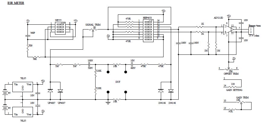
I have plenty of HEF4053BT, so am going to see how this fairs up to 100kHz, given a higher supply rail of 10V to improve switching speed and on-resistance.

I also have a few vintage instrumentation opamps on pcbs, so will re-purpose an AD521 and hopefully achieve 1V/ohm scaling with zero offset, and maybe allow a 10:1 gain switch for higher ESR levels.

Aiming to see if the spare 4053 switch can operate in parallel for the voltage signal switch, to minimise the switch resistance a bit more (and hopefully not experience any switching glitches).

As this will be more of a bench speciality module, I don't mind using two 9V batteries and each 5V reg will compensate for its own battery and not need any loading for mid-point management.

I have a batch of 47milliohm 1% SMD, and 1 ohm 1% leaded, to make up a set of calibration resistors (which is timely, as my next activity it to restore a Pontavi Th2 milliohmeter).


Share me

Digg  Facebook  SlashDot  Delicious  Technorati  Twitter  Google  Yahoo
Smf