Author Topic: Ultra low power microcontroller design - LCD Clock  (Read 16456 times)

0 Members and 1 Guest are viewing this topic.

Offline HowardlongTopic starter

  • Super Contributor
  • ***
  • Posts: 5319
  • Country: gb
Ultra low power microcontroller design - LCD Clock
« on: January 02, 2017, 11:31:13 pm »
Edit 15 Jan 2022: see also updated sub microwatt version here: https://www.eevblog.com/forum/projects/ultra-low-power-mcu-design-the-nanowatt-clock/

https://youtu.be/yyoR0o5YBVI

Aim: make a useful microcontroller project that will work in under 1uA aggregate current, to be powered by one or two of those tritium/solar cells that Nurd Rage built.

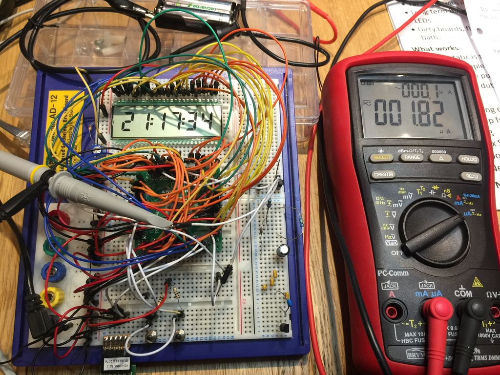
Result: An LCD clock is close, it worked, but not quite sub 1uA. Despite a lot of work, 1.8uA was the best I managed, so about 100+ years on a pair of AAs if they didn't self discharge and leak all over the place beforehand.

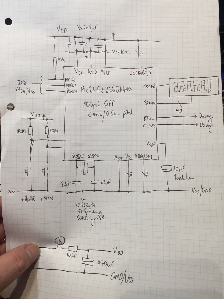
It's based on PIC24FJ256GA410 Nanowatt XLP processor. i couldn't achieve one or two of the datasheet delta current specs by some way, particularly the low voltage sleep current by an order of magnitude (60nA spec'd, 550nA achieved), others weren't spec'd or occasionally I achieved better.

What I learned...

O Don't trust all datasheet and marketing specs;
O Prototype everything first (I knew this already, this just reinforces it);
O Clean your boards or your current measurements are shit with ultra low power stuff;
O Closely follow crystal specs and layout for ultra low power oscillators;
O Measure high dynamic range very low duty cycle aggregate current, and it's not the uCurrent (at least not on its own).
O Remove your debugging/programming tool when taking current measurements.

Non-junk box parts:
o Microchip PIC24FJ256GA410-I/PT Farnell ref 2493343
o Abracon ABS25-32.768KHZ-T Farnell ref 1611824
o LCD Clover Display 5042PHR www.rs-online.com ref 184-7737


Oscillator startup times from cold power up, VDD yellow, 8MHz FRC green, 32.768kHz crystal oscillator blue. Note that I modified the code to output the SOSC on a buffered REFO pin as probing the SOSC low power oscillator crystal directly is extremely difficult to do without stopping the oscillator. Even spring grounded techniques with Tek 3.9pF/10Mohm load passive probes, or 0.6pF/0.3pF single ended/differential 100kohm FET browser probes stopped the oscillator.


The low power secondary oscillator is very picky about crystals, 0402 22pF loading caps and parasitics, so I soldered them directly on the breakout board and isolated the two SOSC pins from the breadboard by cutting the tracks. There is a ground adjacent to one of the SOSC pins where both the caps terminate. The device's pitch here is 0.4mm to give a sense of scale. Not sure if the obligatory cat hair has any beneficial effect. I know it's not one of mine, I'm bald as a coot.


« Last Edit: January 15, 2022, 11:45:53 pm by Howardlong »
 
The following users thanked this post: thmjpr, edavid, TechnicalBen

Offline edavid

  • Super Contributor
  • ***
  • Posts: 3383
  • Country: us
Re: Happy Nerd Year! My first project of the year, semi fail.
« Reply #1 on: January 02, 2017, 11:43:33 pm »
Nice!

What's the current with the LCD disconnected?
 

Offline kiran_shrestha

  • Regular Contributor
  • *
  • Posts: 62
  • Country: kr
  • Kiran
    • shorted wire
Re: Happy Nerd Year! My first project of the year, semi fail.
« Reply #2 on: January 03, 2017, 01:20:30 am »
I suggest to go paper displays , as do not eat any current when display is not updating and remove the "seconds" part of the circuit and update only at a minute. You can get oh very less current and hell long life.
-------------------------------------------------------------
Thats all
 

Online Ian.M

  • Super Contributor
  • ***
  • Posts: 12856
Re: Happy Nerd Year! My first project of the year, semi fail.
« Reply #3 on: January 03, 2017, 01:35:19 am »
A common cause of PIC MCUs not meeting sleep mode current specs even though all possible optional modules have been powered down, and no inputs have been left floating, is ESD damage.
 
The following users thanked this post: rs20

Offline HowardlongTopic starter

  • Super Contributor
  • ***
  • Posts: 5319
  • Country: gb
Re: Happy Nerd Year! My first project of the year, semi fail.
« Reply #4 on: January 03, 2017, 06:25:06 am »
A common cause of PIC MCUs not meeting sleep mode current specs even though all possible optional modules have been powered down, and no inputs have been left floating, is ESD damage.

All done. Moved on quite away from that stage I'm afraid. In this case, I am fairly sure there's a typo in the device's data sheet. The low voltage sleep mode shows less than for deep sleep, and he difference between 25 deg C and 60 deg C is over 50 times, 60nA to 3.6uA. I get around 550nA with all peripherals off, both WDTs off, all BORs off, all oscilators off, all I/Os force low in low voltage sleep. I even went as far as suspecting cap leakage. The biggest delta was to get the breakout board cleaned, went from 3uA or so down to 500nA. I knew something wasn't right as I could get a DIP device plugged to the breadboard down to 100nA or so deep sleep on a PIC24F08KA102.

I couldn't get deep sleep to work as specified either on the LCD device, about 5uA compared to 100nA in the data sheet. Not much use anyway, the LCD wouldn't work in deep sleep.
 

Offline HowardlongTopic starter

  • Super Contributor
  • ***
  • Posts: 5319
  • Country: gb
Re: Happy Nerd Year! My first project of the year, semi fail.
« Reply #5 on: January 03, 2017, 06:27:16 am »
I suggest to go paper displays , as do not eat any current when display is not updating and remove the "seconds" part of the circuit and update only at a minute. You can get oh very less current and hell long life.

I's already looked but the ones I found were far more power hungry than a static LCD. Do you have a device in mind?
 

Offline HowardlongTopic starter

  • Super Contributor
  • ***
  • Posts: 5319
  • Country: gb
Re: Happy Nerd Year! My first project of the year, semi fail.
« Reply #6 on: January 03, 2017, 06:34:43 am »
Nice!

What's the current with the LCD disconnected?

It's about 300nA for the display depending on the number of segments that are on, and 400nA for the LCD peripheral depending in the speed it's running (16Hz here). Using a smaller (lower capacitance) display and fewer segment would, of course, reduce this. By using only four digits, and therefore only updating the display every minute and not flashing the colons every half second would also be pretty beneficial as the device would only be waking up 1/120th of the time.
 

Offline richardlawson1489

  • Regular Contributor
  • *
  • Posts: 124
  • Country: us
    • PCB Assembly
Re: Happy Nerd Year! My first project of the year, semi fail.
« Reply #7 on: January 03, 2017, 01:51:45 pm »
Happy Nerd Year! Nice project. I would love to know more about your project.
 

Offline HowardlongTopic starter

  • Super Contributor
  • ***
  • Posts: 5319
  • Country: gb
Re: Happy Nerd Year! My first project of the year, semi fail.
« Reply #8 on: January 03, 2017, 02:57:29 pm »
Happy Nerd Year! Nice project. I would love to know more about your project.

I have done a video on it but five minutes of it need re-shooting as it was out of focus. I'll publish the URL here in the next day or so.
 

Offline HowardlongTopic starter

  • Super Contributor
  • ***
  • Posts: 5319
  • Country: gb
Re: Ultra low power microcontroller design - LCD Clock
« Reply #9 on: January 04, 2017, 09:22:29 am »
I've updated the original post:

o Embedded the video;
o Added a picture of the basic schematic;
o Added three attachments including two source files and the spreadsheet I used to hook up the LCD, and generate code to paste into C source files;
o Amended title.
 
The following users thanked this post: slicendice

Online BrianHG

  • Super Contributor
  • ***
  • Posts: 7732
  • Country: ca
Re: Ultra low power microcontroller design - LCD Clock
« Reply #10 on: January 04, 2017, 10:50:29 am »
For my PIC battery powered projects, having it on my bread-board also drew extra current.  In fact, the bread board's extra current draw swung widely with a slight change in ambient temperature, as did the prototype PCBs until I remover and replaced the PIC, scraped traces between IO pins and finally cleaned everything over & over again with a electric sonic vibrating toothbrush and cleaning solvents.  It took time, but, I finally did manage to get the battery power consumption down to sub 20ua where I needed it. (note this was 2002 and 20ua on a a pic + and active IR receiver was considered great back then).

« Last Edit: January 04, 2017, 10:53:29 am by BrianHG »
 

Offline jdraughn

  • Regular Contributor
  • *
  • Posts: 106
Re: Ultra low power microcontroller design - LCD Clock
« Reply #11 on: January 04, 2017, 10:57:32 am »
What voltage are you running at? Maybe the current draw in the datasheet is based on a lower voltage then what your using?
 

Online BrianHG

  • Super Contributor
  • ***
  • Posts: 7732
  • Country: ca
Re: Ultra low power microcontroller design - LCD Clock
« Reply #12 on: January 04, 2017, 11:15:29 am »
About voltage regulators in Howardlong's video.

For ultra low power regulator with a good 25v input range, I use a simple N-Channel J-fet with the gate tied to GND, the source is your output and the drain goes to your power source.  The 0 load current of the J-fet regulator should be in the picoamp range or less with a dropout voltage range of 0.  The vgs of the Jfet you choose determines the output voltage.  This solution works great for apps below 10ma.  The cons is that the Jfet's vgs isn't precise from part to part, however, usually for these PICs, this isn't too much a problem.

 
The following users thanked this post: richard.cs

Online BrianHG

  • Super Contributor
  • ***
  • Posts: 7732
  • Country: ca
Re: Ultra low power microcontroller design - LCD Clock
« Reply #13 on: January 04, 2017, 11:25:42 am »
From video: Measuring current with Dave's uCurrent board, getting rid of those current peaks.

Just tie a 1000uf, or, 10000uf cap, or larger, right on the terminals, in parallel across the + / -  current input.  This removes the peaks & you can now choose an averaging filter of your choice to smooth out the current spikes when the CPU goes in and out of sleep.
 

Offline HowardlongTopic starter

  • Super Contributor
  • ***
  • Posts: 5319
  • Country: gb
Re: Ultra low power microcontroller design - LCD Clock
« Reply #14 on: January 04, 2017, 11:26:08 am »
About voltage regulators in Howardlong's video.

For ultra low power regulator with a good 25v input range, I use a simple N-Channel J-fet with the gate tied to GND, the source is your output and the drain goes to your power source.  The 0 load current of the J-fet regulator should be in the picoamp range or less with a dropout voltage range of 0.  The vgs of the Jfet you choose determines the output voltage.  This solution works great for apps below 10ma.  The cons is that the Jfet's vgs isn't precise from part to part, however, usually for these PICs, this isn't too much a problem.

Nice tip! My point is around reasonably accurate generation of bias voltages that inevitably involves some current, and that's why integrated voltage regulators tend to have significant quiescent currents in these applications.
 

Offline HowardlongTopic starter

  • Super Contributor
  • ***
  • Posts: 5319
  • Country: gb
Re: Ultra low power microcontroller design - LCD Clock
« Reply #15 on: January 04, 2017, 11:29:21 am »
From video: Measuring current with Dave's uCurrent board, getting rid of those current peaks.

Just tie a 1000uf, or, 10000uf cap, or larger, right on the terminals, in parallel across the + / -  current input.  This removes the peaks & you can now choose an averaging filter of your choice to smooth out the current spikes when the CPU goes in and out of sleep.

That was my original solution, but it doesn't work. You need an RC solution as I explained in the video I'm afraid. And you need to take care that the leakage in your cap is minimal (or model it out). In the vid I used a 10k and 470uF which had sub 100nA leakage current at the operating voltage.
 

Online BrianHG

  • Super Contributor
  • ***
  • Posts: 7732
  • Country: ca
Re: Ultra low power microcontroller design - LCD Clock
« Reply #16 on: January 04, 2017, 11:38:38 am »
That was my original solution, but it doesn't work. You need an RC solution as I explained in the video I'm afraid. And you need to take care that the leakage in your cap is minimal (or model it out). In the vid I used a 10k and 470uF which had sub 100nA leakage current at the operating voltage.

Yup, sorry, I see that now.  My recent emergency 1 pulse every 5 sec LED sign with spikes at 2 amps for .025 sec avg, then sleeps, had also had a 220000uf cap in on the power with 10 ohm series.  I forgot about it.  (Damn thing took 1/2 hour to stabilize my true average current readings...)
 

Offline HowardlongTopic starter

  • Super Contributor
  • ***
  • Posts: 5319
  • Country: gb
Re: Ultra low power microcontroller design - LCD Clock
« Reply #17 on: January 04, 2017, 12:43:04 pm »
What voltage are you running at? Maybe the current draw in the datasheet is based on a lower voltage then what your using?

2.5V, but if you watch the video you'll see I account for that.
 

Offline HowardlongTopic starter

  • Super Contributor
  • ***
  • Posts: 5319
  • Country: gb
Re: Ultra low power microcontroller design - LCD Clock
« Reply #18 on: January 09, 2017, 07:10:31 pm »
o Added a scope screenshot of the internal FRC oscillator and low power crystal startup times.

o Added two pics showing the 32.768kHz crystal and 22pF loading caps, together with PCB mods/hacks to the breakout board.


Offline mikeselectricstuff

  • Super Contributor
  • ***
  • Posts: 13745
  • Country: gb
    • Mike's Electric Stuff
Re: Ultra low power microcontroller design - LCD Clock
« Reply #19 on: January 09, 2017, 08:05:37 pm »
Haven't watched the vid but....
I'd have used a 10u ceramic rather than a 4u7 tant - potentially less leakage.
Also 10M on the buttons is high for a pullup - could get into floaty-input territory- I'd use a lower pullup, switched on & off as necessary. Power draw when switches are on isn't going to be a big deal anyway. If it's a concern due to peak current, maybe use interrupt-on-change to switch off the pullup as soon as switch is detected, then polling to detect release.
How low did you take the LCD frequency? Driving the LCD capacitance will be a significant part of the current draw


Youtube channel:Taking wierd stuff apart. Very apart.
Mike's Electric Stuff: High voltage, vintage electronics etc.
Day Job: Mostly LEDs
 

Offline HowardlongTopic starter

  • Super Contributor
  • ***
  • Posts: 5319
  • Country: gb
Re: Ultra low power microcontroller design - LCD Clock
« Reply #20 on: January 10, 2017, 12:15:54 am »
Haven't watched the vid but....
I'd have used a 10u ceramic rather than a 4u7 tant - potentially less leakage.
Also 10M on the buttons is high for a pullup - could get into floaty-input territory- I'd use a lower pullup, switched on & off as necessary. Power draw when switches are on isn't going to be a big deal anyway. If it's a concern due to peak current, maybe use interrupt-on-change to switch off the pullup as soon as switch is detected, then polling to detect release.
How low did you take the LCD frequency? Driving the LCD capacitance will be a significant part of the current draw

I used a tant because it had leads, I don't have any TH ceramics at 10uF, plenty of 0603 and larger sizes in SMD 10uF but not directly breadboardable. I did measure the leakage on the tant (I just checked, it's actually 10uF) and it was negligible, maybe 10nA delta of leakage current, it was very near the noise floor of my measurement setup.

10M, yes that was carefully chosen. The problem is that you want the MCU to wake up immediately to a button press, not wait for a half second or so to poll it. Equally, you need it to pull up strongly enough not to cause the input to go into a linear region, or indeed oscillate. But when the button is pressed, you don't want it to take gallons of power when it pulls low, relatively speaking. I spent half a day on various complex schemes to minimise current, including mux scenarios, but this was the least bad. It debounces well too. Sure, if you put your finger on the GPIO pin it'll merrily oscillate at 50Hz.

LCD is driven at 16Hz. I started at 32Hz but reduced power fairly significantly dropping to 16Hz. I don't think the peripheral will go any lower, but even at 16Hz this is pretty low. I can't see any visible flicker though.

I am sure you can forget most of the bullet point content in the video. The scope comes out at the end, not my best to be honest, but I rarely re-shoot video so what you see is usually the first take, warts and all.
 

Offline mikeselectricstuff

  • Super Contributor
  • ***
  • Posts: 13745
  • Country: gb
    • Mike's Electric Stuff
Re: Ultra low power microcontroller design - LCD Clock
« Reply #21 on: January 10, 2017, 12:48:21 am »
LCD is driven at 16Hz. I started at 32Hz but reduced power fairly significantly dropping to 16Hz. I don't think the peripheral will go any lower, but even at 16Hz this is pretty low. I can't see any visible flicker though.
I wonder if some series resistance on the LCD COM might shave a little more current off before contrast is affected too badly.
Youtube channel:Taking wierd stuff apart. Very apart.
Mike's Electric Stuff: High voltage, vintage electronics etc.
Day Job: Mostly LEDs
 

Offline mikeselectricstuff

  • Super Contributor
  • ***
  • Posts: 13745
  • Country: gb
    • Mike's Electric Stuff
Re: Ultra low power microcontroller design - LCD Clock
« Reply #22 on: January 10, 2017, 01:10:39 am »
10M, yes that was carefully chosen. The problem is that you want the MCU to wake up immediately to a button press, not wait for a half second or so to poll it. Equally, you need it to pull up strongly enough not to cause the input to go into a linear region, or indeed oscillate. But when the button is pressed, you don't want it to take gallons of power when it pulls low, relatively speaking. I spent half a day on various complex schemes to minimise current, including mux scenarios, but this was the least bad. It debounces well too. Sure, if you put your finger on the GPIO pin it'll merrily oscillate at 50Hz.
How about this:
Connect the currently-grounded ends of the buttons to two I/O pins ( PGC/PGD are available, buttons won't affect programming). Set them as low outputs.
Cofigure button inputs for interrupt-on-change, with the internal pullups.
When pressed, the change interrupt flips the corresponding IO pin state and also changes the pullup to pulldown, so no current drawn and MCU can go back to sleep ASAP. The reverse on the next IOC.
The slow clock (assuming you're running at 32K) will probably do enough debounce. 
 Just for good measure, do an occasional poll when awake in case IOC somehow got missed and pullups/IO pins have gone out of phase.
Youtube channel:Taking wierd stuff apart. Very apart.
Mike's Electric Stuff: High voltage, vintage electronics etc.
Day Job: Mostly LEDs
 

Online BrianHG

  • Super Contributor
  • ***
  • Posts: 7732
  • Country: ca
Re: Ultra low power microcontroller design - LCD Clock
« Reply #23 on: January 10, 2017, 06:11:57 am »
LCD is driven at 16Hz. I started at 32Hz but reduced power fairly significantly dropping to 16Hz. I don't think the peripheral will go any lower, but even at 16Hz this is pretty low. I can't see any visible flicker though.

I've driven my clock LCDs as slow as 2hz for those with a second hand.  Since your LCD has the ':' blinking on and off each second, you should be able to get away with a 4hz refresh as long as it is synchronous with the blinking.
 

Offline edavid

  • Super Contributor
  • ***
  • Posts: 3383
  • Country: us
Re: Ultra low power microcontroller design - LCD Clock
« Reply #24 on: January 10, 2017, 06:19:50 am »
I've driven my clock LCDs as slow as 2hz for those with a second hand.  Since your LCD has the ':' blinking on and off each second, you should be able to get away with a 4hz refresh as long as it is synchronous with the blinking.

At what point do you start causing LCD damage?


Share me

Digg  Facebook  SlashDot  Delicious  Technorati  Twitter  Google  Yahoo
Smf