Constructive criticism: reducing exposure, placing a diffusing layer over the LEDs, or deliberately blurring the camera, (or all three) can make these demos muuuch easier to see.
I tried meddling with intensity, exposure, ambient light and all that. The camera just seem to pick up that green awfully well. My eyes certainly don't see the same.. I shot another video with a sheet of paper for diffusion. It's linked from the first post. I didn't think it was interesting enough to embed. I wonder how one of those diffusion films from an old TFT would do. I may try one of those. On the iPhone the effect was even worse. Perhaps a third camera would do better... Turning the exposure way down also improves the bleed, but then nothing else is visible

Have you tried a green gel filter in front for a bit of extra contrast on the display? Could be a nice touch, but may be harder to find than your usual red ones.
Are they like the ones used for lighting and photography? If so they should come in all colors. A quick search on digikey didn't give me any results.
Why not give these a real interface so you could use them in other projects? You could even clone the pin-out from the HDSP-0962 and allow people to use it as a drop-in replacement.
Why the ATTiny40? I like Atmel too, but that ATTiny seems expensive. Just looking around:
The HDSPs are only 0.6" wide, mine are 0.8, so it can't be a direct replacement. Also their pinout is far from standard in a VCC opposite to GND layout. I think they just copped out making their own routing as convenient as possible, much like me

There are older HP branded displays of the same type. Besides, really, who would use them in an actual design. They are e.x.p.e.n.s.i.v.e. I may have bought a few used one from China

Also, mine has all the input bits next to each other in a row for that uninterrupted row of 32 bits.
I just thought I could trust my AVRs. They are all I am familiar with, programming and all that. Turned out they weren't that familiar after all..
And I just like the idea of things being non-multiplexed. 5x7s are cool, but that would at least have required to put the controller somewhere else. I thought about it. If I had done that I would probably just have done all eight characters on the same unit, one controller for them all, with shift registers, multiplexers and all.
Very cool, are those 0805's LED's ?
Oh no, this is 0603 land. I'm quite comfortable soldering them by hand, although on this particular board I made the pads really skimpy. Laying down a row, tacking the far end of each LED isn't too bad. It's going back to finish up the other end that gets tricky.. I've had troubles with QFNs as well before. Re-flowing with paste just never really seem to get perfect, always too much or too little paste. I've found the best way is to pre-tin the center pad, filling up the vias, dab on some sticky, stick on the QFN, then turn the board over and re-flow the solder from the back. That has given me the best alignment so far. Finishing up the side pads work out just fine most of the time. The cap is 0805. I picked it because it was the flattest one I could find.
There are vias running from one LED pad directly to the resistor pad on the back. I know that might not be exactly kosher, but there just was no room for them anywhere else.. It'll be interesting to see how much that messes with paste and re-flowing.
I put together the same design with 0805 LEDs and 0402 resistors. With those everything fit on the same side. The digits would then be 0.5" wide though, and quite tall - not breadboard friendly at all.
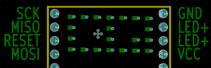
Edit: Just to clarify the pinout. Just don't look too closely at that pin numbering