Author Topic: Home Brew Analog Computer System  (Read 140736 times)

0 Members and 1 Guest are viewing this topic.

Offline GKTopic starter

  • Super Contributor
  • ***
  • Posts: 2607
  • Country: au
Re: Home Brew Analog Computer System
« Reply #200 on: December 14, 2013, 01:19:35 pm »
$55 for a pack of 10 for those shorting bars is a little steep! Element 14 put really ridiculous prices on many things that sell in low volumes.
Bzzzzt. No longer care, over this forum shit.........ZZzzzzzzzzzzzzzzz
 

Offline notsob

  • Frequent Contributor
  • **
  • Posts: 693
  • Country: au
Re: Home Brew Analog Computer System
« Reply #201 on: December 14, 2013, 10:24:45 pm »
Try x-on in perth  http://www.x-on.com.au

their price for pomona 4115's is a little cheaper [ stil f&*^$ing expensive for a bit of plated metal ]
 

Offline GKTopic starter

  • Super Contributor
  • ***
  • Posts: 2607
  • Country: au
Re: Home Brew Analog Computer System
« Reply #202 on: December 15, 2013, 12:52:51 pm »
My very first character, synthesised entirely in analog and discrete logic hardware. Now it's just a matter of constructing the multiplexing and screen RAM addressing/reading logic and finishing the tedious job of the Fourier coefficient character ROM. Then I'll have a 16 character per line by 8 line video text display.
   
« Last Edit: December 15, 2013, 12:55:53 pm by GK »
Bzzzzt. No longer care, over this forum shit.........ZZzzzzzzzzzzzzzzz
 

Offline c4757p

  • Super Contributor
  • ***
  • Posts: 7799
  • Country: us
  • adieu
Re: Home Brew Analog Computer System
« Reply #203 on: December 15, 2013, 01:33:57 pm »
That is some real commitment to this whole "analog" thing. :-+ I'm pretty sure I'd have just done a raster readout. You've executed it very nicely. That looks easily as good as the "perfect" SPICE plots.

And mildly off topic, but the traces all lined up nicely on the beautiful blue screen of your 551 is a work of art by itself.

Damn - the more you make me drool, the more I'm going to want to play around with this myself, and then I won't get anything done! :)
No longer active here - try the IRC channel if you just can't be without me :)
 

Offline Odysseus

  • Regular Contributor
  • *
  • Posts: 147
  • Country: us
Re: Home Brew Analog Computer System
« Reply #204 on: December 15, 2013, 08:54:42 pm »
It's possible to blank a trace in LTSpice by forcing a trace to become "invalid", i.e. by computing the logarithm or square root of a negative value.  However, this only works by doing the math in the waveform viewer, not in an arbitrary source.

An easy way to do this is to generate a blanking signal with a high value of 10V and a low value of -1V (or -anything).  Then in the waveform viewer, multiply your signal of interest by log10(V(blank)).
 

Offline GKTopic starter

  • Super Contributor
  • ***
  • Posts: 2607
  • Country: au
Re: Home Brew Analog Computer System
« Reply #205 on: December 16, 2013, 03:40:48 am »
It's possible to blank a trace in LTSpice by forcing a trace to become "invalid", i.e. by computing the logarithm or square root of a negative value.  However, this only works by doing the math in the waveform viewer, not in an arbitrary source.

An easy way to do this is to generate a blanking signal with a high value of 10V and a low value of -1V (or -anything).  Then in the waveform viewer, multiply your signal of interest by log10(V(blank)).


That's a neat trick. Thanks!


Bzzzzt. No longer care, over this forum shit.........ZZzzzzzzzzzzzzzzz
 

Offline GKTopic starter

  • Super Contributor
  • ***
  • Posts: 2607
  • Country: au
Re: Home Brew Analog Computer System
« Reply #206 on: December 16, 2013, 04:01:16 am »
That is some real commitment to this whole "analog" thing. :-+ I'm pretty sure I'd have just done a raster readout. You've executed it very nicely. That looks easily as good as the "perfect" SPICE plots.

And mildly off topic, but the traces all lined up nicely on the beautiful blue screen of your 551 is a work of art by itself.

Damn - the more you make me drool, the more I'm going to want to play around with this myself, and then I won't get anything done! :)


Compare the pic in my post above to the scope photo. I think I've created the reference sine and cosines with a sufficiently high degree of fidelity.
The five traces on the 551 were produced by a pair of Type 1A1 dual trace plug-ins in the mainframe and a Type CA dual trace plug-in operating externally in a Type 127 preamplifier power supply; all operating in the "alternate" trace switching mode.
I have three 1A1 plug-ins, but one has not yet been restored and has a dodgy channel. That's why I had to resort to using one of my Type CA plug-ins in the Type 127. To operate in "alternate" mode however, the external "trigger" input of the Type 127 needs to be connected to the timebase "+Gate" output pulse provided on the front panel of the oscilloscope, so that the Type CA's trace switching bistable toggles at the end of each sweep.
Unfortunately, however, the Type 127's alternate trigger input is not compatible with the "+Gate" logic thresholds provided by the Type 551 oscilloscope, but it is compatible with the "+Gate" signal levels of my Type 545B oscilloscope. I got around the issue by externally triggering my Type 545B's timebase A from the Type 551's "+Gate" output, so that the timebases of the two oscilloscopes operate in synchronicity, and then triggering the Type CA via the "trigger" provision of the Type 127 from the "+Gate" pulse of the Type 545B.   

You're right about this stuff consuming a great deal of time. I'm going to have to give it a rest now for a few days to attend to other obligations and chores, amongst which are two new babies to look after.............


« Last Edit: December 16, 2013, 07:17:51 am by GK »
Bzzzzt. No longer care, over this forum shit.........ZZzzzzzzzzzzzzzzz
 

Offline GKTopic starter

  • Super Contributor
  • ***
  • Posts: 2607
  • Country: au
Re: Home Brew Analog Computer System
« Reply #207 on: December 21, 2013, 01:09:12 pm »
Haven't expanded the Fourier character ROM to include any character other that 3 at the moment, so regardless of the contents of the display RAM, the only character displayed is a 3.

It's all quite simple, really. The synthesized X and Y deflection waveforms to generate a specific character are traced out during each period of the 20kHz fundamental - so every 50uS. The first and last 12.5% of this period is blanked - this is the Z or intensity modulation for the CRT display.

The 20kHz fundamental clock feeds a 7 stage ripple counter. The first 4 LSB's of the counter feed a 4-bit R-2R DAC, which generates a 16 step staircase waveform that advances on the tracing out of each successive character. This staircase waveform is summed with the synthesized X waveform to generate the complete horizontal deflection signal for the display.
The 3 MSB's of the ripple counter feed a 3-bit R-2R DAC, which consequently generates an 8 step staircase waveform that advances each time the horizontal staircase re-traces back to zero, at the end of a complete line of 16 characters drawn out onto the CRT. The 8 step waveform is inverted and then is summed with the synthesized Y waveform to generate the complete vertical deflection signal for the display. Every advancement of the 8 step waveform thus produces a new line of 16 characters. There are therefore a total of 128 characters displayed, in 8 rows of 16. The full screen is therefore drawn out every 128*50uS = 6.4mS. This gives a refresh rate of 156.25Hz, so there is no perceptible display flicker.

The 7 bits of the ripple counter (Q0 through Q6) also assert the address lines of the screen RAM, while the data output lines of the screen RAM assert the character ROM analog multiplexer, which subsequently selects the character to displayed. There is also provision for the display of blank character spaces by decoding an assigned data value from the screen RAM to assert the blanking signal for the full 50uS character interval.

On top of all of that there is just a little more logic for enabling remote programming of the screen RAM - this includes bus routing and temporary data latches. To program the display, firstly a 7 bit value is placed onto data input lines of the parallel programming port. This value corresponds to the character location on screen to be programmed. An address latch line is then strobed and the data value is placed into the address data latch. A 5-bit data value for the actual character to be displayed is then placed onto the data bus. A character latch line is then strobed and the data value is placed into the character data latch. The control logic then automatically programs the screen RAM from the data values stored in the address and character data latches during the next subsequent blanking interval. This way the screen update is seamless, with no interruption to the display while the screen RAM is being user programmed.

The final version of the display system will also incorporate a "phosphor saver" circuit, with will simply be a pair of non-synchronized, free running ultra low frequency oscillators feeding +/- 10% deflection factors into the horizontal and vertical deflection signals. This will cause the entire display as a block to move/shift around on the CRT face by a small amount at an (at a glance) imperceptibly slow speed, thus saving the phosphor from burn by any static characters, as no character is permanently fixed to the one same position.

I will of course have some prettier/fancier CRT displays to post photos of once I have completed the character ROM.   

« Last Edit: December 21, 2013, 01:33:21 pm by GK »
Bzzzzt. No longer care, over this forum shit.........ZZzzzzzzzzzzzzzzz
 

Offline dannyf

  • Super Contributor
  • ***
  • Posts: 8221
  • Country: 00
Re: Home Brew Analog Computer System
« Reply #208 on: December 21, 2013, 01:31:46 pm »
GK: that's some good stuff. Keep it up!

Quote
Analog Computer System

Sh!!!!!! Please don't tell those folks to whom computers can only be digital.

================================
https://dannyelectronics.wordpress.com/
 

Offline GKTopic starter

  • Super Contributor
  • ***
  • Posts: 2607
  • Country: au
Re: Home Brew Analog Computer System
« Reply #209 on: December 22, 2013, 03:54:16 pm »
GK: that's some good stuff. Keep it up!

Quote
Analog Computer System

Sh!!!!!! Please don't tell those folks to whom computers can only be digital.


Well, despite the usage is was to some degree accepted that the term Analog Computer was a bit of a misnomer. For the pedant, Analog Simulator might be the technically correct, and preferred term.

« Last Edit: December 22, 2013, 03:56:57 pm by GK »
Bzzzzt. No longer care, over this forum shit.........ZZzzzzzzzzzzzzzzz
 

Offline woodchips

  • Frequent Contributor
  • **
  • Posts: 594
  • Country: gb
Re: Home Brew Analog Computer System
« Reply #210 on: December 25, 2013, 09:24:09 pm »
Yes, good stuff, catching up after a period away.

Don't know if you have seen the attached, from a book my Markus, Electronic Circuits.
 

Offline TimNJ

  • Super Contributor
  • ***
  • Posts: 1656
  • Country: us
Re: Home Brew Analog Computer System
« Reply #211 on: December 26, 2013, 04:19:38 am »
I don't have much to input about any of the work you are doing because it is far beyond my scope of understanding, but I have to say, great work! It is really quite inspiring.
 

Offline GKTopic starter

  • Super Contributor
  • ***
  • Posts: 2607
  • Country: au
Re: Home Brew Analog Computer System
« Reply #212 on: January 03, 2014, 02:30:26 pm »
Yes, good stuff, catching up after a period away.

Don't know if you have seen the attached, from a book my Markus, Electronic Circuits.


No, haven't seen that one. The references would be good to follow up.
Bzzzzt. No longer care, over this forum shit.........ZZzzzzzzzzzzzzzzz
 

Offline GKTopic starter

  • Super Contributor
  • ***
  • Posts: 2607
  • Country: au
Re: Home Brew Analog Computer System
« Reply #213 on: January 03, 2014, 03:08:04 pm »
I don't have much to input about any of the work you are doing because it is far beyond my scope of understanding, but I have to say, great work! It is really quite inspiring.


Hey, thanks, no worries.


---------------------------------------------------

Here is the Fourier synthesis character display generator at its current level of completion. There will be 4 boards in total when finished. I have yet to etch and load the Fourier coefficient character ROM board and the sine/cosine filter board. The Sine/Cosine filters are currently (still) assembled on breadboard. There is no complete character ROM at the moment, just, for initial testing/running purposes, a single TL074 op-amp and several coefficient resistors assembled on the breadboard next to the filters to act as a single character ROM for the number 3.
The SOIC chip in the center of the board in the middle, sitting in the air on a piggyback DIP socket, is the SRAM which serves as the user-programmable screen RAM for the generated display. The SOIC is only temporary as I have a DIL-packaged version of the chip still to arrive on back order, which will substitute the SOIC. The part # is CY62256.

 I ended up simplifying the remote programming logic by expanding the data bus to 12 bits. The programming of a specific character on the display is now just a simple matter of placing the 7-bit address value and the 5-bit character code (not ASCII) simultaneously on the 12-bit data bus and then strobing the programming port "write" control pin. This writes the address and character code data values in to a pair of latches (74HCT573) and the control logic automatically writes these to the screen RAM during the subsequent video blanking interval.

Each new character is drawn out on the CRT at 50uS intervals, 12.5uS of which is a blanking interval during which the CRT beam is cut-off. During this 12.5uS blanking interval the "write" control input to the programming port is disabled so that the latches cannot interrupted, and the screen RAM is written with the data stored in the larches. All this means that the screen RAM is programmed and updated without any interruption to the visible display.

However because the programming port is disabled during each 12.5uS blanking interval, and remote programming is completely asynchronous, the "write" control input of the remote programming port must be strobed for absolute minimum of 12.5uS plus a setup and hold time adequate for the latches to receive and store their data. So long as this simple requirement is met, the latches will be reliably written even if the rising edge of a "write" strobe on the programming port is time coincident with the very start of a blanking interval. This was about the simplest manner in which I could implement the remote programming logic.

All inputs to the remote programming port are TTL level compatible. Despite needing voltage level translation, the simple 12-bit port will make the display unit also directly compatible with the PDP8 work-alike digital computer project that I intend to start on once this analog computer is completed and out of the way.   

The other assembled PCB contains the analog circuitry for generating the deflection circuitry. This includes a 2-channel by 16-way analog multiplexer, addressed by the data port of the screen RAM, which serves as the ROM multiplexer to select the character to displayed at any given position on the screen. The inputs to the multiplexer are currently not wired as I haven't assembled the ROM board yet. At the moment the only character that can be displayed is either a 3 or a blank space (as shown in the picture on on the scope CRT).

Dunno if all that babble makes the operation of the whole thing generally clear or not.
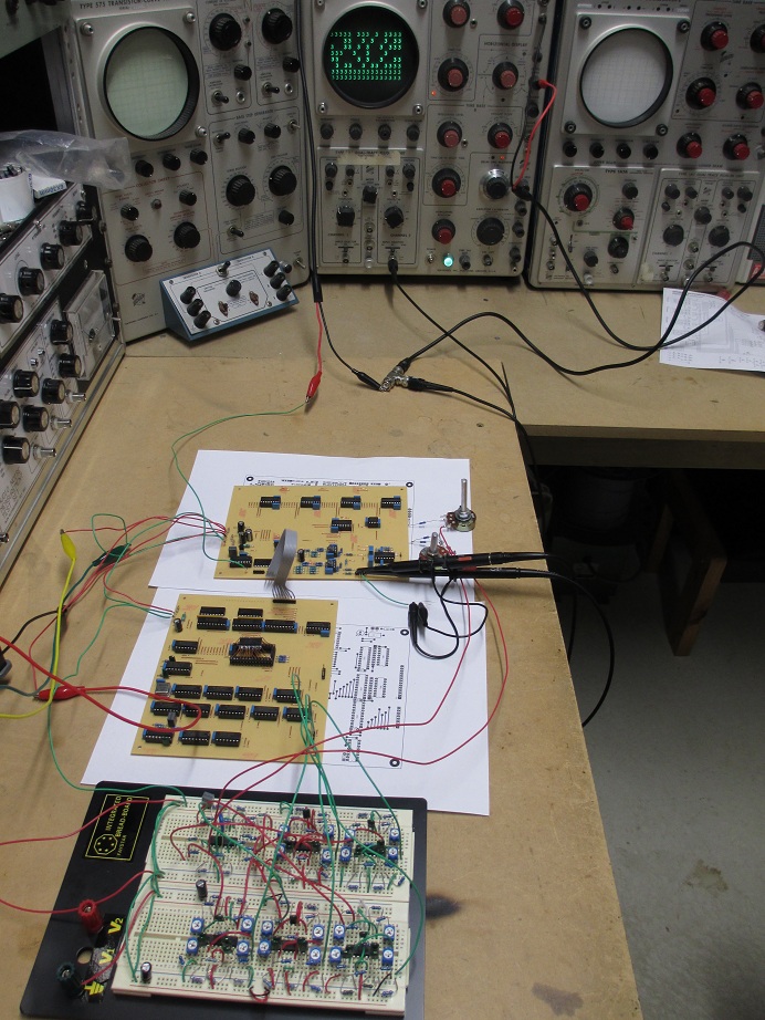


« Last Edit: January 03, 2014, 03:27:28 pm by GK »
Bzzzzt. No longer care, over this forum shit.........ZZzzzzzzzzzzzzzzz
 

Offline GKTopic starter

  • Super Contributor
  • ***
  • Posts: 2607
  • Country: au
Re: Home Brew Analog Computer System
« Reply #214 on: January 04, 2014, 03:13:33 am »
A pair of potentiometers permits the character X and Y sizes to be individually adjusted to user preference.....


I've also attached a PDF of the deflection board schematic. This board combines all of the analogue signals as necessary to produce the X and Y deflection and intensity (Z) signals for the oscilloscope. The 7 address lines from the screen memory on the digital board are decoded on the deflection board by a pair of R-2R DACs (4-bit for the horizontal and 3-bit for the vertical channel) which produce the X and Y step waveforms generating the 16 column by 8 row character grid.

The whole generated display as a block constantly moves around on the screen visually randomly, but very slowly, approx +/-5% on both the X and Y axes. This is the CRT "phosphor saver" function. These deflection factors are produced by the pair of non-synchronized, ultra low frequency triangle wave oscillators based on IC U9A through U9D.


« Last Edit: January 04, 2014, 10:18:11 am by GK »
Bzzzzt. No longer care, over this forum shit.........ZZzzzzzzzzzzzzzzz
 

Offline GKTopic starter

  • Super Contributor
  • ***
  • Posts: 2607
  • Country: au
Re: Home Brew Analog Computer System
« Reply #215 on: January 12, 2014, 03:15:16 am »
In a marathon sitting, with the aid of several sheets of graph paper and pen, a ruler and some string (to measure the lengths of my hand drawn closed-function curves in order to properly proportion the blanked to un-blanked portions) and Jahonen's discrete Fourier transform, I have finally worked out the the sine and cosine Fourier coefficient values for my entire character set. Now it is is just a matter of loading the analog character ROM board, and the display unit will be finished. Although hexadecimal values are usually written with uppercase letters, the more complex uppercase letters (A through F) were too difficult to trace out with a single closed function curve, so I had to settle for lower case.

Instead of visiting the forum from now on I'll be devoting my time to updating my so far largely neglected website instead. Further updated will be posted at www.glensstuff.com


Bzzzzt. No longer care, over this forum shit.........ZZzzzzzzzzzzzzzzz
 

Offline GKTopic starter

  • Super Contributor
  • ***
  • Posts: 2607
  • Country: au
Re: Home Brew Analog Computer System
« Reply #216 on: January 26, 2014, 05:45:35 am »
Just finished the webpage write up for the 3-D projective unit:

http://www.glensstuff.com/3dpu/3dpu.htm

Has links to all of the design files... Gerbers / uC Hex, etc.
Bzzzzt. No longer care, over this forum shit.........ZZzzzzzzzzzzzzzzz
 

Offline C

  • Super Contributor
  • ***
  • Posts: 1346
  • Country: us
Re: Home Brew Analog Computer System
« Reply #217 on: January 26, 2014, 08:10:46 am »
Looks like your having fun.

For you trick bag
You may not have seen this, Instead of using X and Y like a normal scope some old equipment used a circle for the trace with time being the rotation on the circle and what would be the vertical scope channel being a movement in radius. The advantage was the long trace compared to normal X & Y display. While it sounds hard to use, it was actually very easy. Using the beam to put up what would be grid lines was also quick.

Could be fun to play with

C       
 

Offline GKTopic starter

  • Super Contributor
  • ***
  • Posts: 2607
  • Country: au
Re: Home Brew Analog Computer System
« Reply #218 on: January 28, 2014, 07:58:02 am »
Your description vaguely reminds me of some time standard/chronograph synchronizers. Do you recall a model number or make of scope that displayed that way?
 
Bzzzzt. No longer care, over this forum shit.........ZZzzzzzzzzzzzzzzz
 

Offline chickenHeadKnob

  • Super Contributor
  • ***
  • Posts: 1055
  • Country: ca
Re: Home Brew Analog Computer System
« Reply #219 on: January 28, 2014, 08:45:56 am »
I thought C was describing polar coordinates, no?
 

Offline GKTopic starter

  • Super Contributor
  • ***
  • Posts: 2607
  • Country: au
Re: Home Brew Analog Computer System
« Reply #220 on: January 28, 2014, 10:20:17 am »
One of the synchronizer scopes I have in mind used polar coordinates of sorts to indicate the beat between a ref. frequency and a signal input.

My 3-D projective unit could be used to produce spherical polar coordinate displays.  It would just be a simple matter of first transforming the spherical polar coordinates to Cartesian ones:

http://keisan.casio.com/exec/system/1359534351

I could build a separate unit for doing that, or I could just patch a computer program to do it (summers combined with sin/cos function generators and 4-quadrant multipliers). The former would be more practical in use of course, which is why I have gone through the trouble of constructing the current projective unit. Could be an interesting project.................

 
« Last Edit: January 28, 2014, 12:26:00 pm by GK »
Bzzzzt. No longer care, over this forum shit.........ZZzzzzzzzzzzzzzzz
 

Offline GKTopic starter

  • Super Contributor
  • ***
  • Posts: 2607
  • Country: au
Re: Home Brew Analog Computer System
« Reply #221 on: January 28, 2014, 11:47:08 am »
Come to think of it a 2-dimensional polar coordinate oscilloscope, where time is the independent variable, represented by the angle of rotation about the pole, would be a rather simple thing to make.

Firstly, you'd need to design a triggered timebase that produces a "sweep" consisting of a single cycle of a sine-wave, rather than a ramp voltage. From this an all-pass filter could then be used to generate the cosine "sweep" term. Simply multiply these two signals independently with the uni-polar signal input voltage representing the distance from the pole and you have your X and Y deflection signals respectively.   
« Last Edit: January 28, 2014, 11:50:48 am by GK »
Bzzzzt. No longer care, over this forum shit.........ZZzzzzzzzzzzzzzzz
 

Offline GKTopic starter

  • Super Contributor
  • ***
  • Posts: 2607
  • Country: au
Re: Home Brew Analog Computer System
« Reply #222 on: January 29, 2014, 12:01:00 pm »
Although my priority right now is to complete the construction of my Fourier synthesis display unit and write it up on my website, it seems I just can't help myself. This evening I got half way to having a functional polar coordinate oscilloscope. I knocked up a quick and dirty triggered timebase generator which produces sin and cos sweep terms, for time as the independent variable represented by rotation about the pole:


The top waveform is the trigger pulse and the lower two waveforms are the subsequent (rising-edge triggered) sin and cos "sweeps". The slopes/breakpoints haven't been calibrated yet and I still have to breadboard the shaping circuit(s) that will transform these triangular waveforms into smooth sine and cosine curves. I will probably use BJT long-tail pair shapers. However that will have to wait for another spare evening.

In the meanwhile, here is a very quick play in SPICE, of sine, sawtooth and square waves displayed in polar coordinates:

« Last Edit: January 29, 2014, 12:08:19 pm by GK »
Bzzzzt. No longer care, over this forum shit.........ZZzzzzzzzzzzzzzzz
 

Offline GKTopic starter

  • Super Contributor
  • ***
  • Posts: 2607
  • Country: au
Re: Home Brew Analog Computer System
« Reply #223 on: January 30, 2014, 11:21:16 am »
You say polar coordinate oscilloscope, I make polar coordinate oscilloscope (in 2 free evenings  ;D ).

As I had to use parts that I had at immediately at hand the bread-boarded prototype circuitry is still very crude and there is still plenty of scope for improving the phase and amplitude linearity of the generated displays. For shaping the sine and cosine "sweeps" for the angular deflection I used logarithmic shapers that exploit the non-linearity of a BJT long-tail transistor pair. I am not overall happy with this approach. No matter how the circuit constants are tweaked, the lowest THD null always results in a sine function with excessively pointy nipples (well that is what they look like to me). This non linearity is quite visible when plotting the circumference of a circle on the CRT. However there are other (better) ways to do that job. I'm also using quite crappy and obsolete (EXAR) multiplier chips that had to be compensated down for breadboard stability to the extent that phase distortion in the display is not insignificant at even modest operating frequencies. However the fundamentals are covered/proven and now it's just matter of refining the design. I intend to make an instrument with a full oscilloscope-like front-end, with comprehensive timebase, triggering, radial (rather than "vertical") input sensitivity and offset controls - though this will go on the back burner for the time being while I get back to finishing some other stuff.
     

« Last Edit: January 30, 2014, 11:24:09 am by GK »
Bzzzzt. No longer care, over this forum shit.........ZZzzzzzzzzzzzzzzz
 

Offline GKTopic starter

  • Super Contributor
  • ***
  • Posts: 2607
  • Country: au
Re: Home Brew Analog Computer System
« Reply #224 on: January 30, 2014, 01:03:36 pm »
For shaping the sine and cosine "sweeps" for the angular deflection I used logarithmic shapers that exploit the non-linearity of a BJT long-tail transistor pair. I am not overall happy with this approach. No matter how the circuit constants are tweaked, the lowest THD null always results in a sine function with excessively pointy nipples (well that is what they look like to me). This non linearity is quite visible when plotting the circumference of a circle on the CRT. However there are other (better) ways to do that job.


The squaring technique using a 4-quadrant multiplier (X & Y inputs connected together) looks like the most viable alternative right now........ Mathematically perfect sine curves..............

Bzzzzt. No longer care, over this forum shit.........ZZzzzzzzzzzzzzzzz


Share me

Digg  Facebook  SlashDot  Delicious  Technorati  Twitter  Google  Yahoo
Smf