Author Topic: Home Brew Analog Computer System  (Read 140989 times)

0 Members and 1 Guest are viewing this topic.

Offline robrenz

  • Super Contributor
  • ***
  • Posts: 3035
  • Country: us
  • Real Machinist, Wannabe EE
Re: Home Brew Analog Computer System
« Reply #225 on: January 30, 2014, 01:08:54 pm »
I am still following GK, great stuff :-+

Offline c4757p

  • Super Contributor
  • ***
  • Posts: 7799
  • Country: us
  • adieu
Re: Home Brew Analog Computer System
« Reply #226 on: January 30, 2014, 01:24:46 pm »
Me too!

But mathematically perfect sine? What am I missing? Looks parabolic to me.
No longer active here - try the IRC channel if you just can't be without me :)
 

Offline GKTopic starter

  • Super Contributor
  • ***
  • Posts: 2607
  • Country: au
Re: Home Brew Analog Computer System
« Reply #227 on: January 30, 2014, 10:41:17 pm »
Quote from: c4757p link=topic=12331.msg378294#msg378294
  What am I missing? Looks parabolic to me.


Nothing at all; I just shouldn't post after midnight on a workday, lol.
Yes, it is of course parabolic and that (sin/cos terms) results in a circle which is more like a square with broadly rounded corners. That rules it out, along with the logarithmic shaper.

I guess I'm left with breakpoint-shaping.
 
« Last Edit: January 30, 2014, 10:45:13 pm by GK »
Bzzzzt. No longer care, over this forum shit.........ZZzzzzzzzzzzzzzzz
 

Offline C

  • Super Contributor
  • ***
  • Posts: 1346
  • Country: us
Re: Home Brew Analog Computer System
« Reply #228 on: January 31, 2014, 06:03:19 am »
Hi

Are you making creating a time base circle too hard?
Look at the video of dave cal of the time base.
Just create a Sine wave for your time base, one cycle equal one sweep.
The default amplitude of which is the circle size.
Do a second Sine wave with 90 degree phase delay or add a 90 degree phase delay to the first.
You have your X an Y base.
Great timebase with no retrace time.
Think what would be the vert on scope is the input to two voltage-controlled amplifiers with the gain controlled by the X & Y above.


http://www.google.com/patents/US3047767
here is a quick find, real new stuff (1932)

Have you seen a radar scope.
Great for knowing what is around you but not real great for telling the direction. If you start at the outside edge with greater distance to the center, easer to read direction while harder to get the great picture understanding. 

One use I recall the time base was the circle close to the outer edge of the tube with vert of normal scope being a radial deflection to or past the center of tube. 

Some had a huge display with very long persistence.
I do remember that when used the circle display was much better then normal scope display.

Radio direction finding was one use.
Think I remember something about radio signal analyst.
Been to long for a lot of details, sorry.

Think the big selling points was the very long trace with no retrace time.

C
 

Offline GKTopic starter

  • Super Contributor
  • ***
  • Posts: 2607
  • Country: au
Re: Home Brew Analog Computer System
« Reply #229 on: January 31, 2014, 07:38:35 am »
Hi

Are you making creating a time base circle too hard?
Look at the video of dave cal of the time base.
Just create a Sine wave for your time base, one cycle equal one sweep.
The default amplitude of which is the circle size.
Do a second Sine wave with 90 degree phase delay or add a 90 degree phase delay to the first.
You have your X an Y base.


Sure, but that wouldn't be a true triggered timebase. What you describe is exactly what I did for my Fourier synthesis character generator, but that is an entirely different application.

A true triggered time base is important as you want the "sweep" synchronized with the input signal, just like in any other scope. 

If I wanted to do it the simplest way possible, I would just make an injection-locked state variable (quadrature) oscillator. However that would have major  functional limitations - the timebase sweep time (and amplitude!) could not be calibrated and synchronization could only be had with input signals that are frequency multiples of the timebase oscillation frequency.


« Last Edit: January 31, 2014, 07:41:17 am by GK »
Bzzzzt. No longer care, over this forum shit.........ZZzzzzzzzzzzzzzzz
 

Offline C

  • Super Contributor
  • ***
  • Posts: 1346
  • Country: us
Re: Home Brew Analog Computer System
« Reply #230 on: January 31, 2014, 06:46:13 pm »

you just need the electronic version of a  mechanical clutch.
On trigger you drop the clutch connecting the input (the X & Y signals) to the Output X & Y signals that was set to start with the desired starting reference..

I think Selsyn and Synchro Devices were some of the first IO devices of an Analog Computer
http://en.wikipedia.org/wiki/Synchro

Think of what a Sine wave really is, the result of having a marker attached to rim of a rolling circle when the rim is rolling on a line.
If you are thinking the circle has a shaft then rules have to change for that way of thinking.

I think I remember from a very short crash course on Selsyn's that there is a circuit that will do what you want. One of the first uses of a CRT was as an improvement from using Selsyns. So in the dust of time is probably the circuit with a good description.

Note that what you create for circuits today could be much more complicated due to not using something very common in old days.
A simple OP amp is shown as two variable resistors connecting the two supplies to a common output. In the old days it was not unusual to have resistors added to the supply leads of the output variable resistors.
By adding the two resistors, a single ended center input Op Amp could convert to a differential output from the power rails. Need more signal swing, connect the outputs of two Op Amps together with only one having the two to-rail resistors.

It was also not uncommon to have output of one or more Op Amps supplying the rail voltage to another Op Amp.

Some things you do not see much of these days

C
 

Offline robrenz

  • Super Contributor
  • ***
  • Posts: 3035
  • Country: us
  • Real Machinist, Wannabe EE
Re: Home Brew Analog Computer System
« Reply #231 on: January 31, 2014, 07:28:16 pm »
Think of what a Sine wave really is, the result of having a marker attached to rim of a rolling circle when the rim is rolling on a line.

C

That would be a Cycloid not a sine wave.
http://en.wikipedia.org/wiki/Cycloid

Offline C

  • Super Contributor
  • ***
  • Posts: 1346
  • Country: us
Re: Home Brew Analog Computer System
« Reply #232 on: January 31, 2014, 09:43:39 pm »
Think of what a Sine wave really is, the result of having a marker attached to rim of a rolling circle when the rim is rolling on a line.

C

That would be a Cycloid not a sine wave.
http://en.wikipedia.org/wiki/Cycloid
Yes,
 forgot the connecting rod.
or the slide slot.

C
 

Offline GKTopic starter

  • Super Contributor
  • ***
  • Posts: 2607
  • Country: au
Re: Home Brew Analog Computer System
« Reply #233 on: January 31, 2014, 11:39:23 pm »

you just need the electronic version of a  mechanical clutch.
On trigger you drop the clutch connecting the input (the X & Y signals) to the Output X & Y signals that was set to start with the desired starting reference..


I'm afraid it is not that simple. What you describe provides no mechanism for synchronizing the zero crossing of a free running sinusoidal timebase (oscillator) with the trigger pick-off threshold/point of a periodic input signal.

BTW, there is only one input signal (neither X nor Y) - that representing the distance from the pole, r.

Perhaps this simplified block diagram of the prototype circuit will make things clearer:


Polar coordinate system explained here:
http://en.wikipedia.org/wiki/Polar_coordinate_system


« Last Edit: February 01, 2014, 12:03:05 am by GK »
Bzzzzt. No longer care, over this forum shit.........ZZzzzzzzzzzzzzzzz
 

Offline johnwa

  • Frequent Contributor
  • **
  • Posts: 255
  • Country: au
    • loopgain.net - a few of my projects
Re: Home Brew Analog Computer System
« Reply #234 on: February 03, 2014, 09:41:50 am »

I'm afraid it is not that simple. What you describe provides no mechanism for synchronizing the zero crossing of a free running sinusoidal timebase (oscillator) with the trigger pick-off threshold/point of a periodic input signal.

BTW, there is only one input signal (neither X nor Y) - that representing the distance from the pole, r.

Perhaps this simplified block diagram of the prototype circuit will make things clearer:
 

Hi GK,

It is nice to see some more analogue computation ideas on the go! One of the things on my to-do list at the moment is a phasor display for working with polyphase systems. I am thinking that I will generate some quadrature sine waves, then multiply with the incoming signals and low pass filter to get the endpoints. A further multiplication with a ramp will give the lines for the phasors.

This is a somewhat similar situation to your current problem, though I was going to have my oscillator phase locked to one of the incoming signals, but otherwise free running.

One thought occurred to me - would it be possible to 'freeze' the state of a quadrature sinewave oscillator using some sort of sample and hold? It could then be set up to a known phase angle, then triggered by the input signal. I haven't really though through the details of this, but it might possibly be worth investigating.
 

Offline GKTopic starter

  • Super Contributor
  • ***
  • Posts: 2607
  • Country: au
Re: Home Brew Analog Computer System
« Reply #235 on: February 03, 2014, 12:41:01 pm »
Hi GK,

It is nice to see some more analogue computation ideas on the go! One of the things on my to-do list at the moment is a phasor display for working with polyphase systems. I am thinking that I will generate some quadrature sine waves, then multiply with the incoming signals and low pass filter to get the endpoints. A further multiplication with a ramp will give the lines for the phasors.

This is a somewhat similar situation to your current problem, though I was going to have my oscillator phase locked to one of the incoming signals, but otherwise free running.

One thought occurred to me - would it be possible to 'freeze' the state of a quadrature sinewave oscillator using some sort of sample and hold? It could then be set up to a known phase angle, then triggered by the input signal. I haven't really though through the details of this, but it might possibly be worth investigating.


Hi John, that sounds like an interesting project. I have since gone back to pondering the differential equations that describe the desired waveforms and I am proud to say that I have come up with an extremely simple circuit that solves the problem of generating triggered, single cycle complementary sine and cosine waveforms of very high fidelity - simply by going back to good old analog computing fundamentals.

Here is the fundamental circuit:


All there is to it is two integrator stages with initial conditions in a feedback loop with an inverter. Consider the circuit in the initial condition mode: Integrator 1 is steady/idle at 10V output while integrator 2 is steady/idle at 0V output. Now imagine the initial condition switches open (the "initial_condition" control line goes low). Integrator 2 will begin integrating the 10V potential from the output of integrator 1, its output, beginning at 0V, starting on a downwards trajectory. The output of integrator 2 is inverted by the third op-amp stage in the loop and fed back to integrator 1, which responds by integrating the inverted output of integrator 2. The result is a pair of sine and cosine waveforms from the output of the inverting stage and the output of integrator 1 respectively - it really is that simple!

Of course my real world implementation does not use a floating voltage source to set the IC of integrator 1 and there is some simple control logic involved, but I'll be able to share that with you another evening - got to go to bed now, unfortunately. I think this is probably close to what you were contemplating in your "sample and hold" idea?


EDIT:I have attached the LTspice file. Just rename it from *.asc.txt to *.asc (*.asc files not permitted by the forum software).
 
« Last Edit: February 03, 2014, 12:49:44 pm by GK »
Bzzzzt. No longer care, over this forum shit.........ZZzzzzzzzzzzzzzzz
 

Offline c4757p

  • Super Contributor
  • ***
  • Posts: 7799
  • Country: us
  • adieu
Re: Home Brew Analog Computer System
« Reply #236 on: February 03, 2014, 12:46:11 pm »
Oh, that is nice. :-+
No longer active here - try the IRC channel if you just can't be without me :)
 

Offline c4757p

  • Super Contributor
  • ***
  • Posts: 7799
  • Country: us
  • adieu
Re: Home Brew Analog Computer System
« Reply #237 on: February 03, 2014, 06:06:45 pm »
There's my first attempt at a practical circuit. Unfortunately I don't have the time right now to breadboard it :(
No longer active here - try the IRC channel if you just can't be without me :)
 

Offline GKTopic starter

  • Super Contributor
  • ***
  • Posts: 2607
  • Country: au
Re: Home Brew Analog Computer System
« Reply #238 on: February 04, 2014, 12:10:44 am »
There's my first attempt at a practical circuit. Unfortunately I don't have the time right now to breadboard it :(


Now you just need a direction sensitive threshold comparator and some logic to terminate the "sweep" by reinstating initial conditions at the completion of the first cycle - to await the next sweep triggering pulse.

 
Bzzzzt. No longer care, over this forum shit.........ZZzzzzzzzzzzzzzzz
 

Offline GKTopic starter

  • Super Contributor
  • ***
  • Posts: 2607
  • Country: au
Re: Home Brew Analog Computer System
« Reply #239 on: February 04, 2014, 08:48:29 am »
Here is a pretty complete simulation of the polar-coordinate oscilloscope timebase that I have developed:
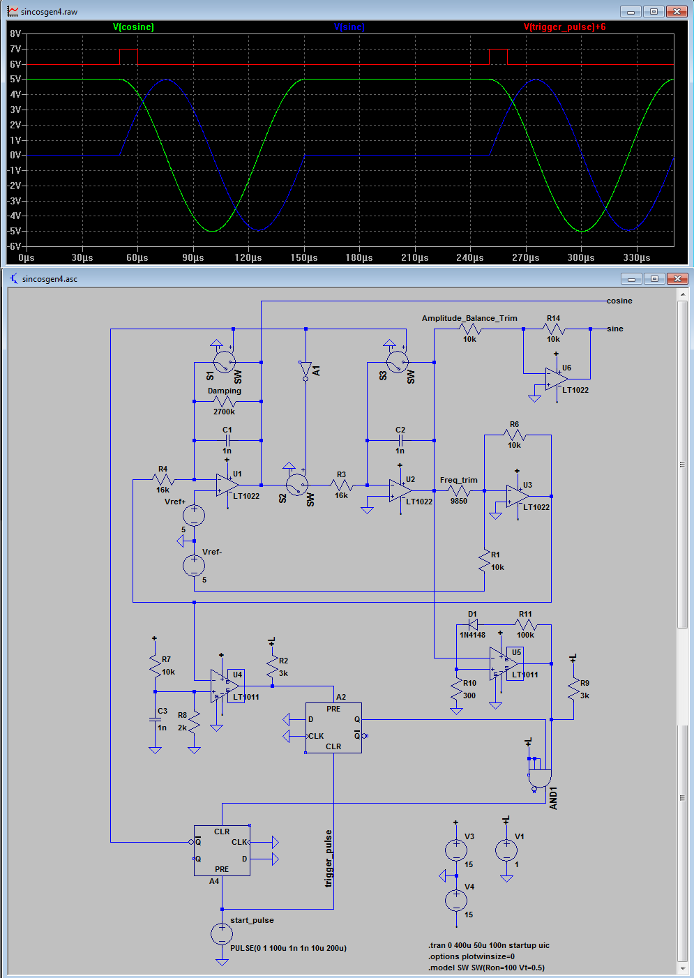


Some brief notes:

Assuming equal R and C values for the two integrators and a unity gain inverting stage, the frequency of oscillation is equal to 1/2piRC.
Oscillation happens at the frequency at which the gain around the loop is equal to 1. The operating frequency can therefore be trimmed by tweaking the gain
of the inverting stage only. However this will result in a small amplitude imbalance between the sine and cosine waveforms (however they will always be in "perfect quadrature". This needs to the trimmed separately and externally, in an stage outside of the feedback loop.

Another thing that will cause an amplitude imbalance between the sin and cos waveforms is a C and/or R variation between the two integrator stages. I use 0.1% resistors for R so the greatest/actually significant source of error is in the capacitor tolerances. The resultant amplitude imbalance is directly proportional to the capacitor value imbalance.

In my timebase, I switch decade ranges by switching different value timing caps. There are 3 decade ranges. The range switch is a 4-pole 3-position rotary. Two of the poles are used to switch the integrator capacitors. The third pole is use to switch one of three gain-adjusting trimpots in the inverting stage feedback so that the operating frequency ("sweep" period) can be accurately trimmed for each range. Finally, the 4th and final pole of the range-selecting rotary switch is used to select one of another three trimpots that accurately trim the amplitude balance between the sin and cos waveforms for each range.

I implemented the initial condition setting in a manner that results in no amplitude glitching of the desired signals. Analog switches are used to short the integrator capacitors and a +5V initial condition for the cosine integrator is achieved by elevating the virtual earth of the integrator to +5V with a precision reference. Note that I have used an additional analog switch to disconnect (when initial conditions are forced) the summing junction of the integrator from which the sinewave is derived. This prevents the current that would otherwise be forced into this integrators summing junction by the +5V initial condition of the preceding (cosine) integrator stage from developing an DC offset error at the output of this integrator due to the non-zero on-state resistance of the analog switch shorting the integration capacitor.

The circuit can be likened to a simplified state-variable oscillator without the damping feedback and amplitude servo control. In theory, with ideal integrator stages, the circuit would oscillate indefinitely at a constant amplitude as initially defined by the initial conditions. However due to the finite gain-bandwidth product of real op-amps as used for the integrator stages, in this particular circuit, the Q-multiplication effect will always result in amplitude growth with time.
If allowed to oscillate for enough number of cycles, the amplitudes of the sin and cos terms will eventually grow until the amplifiers clip and they become square waves.
While this isn't an issue in the design here as only the first cycle of oscillation from the initial conditions is used for the oscilloscope sweep before initial conditions are reinstated, at higher operating frequencies I have found the amplitude growth over just one cycle to be significant (in the order of 0.5-1% at 10kHz). When potting a circle on the oscilloscope using these sin and cos terms, this results in the end point not meeting up exactly correctly with the start point.
However there is a simple fix to the problem. Trim-able negative damping (to precisely counter the amount positive damping due to Q-multiplication) can be applied with the simple inclusion of a high value trimmer resistor in parallel with the capacitor of the integrator from which the cosine term is derived only. This resistor is the one labeled "damping" in my simulation schematic.

In each range, I switch frequencies in three 1/2/5 steps, by switching fixed 0.1% tolerance R's for the integrators (16k, 32k and 80k). This requires and other rotary switch - 2 poles, 3-positions. There is therefore a total of 9 (3x3) calibrated timebase frequencies (50mS to 100uS). Switched integrator capacitors are 1, 10 and 100nF.
 
I have attached the LTspice simulation file (renamed *.txt once again). It includes a simplified logic simulation of the comparator an digital elements required to automatically detect the end of one complete "sweep" cycle and re-instate initial conditions in idle mode, until the next sweep trigger input pulse occurs. 

So there you have it; that should be everything that you need to know to implement a timebase for your experimental polar-coordinate or phasor-display oscilloscope.  ;D

EDIT:
I have noticed one small error/infelicity in the simulation. For the hysteresis of zero-crossing detector/comparator U5 to work correctly (so that in real life the detector does not oscillate away while the sine term is maintained in the initial condition mode (0V) ), the open-collector pullup resistor R9 will be tied to +15V rather than +1V. 1V is used in the sim for the logic high level as this is the default in LTspice for the "special function" digital logic elements. 
« Last Edit: February 04, 2014, 10:11:06 am by GK »
Bzzzzt. No longer care, over this forum shit.........ZZzzzzzzzzzzzzzzz
 

Offline johnwa

  • Frequent Contributor
  • **
  • Posts: 255
  • Country: au
    • loopgain.net - a few of my projects
Re: Home Brew Analog Computer System
« Reply #240 on: February 04, 2014, 11:10:10 am »

Of course my real world implementation does not use a floating voltage source to set the IC of integrator 1 and there is some simple control logic involved, but I'll be able to share that with you another evening - got to go to bed now, unfortunately. I think this is probably close to what you were contemplating in your "sample and hold" idea?


Yes, this was basically what I was thinking of, though I hadn't worked out the details. I might give your circuit a go for my application, when I eventually get round to looking at it.

I have ordered a load of LM13700 OTAs for this project, primarily for use as multipliers (I would have liked to use AD833s, but they are $$$  :( ) Though I think they can be used in an oscillator configuration that will give simple frequency control and amplitude stabilization, without problems with matching the phases.  (I will also want a three phase oscillator at some point). I will see what I can come up with when they get here.
 

Offline GKTopic starter

  • Super Contributor
  • ***
  • Posts: 2607
  • Country: au
Re: Home Brew Analog Computer System
« Reply #241 on: February 04, 2014, 11:41:19 am »
A quick e-bay search came up with this:

http://www.ebay.com/itm/10pcs-XR2208CP-XR2208-DIP-16-EXAR-/180915775470

Not my favorite multiplier IC, but that's pretty cheap at 10 devices for around about the price of a pair of AD633's. They are NOS, being long obsolete now, but fine for experimenting with. Might be worth a punt.

Datasheet attached.
 
Bzzzzt. No longer care, over this forum shit.........ZZzzzzzzzzzzzzzzz
 

Offline mikejp56

  • Contributor
  • Posts: 13
Re: Home Brew Analog Computer System
« Reply #242 on: February 09, 2014, 10:23:48 pm »
Hi GK,
I started an analog computer project about 2 years ago, but it wasn't nearly as ambitious as yours.
After much research I decided on 4 integrators, 4 summing amps, 4 inverters, and 2 4 quadrant multipliers. I also decided to use 8 potentiometers for coefficients, +/- 1V reference supplies, and a zero center analog meter for output.
This system will use a handful of op amp ICs and logic ICs for switching, and several 4066 quad analog switches to actually do the switching.
I had started to build it, but then life intervened and I put it aside for 2 years. I have since resurrected it, and read your posts with great interest.
I wish you luck with your design, and when mine is finished and running, I will post the schematics and a writeup.
Regards,
Mike
 

Offline GKTopic starter

  • Super Contributor
  • ***
  • Posts: 2607
  • Country: au
Re: Home Brew Analog Computer System
« Reply #243 on: February 10, 2014, 12:48:09 am »
Hi Mike,

Sounds good; will be interesting to see.
Bzzzzt. No longer care, over this forum shit.........ZZzzzzzzzzzzzzzzz
 

Online IanB

  • Super Contributor
  • ***
  • Posts: 11880
  • Country: us
Re: Home Brew Analog Computer System
« Reply #244 on: February 10, 2014, 01:18:13 am »
All there is to it is two integrator stages with initial conditions in a feedback loop with an inverter.

This is fundamentally neat and elegant. You have a circuit that solves the following differential equations:

y = Tc dx/dt
x = -Tc dy/dt

Set x = sin(t/Tc), then y = Tc d[sin(t/Tc)]/dt = cos(t/Tc)
and x = - Tc d[cos(t/Tc)]/dt = sin(t/Tc)

However, I think in practice an automatic gain control circuit is required to keep the amplitude constant, otherwise any small errors in the system will be integrated without limit.
 

Offline c4757p

  • Super Contributor
  • ***
  • Posts: 7799
  • Country: us
  • adieu
Re: Home Brew Analog Computer System
« Reply #245 on: February 10, 2014, 01:21:51 am »
However, I think in practice an automatic gain control circuit is required to keep the amplitude constant, otherwise any small errors in the system will be integrated without limit.

The beauty, though, is that it's only allowed to "oscillate" for one cycle.
No longer active here - try the IRC channel if you just can't be without me :)
 

Offline GKTopic starter

  • Super Contributor
  • ***
  • Posts: 2607
  • Country: au
Re: Home Brew Analog Computer System
« Reply #246 on: February 12, 2014, 11:12:09 pm »
Yes, a single cycle before initial conditions are reinstated; but see my subsequent comments on damping.

If an amplitude servo is added to facilitate continuous oscillation, you'll wind up with what is known as a State Variable Oscillator, such as this:

http://www.users.on.net/~glenk/thd/generator.pdf
Bzzzzt. No longer care, over this forum shit.........ZZzzzzzzzzzzzzzzz
 

Offline GKTopic starter

  • Super Contributor
  • ***
  • Posts: 2607
  • Country: au
Re: Home Brew Analog Computer System
« Reply #247 on: March 17, 2014, 11:19:47 am »
I finally have a completed sin/cos, triggered timebase up and running using the above described method. Has 12 calibrated sweep speeds in 4 ranges, from 0.5s to 100uS in 1/2/5 steps. Other features included are an auto-triggering mode and user-variable trigger hold-off. I'm still tweaking a few component values and finalizing the schematic.
Bzzzzt. No longer care, over this forum shit.........ZZzzzzzzzzzzzzzzz
 

Offline GKTopic starter

  • Super Contributor
  • ***
  • Posts: 2607
  • Country: au
Re: Home Brew Analog Computer System
« Reply #248 on: April 29, 2014, 01:50:03 pm »
Things have been a little hectic for me lately, but this evening I finally managed to get the (almost complete) Fourier synthesis character generator/display unit up and running.

Here are the four main boards wired up:


Here is a closeup of the actual analog Fourier ROM for the 16 character character set (0-through-f). The IC's are all TL074 quad op-amps. The ROM is just a resistor matrix, the Fourier components simply being passively summed to produce the necessary X and Y deflection waveforms to trace out each unique character onto the CRT. Soldering in all of those resistors was about two or three orders of magnitude less tedious than actually computing the values.


When initially powered a random garble of characters appears on screen, depending on how the un-programmed screen RAM comes up:


For initial testing purposes, I wired a series for switches to the 12-bit parallel programming port, to manually program the display. The seven switches to the left are the address lines, selecting the actual character to be programmed, while the 5 remaining switches are the data lines. There are 17 characters if the blank space is counted. This is why I required 5 bits for the data port rather than 4. The (micro) push button to the far right is the strobe line. When pressed the address and data line status is written to the internal latches and seamlessly transferred to the screen RAM during the next subsequent blanking interval, updating the display.


Here is the display I initial generated playing with the switches. I numbered the columns (16) and rows ( 8 ) and left some of the random stuff in the middle.

« Last Edit: April 29, 2014, 01:58:43 pm by GK »
Bzzzzt. No longer care, over this forum shit.........ZZzzzzzzzzzzzzzzz
 

Offline dr_dan

  • Contributor
  • Posts: 28
  • Country: gb
Re: Home Brew Analog Computer System
« Reply #249 on: April 29, 2014, 01:55:31 pm »
Beautiful!  :clap:

Been waiting for this, since you posted a screenshot of "3" some while back!


Share me

Digg  Facebook  SlashDot  Delicious  Technorati  Twitter  Google  Yahoo
Smf