Author Topic: Home Brew Analog Computer System  (Read 140730 times)

0 Members and 1 Guest are viewing this topic.

Offline SeanB

  • Super Contributor
  • ***
  • Posts: 16276
  • Country: za
Re: Home Brew Analog Computer System
« Reply #75 on: April 10, 2013, 06:38:22 pm »
With the CRT you are using did you connect up the degaussing coil ***EXACTLY*** as it was in the set originally, along with connecting it up to power to operate when on the bench in the position it is in. Certain tubes are incredibly sensitive to stray fields, and this often will affect only the gun nearest to the source, or where the change is greatest. You might want to try using a rolled Mumetal shield around the CRT base that envelopes the whole gun assembly and the magnets, just do not kink it, and solder a wire to connect it to the CRT earthing band. If the magnets are as they were in the original set then it is better not to touch them, as they are both going to be interactive with each other and probably have been glued to the CRT neck as well during tube alignment.

I have had CRT monitors where the tube back was covered with plastic strips and full of small ferrite plastic magnets to do beam correction across the tube. Others just had under 5 for the same model.
 

Offline GKTopic starter

  • Super Contributor
  • ***
  • Posts: 2607
  • Country: au
Re: Home Brew Analog Computer System
« Reply #76 on: April 11, 2013, 04:53:06 am »
I have had CRT monitors where the tube back was covered with plastic strips and full of small ferrite plastic magnets to do beam correction across the tube. Others just had under 5 for the same model.


Thankfully this CRT doesn't have any of that; it just has three pairs of rotatable magnets on the CRT neck, as can be seen in the photo I posted. They are not glued to the actual CRT at all, but poorly "locked" in place with small dabs of that common white compound that sets hard and brittle (which is also visible in the posted photo). I don't think it should be too much of a hassle to tweak, but I think I shall refrain from playing with it until the whole thing is reassembled into its new chassis with my own electronics.

I'm going to have a 19" rack mount front panel made by Front Panel Express, with a proper cut-out and mounting holes for the CRT. The rest of the chassis I'll fabricate myself out of galvanised sheet steel and aluminium ribs. I will shield the CRT entirely in its own metal box. This will be necessary as there will be some hefty power transformers to power the linear deflection coil driver amplifiers.

The degaussing coil is currently still connected as original and operational at each power-on cycle. That part I have not reverse engineered yet but I'm pretty sure it's not much more complicated than a series R and an NTC thermistor, though there might be a TRIAC switch and timer or similar to shut off the degaussing coil current completely after it has done its job.

Worse case, if the red beam convergence cannot be adequately aligned with the green and blue beam with the CRT assembled into its new and final magnetic environment, I'll just design the digital control of the guns such that the only displayable trace colours are only either red, green or blue. No convergence issues if you’re only ever running one beam at a time  ;D
Bzzzzt. No longer care, over this forum shit.........ZZzzzzzzzzzzzzzzz
 

Offline GKTopic starter

  • Super Contributor
  • ***
  • Posts: 2607
  • Country: au
Re: Home Brew Analog Computer System
« Reply #77 on: April 11, 2013, 10:46:40 am »
OK, I now know how to adjust the convergence. This is from the Commodore 1084S computer monitor manual, rather than a Palsonic TV, but the CRT and magnet assembly is practically identical.
 
Bzzzzt. No longer care, over this forum shit.........ZZzzzzzzzzzzzzzzz
 

Offline GKTopic starter

  • Super Contributor
  • ***
  • Posts: 2607
  • Country: au
Re: Home Brew Analog Computer System
« Reply #78 on: April 14, 2013, 06:24:04 am »
Finally have the horizontal deflection coil driver up and running.


Now I have highly linear horizontal deflection. In the vid the vertical coil(s) are being driven directly from my AWA G251 oscillator. The schematic diagram *.pdf for the horizontal deflection amplifier is attached. The vertical coil driver will be very much the same, with the exception of operating on +/-100V for the discrete power output stage, as the vertical coils have much higher inductance than the horizontal coils. This CRT originally have the two vertical coils wired in series (140mH total). To reduce (halve) the required voltage compliance for the driver amplifier I have rewired them in parallel.


Bzzzzt. No longer care, over this forum shit.........ZZzzzzzzzzzzzzzzz
 

Offline GKTopic starter

  • Super Contributor
  • ***
  • Posts: 2607
  • Country: au
Re: Home Brew Analog Computer System
« Reply #79 on: April 23, 2013, 03:21:09 pm »
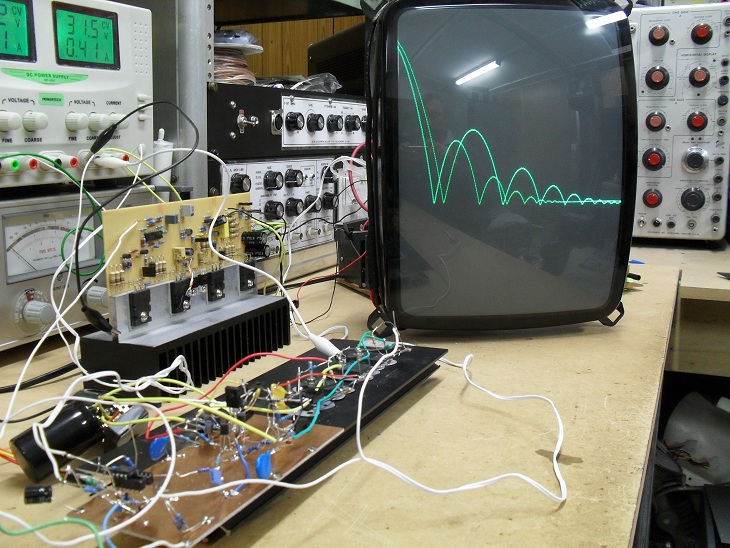
I needed a break this evening from doing PCB layouts for this huge project and decided to fire up the soldering iron instead. I couldn't wait until all the boards are etched so I quickly knocked up a "dead bug" version of the vertical deflection coil current amplifier (the mess in the foreground of the attached picture).


I decided in the end to orientate the CRT vertically. It's looks way cooler this way when simulating and plotting missile trajectories and like stuff. However there is also a sound technical reason. The vertical deflection coil(s) has a great deal more inductance and a much lower self-resonant frequency than does the horizontal deflection coil. In the end I had to frequency compensate the vertical coil driver amplifier for a small signal bandwidth one tenth that of the horizontal coil driver.
In a display such as this, vertical bandwidth is much more important than horizontal bandwidth. The horizontal bandwidth just has to accommodate the horizontal sweep/repetition rate; and that only needs to be quick enough for a flicker-free display.     
So, by flipping the CRT on its side, the slow vertical deflection becomes the horizontal and the fast (comparatively) horizontal deflection becomes the vertical. There was of course another option - I could have just rotated the yoke 90 degrees instead, but as I mentioned already, my preference if for the CRT on its side.

The attached pic shows the prototype monitor displaying my simulation of the trajectory of two bounding balls simultaneously (one ball a little heavier than the other and subjected to a larger constant for gravity). Tomorrow evening I will "dead bug" the colour gun multiplexing and get the individual ball trajectories showing in different colours (and perhaps modify the simulation to simultaneously compute another ball trajectory or two).
 
« Last Edit: April 23, 2013, 11:38:21 pm by GK »
Bzzzzt. No longer care, over this forum shit.........ZZzzzzzzzzzzzzzzz
 

Offline GKTopic starter

  • Super Contributor
  • ***
  • Posts: 2607
  • Country: au
Re: Home Brew Analog Computer System
« Reply #80 on: April 25, 2013, 08:45:34 am »
WOW! I am blown away by all of the discussion this project presentation is generating!  :P  ::)

Here is the final schematic for the horizontal deflection coil driver (utilizing the high inductance, previously vertical, coils of the deflection yoke).

« Last Edit: April 26, 2013, 06:10:12 am by GK »
Bzzzzt. No longer care, over this forum shit.........ZZzzzzzzzzzzzzzzz
 

Offline chickenHeadKnob

  • Super Contributor
  • ***
  • Posts: 1055
  • Country: ca
Re: Home Brew Analog Computer System
« Reply #81 on: April 25, 2013, 11:56:47 am »
WOW! I am blown away by all of the discussion this project presentation is generating!  :P  ::)


careful what you wish for dude. I have been watching your progress and sort of biting my tongue. A slightly evil urge has come over me.

   You see decades ago I became fascinated with the Fermi-Pasta-Ulam problem, which is a seminal problem in nonlinear dynamics from the 50's. It was an early digital simulation done by the Los Almos peeps at a time when people were still playing with analog computers and hybrids. The surprising thing about the FPU problem is that it was a demonstration of a system which had chaotic modes when it was expected to time evolve ergodicly with equi-distribution  of energy. I have always wondered how you could do this simulation with strictly analog computation and have the results graphically displayed in real-time. Now I don't have the chops to make an analog FPU problem simulator so I want you to make it happen for me.
I mean you have all this equipment and ability but nothing interesting to calculate.   >:D
 

Offline GKTopic starter

  • Super Contributor
  • ***
  • Posts: 2607
  • Country: au
Re: Home Brew Analog Computer System
« Reply #82 on: April 25, 2013, 02:10:47 pm »
So how many individual integrators will that problem require then?  ;D I'm assembling into this computer project 30. I still have a ship load of hardware assembly to complete before I can run anything serious. I currently have this machine ~90% designed and ~5% built. The former has been taking nearly all of my free time over the past several months, but should make way for the latter (construction) in another month or two in a major way. Once this thing is built I'll have all the time in the world to study problems to run. However my mathematical background is rather weak, and I require more than just a little revision. That is going to be as much if not more of an endeavor as was designing and building the computer to begin with. I'm currently tracking down and filling a bookshelf with classic analog computing texts (a dozen so far). My current bedtime reading is Albert S. Jackson's Analog Computation
« Last Edit: April 26, 2013, 06:31:58 am by GK »
Bzzzzt. No longer care, over this forum shit.........ZZzzzzzzzzzzzzzzz
 

Offline GKTopic starter

  • Super Contributor
  • ***
  • Posts: 2607
  • Country: au
Re: Home Brew Analog Computer System
« Reply #83 on: April 25, 2013, 02:24:54 pm »
....... and here is the revised/final schematic for the vertical deflection driver amplifier. At ~50kHz it has 10 times the small signal bandwidth of the horizontal deflection driver amplifier.

« Last Edit: April 26, 2013, 06:09:26 am by GK »
Bzzzzt. No longer care, over this forum shit.........ZZzzzzzzzzzzzzzzz
 

Offline baljemmett

  • Supporter
  • ****
  • Posts: 665
  • Country: gb
Re: Home Brew Analog Computer System
« Reply #84 on: April 25, 2013, 03:01:52 pm »
WOW! I am blown away by all of the discussion this project presentation is generating!  :P  ::)

I think you need to chuck in an Arduino, a blinky LED and some obvious design errors if you want real discussion ;)

But seriously, I'm enjoying reading about your progress - analogue computing (hell, analogue anything) is not something I know a busting lot about, so I'm keeping my head down and my ignorance hidden, but I'm fascinated nevertheless.
 

Offline chickenHeadKnob

  • Super Contributor
  • ***
  • Posts: 1055
  • Country: ca
Re: Home Brew Analog Computer System
« Reply #85 on: April 25, 2013, 09:58:01 pm »
So how many individual integrators will that problem require then?  ;D I'm assembling into this computer project 30. I still have a ship load of hardware assembly to complete before I can run anything serious. I currently have this machine ~90% designed and ~5% built. The former has been taking nearly all of my free time over the past several months, but should make way for the latter (construction) in another month or two in a major way. Once this thing is built I'll have all the time in the world to study problems to run.

Well my comment was a sideways query as to how you would implement an FPU simulator, because I don't know how. The original and canonical  FPU problem is 64 idealized and simulated spring-mass units connected in a line so I was thinking 64 oscillators of some sort,  maybe simple RC's or an array of 74HC14's in a ring oscillator configuration. That would be the first step. Next I would need to add in the non-linear terms in a controlled way, thats the second step. Finally how to display what is happening in the system.

Anyway I thought you might have some ideas.
 

Offline GKTopic starter

  • Super Contributor
  • ***
  • Posts: 2607
  • Country: au
Re: Home Brew Analog Computer System
« Reply #86 on: April 26, 2013, 12:55:53 am »
So how many individual integrators will that problem require then?  ;D I'm assembling into this computer project 30. I still have a ship load of hardware assembly to complete before I can run anything serious. I currently have this machine ~90% designed and ~5% built. The former has been taking nearly all of my free time over the past several months, but should make way for the latter (construction) in another month or two in a major way. Once this thing is built I'll have all the time in the world to study problems to run.

Well my comment was a sideways query as to how you would implement an FPU simulator, because I don't know how. The original and canonical  FPU problem is 64 idealized and simulated spring-mass units connected in a line so I was thinking 64 oscillators of some sort,  maybe simple RC's or an array of 74HC14's in a ring oscillator configuration. That would be the first step. Next I would need to add in the non-linear terms in a controlled way, thats the second step. Finally how to display what is happening in the system.

Anyway I thought you might have some ideas.


OK, basic rule of analog computing - most physical systems can be simulated with enough of rather few building blocks, namely, the integrator, the inverting summer and the function generator. The spring mass problem is rather simple (see attached). in it simplest form it is just a double integration in a loop with damping feedback. It requires two inverting summer and two integrator stages. To simulate 64 (does it have to be 64?) of them I would need 128 integrators and 128 summers. You say they were connect in a line? That makes it a fair bit more complex (much more than just summing outputs as the masses of all of the lower units are hanging on and thus influencing the higher units). Sounds like an interesting problem though. The attached simulation just shows three independent spring mass simulations run simultaneously.

Another rule of analog computing; you don't actually need an analog computer as all of its building blocks and be readily simulated and interconnected in SPICE  ;D . However, in comparison, that is hardly any fun. 


EDIT: I don't have the time to search for it right now, but in one of my textbooks a double (series connected) spring mass system is described as part of a car suspension system simulation. From memory the first spring mass represents the weight of the wheel in its entirety and the suspension spring while the second spring mass represents the "spring factor" of the inflated tire and the weight of the tire itself. The solution to the problem you describe could be as simple as expanding upon that problems basic methodology by simply adding to the number of series-connect spring masses.

« Last Edit: April 26, 2013, 06:34:53 am by GK »
Bzzzzt. No longer care, over this forum shit.........ZZzzzzzzzzzzzzzzz
 

Offline chickenHeadKnob

  • Super Contributor
  • ***
  • Posts: 1055
  • Country: ca
Re: Home Brew Analog Computer System
« Reply #87 on: April 26, 2013, 05:23:02 am »


OK, basic rule of analog computing - most physical systems can be simulated with enough of rather few building blocks, namely, the integrator, the inverting summer and the function generator. The spring mass problem is rather simple (see attached). in it simplest form it is just a double integration in a loop with damping feedback. It requires two inverting summer and two integrator stages. To simulate 64 (does it have to be 64?) of them I would need 128 integrators and 128 summers. You say they were connect in a line? That makes it a fair bit more complex (much more than just summing outputs as the masses of all of the lower units are hanging on and thus influencing the higher units). Sounds like an interesting problem though. The attached simulation just shows three independent spring mass simulations run simultaneously.

Another rule of analog computing; you don't actually need an analog computer as all of its building blocks and be readily simulated and interconnected in SPICE  ;D . However, in comparison, that is hardly any fun. 


Thank you for the thoughtful reply. Need to be 64?, well if I want to be true to the original, yes. Enrico Fermi (nobel physics), Stan Ulam mathematician and co-inventer of the hohlraum type of fusion bomb, Pasta a relative nobody computer guy and Mary Tsingou  a mathematician/programmer were researching models of heat diffusion in solids and looked for a simplified model to be simulated on an early digital computer. The mass-springs  in the model are undamped (frictionless). I see in damping in the double spring model in your png, otherwise its on the right track. What I was hoping for was to be able to simulate the  individual mass-springs with a few cheap components, I thought trying to display what is happening would be much more of a challenge. Note that the surprising thing about the FPU simulation is that it never settles down for a broad spectrum of inputs, instead it exhibits chaotic behaviour.

I agree spice is no fun, I wanted the tactile experience of real hardware. My brother gave me a "chaotic pendulum" for christmas many years ago, it is just a magnet hanging from a string and some disk magnets  you position around the base which cause the pendulum to swing in widely different directions and periods. It is fun to play with and I thought a real FPU simulator would be even better. Sort of a high brow mathematical lava lamp. I am a coder and if I was forced to I probably wouldn't use spice, and instead code it up myself. But I don't have to as multiple implementations are available on the net.

Some links:
http://www.scholarpedia.org/article/Fermi-Pasta-Ulam_nonlinear_lattice_oscillations
http://physics.ucsc.edu/~peter/242/FPU-birth-of-nonlinear-science-Lilienfeld.pdf - this is a good intro pdf of lecture slides
 

Offline GKTopic starter

  • Super Contributor
  • ***
  • Posts: 2607
  • Country: au
Re: Home Brew Analog Computer System
« Reply #88 on: April 26, 2013, 06:18:18 am »
Hmmmm..........Problem is if it is un-damped you somehow have to maintain a loop gain of precisely 1, otherwise the oscillations will either grow until the amplifiers saturate or decay altogether. To do this with a real world analog computer you will then need a level detector controlling a multiplier to act as a servo loop to regulate the amplitude of oscillation. However the feedback contribution of the servo leveling loop(s) may corrupt the experiment (there may also be some serious interaction issues too). At this stage I really don't know. Perhaps this is a reason why they had to hang out until someone had finally developed a digital computer that they could play with? 

« Last Edit: April 26, 2013, 06:50:55 am by GK »
Bzzzzt. No longer care, over this forum shit.........ZZzzzzzzzzzzzzzzz
 

Offline GKTopic starter

  • Super Contributor
  • ***
  • Posts: 2607
  • Country: au
Re: Home Brew Analog Computer System
« Reply #89 on: April 26, 2013, 06:27:50 am »
I just deleted and re-posted revised circuits for the vertical and horizontal deflection coil drivers attached to posts 81 and 84.

I ended up modifying the frequency compensation. In the previous iteration(s) I had pole-zero pairs in the coil current-sense negative feedback loop(s) to give greater loop gain at DC, but this compromised the transient response to some degree, producing significant (10%) overshoot to the edges of a full amplitude square wave stimulus due to the zero (a high-pass pole) introduced into the loop response. 

I have now removed the pole-zero pairs in each amplifier circuit to keep the feedback loops 100% DC coupled. This gives the deflection amplifiers an almost perfect transient response without any overshoot. Now I will have to revise the PCB layouts yet again.......damn.
« Last Edit: April 26, 2013, 06:47:44 am by GK »
Bzzzzt. No longer care, over this forum shit.........ZZzzzzzzzzzzzzzzz
 

Offline GKTopic starter

  • Super Contributor
  • ***
  • Posts: 2607
  • Country: au
Re: Home Brew Analog Computer System
« Reply #90 on: April 26, 2013, 06:56:01 am »
I think you need to chuck in an Arduino, a blinky LED and some obvious design errors if you want real discussion ;)


 ;D Well, this project has now grown to the extent that the digital section of this hybrid computer (along with the display unit) will have to be built into a seperate 19" rack which I have acquired. There will literally be hundreds of blinky LED's indicating the status of the logic elements; but definitely no Arduino.
« Last Edit: April 26, 2013, 06:57:35 am by GK »
Bzzzzt. No longer care, over this forum shit.........ZZzzzzzzzzzzzzzzz
 

Offline chickenHeadKnob

  • Super Contributor
  • ***
  • Posts: 1055
  • Country: ca
Re: Home Brew Analog Computer System
« Reply #91 on: April 26, 2013, 07:40:22 am »
Hmmmm..........Problem is if it is un-damped you some how have to maintain a loop gain a precisely 1, otherwise the oscillations will either grow until the amplifiers saturate or decay altogether. To do this with an real world analog computer you will then need level detector controlling a multiplier to act as a servo loop to regulate the amplitude of oscillation. However the feedback contribution of the servo leveling loop(s) may corrupt the experiment. At this stage I really don't know. Perhaps this is a reason why they did it on a digital computer?

Considering active devices was giving me a headache for another related reason. The system to be modelled is adiabatic (I think!), that is once it is charged with its initial energy it neither dissipates nor consumes power, only transfers it loss-lessly among the masses. Obviously  real components can't do this and I don't know how to fix that. Some kind of sealed chamber-calirometer controlling the power input  would be my only guess. That is why I started thinking about RC networks with the only servo loop controlling power in vs power out, but I am no engineer  :P so I just hit the brick wall  |O.  While digital computers can evade most of these road blocks even the digital simulations run into the limit of finite precision due to the sensitive dependence on initial conditions.
 

Offline GKTopic starter

  • Super Contributor
  • ***
  • Posts: 2607
  • Country: au
Re: Home Brew Analog Computer System
« Reply #92 on: April 26, 2013, 10:07:37 am »
Thinking about a bit more with my limited mathematical insight, having skimmed the links that you provided, I think this is an abstract mathematical problem not realizable in a functional analog constructed with real world electronic components and operational amplifiers. It's probably, for all sakes and purposes from a practical perspective, just as feasible as cold fusion in the HAM shack  :P . Moving along now to the next challenge please...................  ;D
« Last Edit: April 26, 2013, 10:17:07 am by GK »
Bzzzzt. No longer care, over this forum shit.........ZZzzzzzzzzzzzzzzz
 

Offline GKTopic starter

  • Super Contributor
  • ***
  • Posts: 2607
  • Country: au
Re: Home Brew Analog Computer System
« Reply #93 on: April 26, 2013, 02:29:22 pm »
Here is the signal preamplifier for the display unit. Two of these will be incorporated into the display unit; one for the X-axis input and one for the Y-axis input. This module gives an oscilloscope-like front-end with a 1M input, an AC/GND/DC input coupling switch, an 11-position 1/2/5 sensitivity switch, a 1-to-0.4 variable sensitivity control, beam/trace positioning pots and a signal inversion switch.

These boards along with the revised PCB's for the horizontal and vertical deflection coil drivers will be going into the etch tank tomorrow morning...........

 
« Last Edit: April 29, 2013, 12:46:08 pm by GK »
Bzzzzt. No longer care, over this forum shit.........ZZzzzzzzzzzzzzzzz
 

Offline GKTopic starter

  • Super Contributor
  • ***
  • Posts: 2607
  • Country: au
Re: Home Brew Analog Computer System
« Reply #94 on: April 29, 2013, 12:52:56 pm »
The two signal pre-amplifiers are almost done..... one is complete and the other still need to be wired. I've assembled the complete pre-amplifiers into their own sub-chassis, which will mount behind the display units from panel. This makes assembly a great deal easier as the wiring to all of the controls does not have to be done inside the case.


Bzzzzt. No longer care, over this forum shit.........ZZzzzzzzzzzzzzzzz
 

Offline GKTopic starter

  • Super Contributor
  • ***
  • Posts: 2607
  • Country: au
Re: Home Brew Analog Computer System
« Reply #95 on: May 05, 2013, 05:57:14 am »
..... chaotic modes....


Well, here is some pseudo chaos in the meanwhile.....


I solved the coupled differential equations of the famous Lorenz system in LTspice and recorded the x and z polar coordinated to a 60 second stereo *.wav file. Now that I have a sound card modified for a response down to DC and have finished building up the deflection amplifiers I can begin plotting some fancy formula solutions on my CRT.

It didn't video real well due to the crappy resolution and frame rate of my camera, but the demonstration is clear enough. I started the mathematical solution with a rather long time constant of integration and slowly ramped it up linearly. So the display begins with the dot produced by the CRT beam apparently randomly and chaotically revolving about the "Lorenz attractor", dancing between the two domains until it becomes fast enough for the displayed image to evolve into the well known "owl face". I also included audio of the summed x and z signals in the video. Sounds kind of spooky once the frequency of oscillation (if that is the correct word) becomes high enough to be audible.


« Last Edit: May 05, 2013, 05:59:45 am by GK »
Bzzzzt. No longer care, over this forum shit.........ZZzzzzzzzzzzzzzzz
 

Offline chickenHeadKnob

  • Super Contributor
  • ***
  • Posts: 1055
  • Country: ca
Re: Home Brew Analog Computer System
« Reply #96 on: May 05, 2013, 10:28:15 pm »
Yup, that looks like the lorenz attractor. Its good to get confirmation that your boards are working. The only demonstration of an analog computer actually being used in anger that I can remember viewing was running the lorenz attractor. The problem of what to do with your machine as it nears completion is only going to get more acute  :'(  That's common to a lot projects where the fun is in the building.

  My father was a boy/teen in Germany during WWII and he was drafted into the FLAKhelfer (anti-aircraft assistant, or auxiliary) mobilization in the last year of the war. He had exceptionally good eyesight and could see and identify aircraft before the others so he was part of the spotting team. They had an optical sight/rangefinder with exaggerated parallax and some kind of analog ballistics computer that compensated for wind and azimuth and other inputs. I  think it may have been mechanical and I doubt it did the predictor/corrector type of aim control like American radar directed guns. He still gets exited talking about those things but he never explained to me how they worked. Not much call for analog anti-aircraft directors these days. Something I have fantasized making is a laser  fly zapper with digital computer vision and control, but then when I add up the work involved my bio computer just directs me to grab  a swatter.
 

Offline GKTopic starter

  • Super Contributor
  • ***
  • Posts: 2607
  • Country: au
Re: Home Brew Analog Computer System
« Reply #97 on: May 07, 2013, 12:51:54 pm »
You mean like one of these:


.... upon interrogation I had to reassure an Air Force cadet leader that the radar dish was no longer operational.


My classic analog computing texts are slowly arriving in the mail. I love Abebooks; you can find almost anything. One book only cost me a dollar. These books are packed with ideas and examples of problems to run. I don't think I'll have any problem finding problems to solve and run once the computer is completely built. Haven't really scratched the surface so far.


Some of these books come from interesting places:


But anyway, here is another simulation in the meanwhile:


« Last Edit: May 07, 2013, 01:03:49 pm by GK »
Bzzzzt. No longer care, over this forum shit.........ZZzzzzzzzzzzzzzzz
 

Offline GKTopic starter

  • Super Contributor
  • ***
  • Posts: 2607
  • Country: au
Re: Home Brew Analog Computer System
« Reply #98 on: June 13, 2013, 12:56:08 pm »
An analog computers brain under construction...................

These are the integrator boards (schematic here: https://www.eevblog.com/forum/projects/glass-diode-photoelectric-effect/msg230406/#msg230406 ).
Turns out that I couldn't etch the boards myself in this quantity cheaper than having them made.

Also got my front panel for the display unit from Front Panel Express. Things are slowly progressing.........
Bzzzzt. No longer care, over this forum shit.........ZZzzzzzzzzzzzzzzz
 

Offline alanb

  • Frequent Contributor
  • **
  • Posts: 344
  • Country: gb
Re: Home Brew Analog Computer System
« Reply #99 on: June 13, 2013, 04:44:50 pm »
I'm constantly amazed by the scale of this project. Are you able to provide an estimate of the total cost and the time that you will have spent on it when complete.


Share me

Digg  Facebook  SlashDot  Delicious  Technorati  Twitter  Google  Yahoo
Smf