Author Topic: Instrumentation Amplifier Modification or Replacement  (Read 21716 times)

0 Members and 1 Guest are viewing this topic.

Offline loop123Topic starter

  • Frequent Contributor
  • **
  • !
  • Posts: 297
  • Country: ca
Instrumentation Amplifier Modification or Replacement
« on: February 15, 2024, 03:17:01 am »
I'd like to change the AMP01 instrumentation amplifier to the top one with best spec ever. First some technical discussions. This is its datasheet and its spectral density graph.

https://www.analog.com/media/en/technical-documentation/data-sheets/amp01.pdf

2017562-0

I know that to convert to Voltage in RMS. Multiply nV/Sqrt(Hz) to the square root of the bandwidth.

Let's use 100Hz bandwidth as example (actual example).

from the graph with spectral density 5 nV/Sqrt (Hz).   V(rms) = 5nV/Sqrt (Hz)  multiply by Sqrt (100) = 5nV * 10 = 0.000000005 x 10 = 0.000000050 V or 50nV.

So the noise is like V(rms) = 50nV.

In my application. I need to run it at 10uV (microVolt) input using 1000Hz-3000Hz  frequency with good noise profile.

What instrumentation amplifier to replace the AMP01 that is the top or the best out there that can use 10uV input with 1000Hz-3000Hz frequency with not visible or minimal noise? 

If possible. The frequency can be 10,000 Hz instead of 1000Hz. Just give the instrumentation amplifier with the highest bandwidth that can do it.

Thank you.
« Last Edit: February 28, 2024, 10:42:49 pm by loop123 »
 

Offline moffy

  • Super Contributor
  • ***
  • Posts: 1740
  • Country: au
Re: Instrumentation Amplifier Modification or Replacement
« Reply #1 on: February 15, 2024, 04:11:08 am »
In such an application, shielding, both thermal and electrical is very important. I found a ground plane top and bottom as well as a shielded box for both electrical and thermal effects is essential. You also need to determine if your PSU is inducing the noise, use a battery supply as a reference to check the difference.
 

Offline loop123Topic starter

  • Frequent Contributor
  • **
  • !
  • Posts: 297
  • Country: ca
Re: Instrumentation Amplifier Modification or Replacement
« Reply #2 on: February 15, 2024, 10:28:45 am »
Ok.

Say. If two instrumentation amplifiers have same nV/sqrt (Hz) lets say 5 nV/Sqrt (Hz). It means they have similar noise at say 1000Hz or 2000Hz bandwidth?

Know the top Instru Amps (INA) model out there that accept differential signal with 1uV to 10uV 1000Hz-2000Hz with very clean output with noises in the nV instead of uV?  What is the lowest spectral density figure available? like is there a 1nV/sqrt (Hz) or even 0.5nV/sqrt (Hz) Instru amps?
 

Offline moffy

  • Super Contributor
  • ***
  • Posts: 1740
  • Country: au
Re: Instrumentation Amplifier Modification or Replacement
« Reply #3 on: February 15, 2024, 10:58:37 am »
Ok.

Say. If two instrumentation amplifiers have same nV/sqrt (Hz) lets say 5 nV/Sqrt (Hz). It means they have similar noise at say 1000Hz or 2000Hz bandwidth?

Know the top Instru Amps (INA) model out there that accept differential signal with 1uV to 10uV 1000Hz-2000Hz with very clean output with noises in the nV instead of uV?  What is the lowest spectral density figure available? like is there a 1nV/sqrt (Hz) or even 0.5nV/sqrt (Hz) Instru amps?

Depends on the input impedance of the circuit. The THAT1512 can have 1nV/hz^0.5 but that is with zero input impedance and 60dB of gain, but current noise can easily become the dominant factor at around 1k ohm perhaps lower, in which case a JFET input amp is a better choice. What you are seeing though is induced pickup and you won't even get close to the performance of a good instrument amp if you don't pay serious detailed attention to what was mentioned previously, both electrical and thermal shielding as well as power supply noise. You should also aim for a true differential input to try and maximise CMRR.
« Last Edit: February 15, 2024, 08:37:39 pm by moffy »
 

Offline loop123Topic starter

  • Frequent Contributor
  • **
  • !
  • Posts: 297
  • Country: ca
Re: Instrumentation Amplifier Modification or Replacement
« Reply #4 on: February 15, 2024, 12:15:46 pm »

No problem with power supplies as I used batteries only. The circuit has metal cover on all corners and I may use Faraday cage (know where to get these to enclose projects?) About thermal shielding.  Did you mean putting it in very cold aircon? How to do thermal shielding?

It is true differential input with about 10kOhm source impedance. So what state of the art INA (Instrumentation Amp) that can accept high input impedance, etc. It should be something that is significantly better than the AMP01. Actually it will be used as EEG with microVolt input but with 1000Hz frequency so I can lessen the gain when time to switch to milliVolt EMG and still have the 1000Hz-2000Hz capability. I already have the finished product but it uses AMP01 so for my project. I'll replace the amps to the best one in the world. I have 2 units. One is for experiment. Don't worry about Galvanic isolation because it is all purely powered by 1.2V rechargeable Eneloop batteries.
 

Offline CaptDon

  • Super Contributor
  • ***
  • Posts: 1740
  • Country: is
Re: Instrumentation Amplifier Modification or Replacement
« Reply #5 on: February 15, 2024, 02:52:06 pm »
You are getting so bogged down in numbers and math and 'best in the world' opamps. I worked in the hospital biomed O.R. field for around 5 years and simply stated "You don't need the best in the world opamps" to accomplish your tasks. EEG machines with perfectly usable results have been around for decades. EEG brainwave monitors and ECG heart monitors have relatively standard run of the mill parts. The key ingredient is shielding not only of the equipment and its connections but also of the other equipment within the room including the wiring in the walls. The thermal noise of the resistors in your bio-amplifier circuit may well make the need for a 'super noise free opamp' pointless. Take a case in point, the 20 meter ham band at 14MHz. A receive preamplifier can help, however, the atmospheric noise floor is so high that an 'ultra low noise preamplifier' is not needed and even a noisy poorly designed tube preamplifier gives as good of results as can possibly be obtained. It seems you are chasing a problem in mathematical details and not a problem that exists in the real world which every manufacturer of biomedical equipment has already solved. A better antenna beats a preamp every time!! Maybe there is a better way to capture your signals like a pre-amplified probe?
Collector and repairer of vintage and not so vintage electronic gadgets and test equipment. What's the difference between a pizza and a musician? A pizza can feed a family of four!! Classically trained guitarist. Sound engineer.
 

Offline Andy Chee

  • Frequent Contributor
  • **
  • Posts: 686
  • Country: au
Re: Instrumentation Amplifier Modification or Replacement
« Reply #6 on: February 15, 2024, 03:22:58 pm »
On a slightly different tangent, I understand that you will be using your amplifier for a brain computer interface.  I hope you understand that EEG signals are inherently noisy (especially in unknown/uncontrolled physical environments), and much of the clean up occurs in signal processing software rather than hardware.

Of course it helps to have clean hardware in the first place, but there will be a point of diminishing returns.
 

Online Kleinstein

  • Super Contributor
  • ***
  • Posts: 14210
  • Country: de
Re: Instrumentation Amplifier Modification or Replacement
« Reply #7 on: February 15, 2024, 04:50:41 pm »
For a 10 K range source impedance the amp01 looks not that bad. The noise resistance (= voltage noise divided by current noise density) is at some 35 Kohms and thus not that far off the source impedance.
In some cases the current noise can be actually a bit larger, as not all datasheets handle the correlation between the input right.
The very low voltage noise types (e.g. AD8428) are not suitable.

Just have a look at the AD webside to get an idea, what is available.

With some 5 nV/Sqrt(Hz) to beat, there could also be JFET based amplifiers as an option. If one really wants to and the main interest with higher frequencies, one could consider a discrete JFET version. This way could offer less noise, but is quite some effort.
 

Offline loop123Topic starter

  • Frequent Contributor
  • **
  • !
  • Posts: 297
  • Country: ca
Re: Instrumentation Amplifier Modification or Replacement
« Reply #8 on: February 16, 2024, 11:19:40 pm »
Ignore the initial message because I interchanged the reference and ground. You see. In EMG, the reference is the real ground. While in EEG the so called "reference" is connected to V- of the differential amplifier. So in the Netech EEG simulator. I connected the amplifier ground to the REF socket when it should be the V- of the amplifier that should be connected to the Netech REF.

With this correction. I got the following waveform with 10uV, 60Hz, 100Hz bandwidth selectded at main amp with 50000 gain

2020604-0

The following with 1000Hz bandwidth selected:

2020610-1

So my simple goal is to replace the amplifier to get rid of the noises at 1000Hz.

Usually in EEG, the bandwidth used is only 40Hz. In EMG, it's 1000Hz. In my Brain Computer Interface project. I just want not to keep adjusting the bandwidth switch when adjusting and to zoom the milliVolt to microVolt also at will so I need to upgrade the amplifier.

So please give those amps suggestions that is much better than the AMP01 in the unit. Thanks.
 

Offline loop123Topic starter

  • Frequent Contributor
  • **
  • !
  • Posts: 297
  • Country: ca
Re: Instrumentation Amplifier Modification or Replacement
« Reply #9 on: February 17, 2024, 05:21:56 am »
For a 10 K range source impedance the amp01 looks not that bad. The noise resistance (= voltage noise divided by current noise density) is at some 35 Kohms and thus not that far off the source impedance.
In some cases the current noise can be actually a bit larger, as not all datasheets handle the correlation between the input right.
The very low voltage noise types (e.g. AD8428) are not suitable.

Where did you get 35Kohm exactly?  Also in the AMP01 datasheet below. Why is the noise greater at Gain=1 compared to say Gain=100? Is it not as the gain goes higher, there should be more noise?

And why should the source impedance be close to the noise resistance?
2020886-0

Quote
Just have a look at the AD webside to get an idea, what is available.

With some 5 nV/Sqrt(Hz) to beat, there could also be JFET based amplifiers as an option. If one really wants to and the main interest with higher frequencies, one could consider a discrete JFET version. This way could offer less noise, but is quite some effort.

What you mean quite effort? is there no single discrete JFET that is inside single chip so you dont have to buld the transistors from scratch. So without going into discrete JFET. There is no way to  get lower than noise of 5nV(sqrt(Hz))
 

Offline moffy

  • Super Contributor
  • ***
  • Posts: 1740
  • Country: au
Re: Instrumentation Amplifier Modification or Replacement
« Reply #10 on: February 17, 2024, 06:12:31 am »
The AMP01 really is quite good. It has 5nV/sqrt(Hz) voltage noise and 0.15pA/sqrt(Hz) current noise which means that if the input impedance is 33.33k then the current noise and voltage noise are equivalent. Excellent CMRR and true differential inputs. The quoted noise of the opamp is referred to the input, so you multiply the input noise by the gain to get the output noise. The input referred noise drops at higher gains because the low noise input stage dominates (where most of the gain occurs) and the noiser later stages become less significant.
Nice results.
 

Online Kleinstein

  • Super Contributor
  • ***
  • Posts: 14210
  • Country: de
Re: Instrumentation Amplifier Modification or Replacement
« Reply #11 on: February 17, 2024, 07:58:00 am »
BJT based amplifiers are somewhat limited in the noise figure they can reach. When they are made for lower voltage noise the current noise goes up. The noise figure is best when the source impedance matched the ration of voltage noise to current noise (provided the 2 are not correlated).

JFET amplifiers have much lower current noise and can reach better noise figures. However it takes some effort to get low voltage noise and the low noise figures are for higher impedance.  There are integrated FET based instrumentation amplifiers, but they may not be better than 5 nV/sqrt(Hz). The best bet here seems to be the LTC6373 with some 8 nV/sqrt(Hz).
Using discrete FETs could get lower noise, though with extra effort. There may be ready made hybirds or modules available, though usually not cheap.


p.s.
The AD8421 is another good BJT based INA, more suitable for low source impedance. Depending on the details (the specs for the current noise are sometimes a bit fishy) it could be slightly lower noise than the amp01.
« Last Edit: February 17, 2024, 08:02:17 am by Kleinstein »
 

Offline loop123Topic starter

  • Frequent Contributor
  • **
  • !
  • Posts: 297
  • Country: ca
Re: Instrumentation Amplifier Modification or Replacement
« Reply #12 on: February 17, 2024, 09:01:30 am »
In skin electrode application, you abrade the skin to 5kOhm.

Why is it best to match source impedance with voltage/current noise? It is not about the concept of voltage divider where it is better to match input and source resistance so either will take half the voltage, is it?

Lets take the actual example of the skin needing to be 5kOhm. But the voltage and current noise resistance of the AMP01 is really 33kOhm as one of you computed. So why is the source impedance better at 33kOhm instead with 5kOhm (which should really be better so the voltage would be taken up more by the input (related to the concept where input impedance) but must be much higher. Pls give actual computations of 5kOhm vs 33kOhm.

I need to understand this bec my next project is building an active amplifier so you dont have to abrade the skin and it can have good noise even at higher resistance.

Also its needed to find upgrade to the AMP01 to match 5kOhm source impedance where you cant see any noise at 10 microVolt and 1000Hz.

Without abraiding the skin, there would be more noise in principle, is the noise that significant? Lets see in your computations.

Thanks a lot.
 

Offline moffy

  • Super Contributor
  • ***
  • Posts: 1740
  • Country: au
Re: Instrumentation Amplifier Modification or Replacement
« Reply #13 on: February 17, 2024, 09:13:12 am »
Why is it best to match source impedance with voltage/current noise? It is not about the concept of voltage divider where it is better to match input and source resistance so either will take half the voltage, is it?

Lets take the actual example of the skin needing to be 5kOhm. But the voltage and current noise resistance of the AMP01 is really 33kOhm as one of you computed. So why is the source impedance better at 33kOhm instead with 5kOhm (which should really be better so the voltage would be taken up more by the input (related to the concept where input impedance) but must be much higher. Pls give actual computations of 5kOhm vs 33kOhm.


33k is just the impedance point where current noise equals the voltage noise, it isn't an optimal point. Below the 33k voltage noise dominates, above 33k current noise will dominate. Better than the AMP01 for your application would take some work because you need very high input CMRR of a true differential input and that can be challenging using discretes like the JFE2140: https://www.ti.com/product/JFE2140
which have excellent voltage and current noise but it is getting the high CMRR of the AMP01 as well for what at the end might only be a modest improvement in noise.
 

Online Kleinstein

  • Super Contributor
  • ***
  • Posts: 14210
  • Country: de
Re: Instrumentation Amplifier Modification or Replacement
« Reply #14 on: February 17, 2024, 10:12:14 am »
The matching to the voltage noise to current noise ratio is about the point where the amplifier has the best noise figure. It is not about adding resistance to the input to match, but about where the amplifier would be at it's best. One would match something like a transformer if one uses it, as there no exra noise is added. The amp01 may still be OK with a 5 K source impedance.  Because of the 2 inputs to current noise part would ideally need more than just 1 number for a full charactirization and both sides would contribute. There is a tendency for datasheets to be a bit optimistic with the current noise.
It is just that if one is well off, chances are to find a better other amplifier. If below 70% the noise resistance could use 2 amplifiers in parallel could reduce the noise.

The AD8421 would be a solution that has it's best noise figure at some 16 K, kind of close to 2 x amp01 in parallel. The noise figure is similar, just made for a difference source impedance.

With 33 K or source impedance the amp01 would give 5 nV from the voltage noise and a similar noise from the current noise. So some 7 nV/sqrt(Hz) total. With 5 K source impedance the current noise part would be smaller and the total noise more like 5.5 nV/sqrt(Hz). In addition there is also just the noise from the source resistance (e.g. some 10 nV/sqrt(Hz) for 6 K).  So the overall noise can still to a large part from from the source impedance and not from the amplifier. So the possible advantage from a better amplifier is limited.
 

Offline Zero999

  • Super Contributor
  • ***
  • Posts: 19527
  • Country: gb
  • 0999
Re: Instrumentation Amplifier Modification or Replacement
« Reply #15 on: February 17, 2024, 11:15:27 am »
All your threads appear to be about the same project. You'll get much better quality replies if you keep it all in one thread, rather than starting so many. I've completely lost track of it.

It appears as though you lack adequate filtering for mains frequencies. The input should have a passive, low pass filter, to get rid of RF and mains harmonics, followed by active filtering to get rid of the interference from the mains itself.
 

Offline loop123Topic starter

  • Frequent Contributor
  • **
  • !
  • Posts: 297
  • Country: ca
Re: Instrumentation Amplifier Modification or Replacement
« Reply #16 on: February 17, 2024, 12:34:07 pm »
The matching to the voltage noise to current noise ratio is about the point where the amplifier has the best noise figure. It is not about adding resistance to the input to match, but about where the amplifier would be at it's best. One would match something like a transformer if one uses it, as there no exra noise is added. The amp01 may still be OK with a 5 K source impedance.  Because of the 2 inputs to current noise part would ideally need more than just 1 number for a full charactirization and both sides would contribute. There is a tendency for datasheets to be a bit optimistic with the current noise.
It is just that if one is well off, chances are to find a better other amplifier. If below 70% the noise resistance could use 2 amplifiers in parallel could reduce the noise.

The AD8421 would be a solution that has it's best noise figure at some 16 K, kind of close to 2 x amp01 in parallel. The noise figure is similar, just made for a difference source impedance.

With 33 K or source impedance the amp01 would give 5 nV from the voltage noise and a similar noise from the current noise. So some 7 nV/sqrt(Hz) total. With 5 K source impedance the current noise part would be smaller and the total noise more like 5.5 nV/sqrt(Hz). In addition there is also just the noise from the source resistance (e.g. some 10 nV/sqrt(Hz) for 6 K).  So the overall noise can still to a large part from from the source impedance and not from the amplifier. So the possible advantage from a better amplifier is limited.

I spent many hours reading about current noise vs voltage noise. The dogma seems to be "thermal noise increases with a larger resistance value, whereas current noise decreases when resistance increases."

A web site mentioned this is just a myth. Maybe there are circuits where the above applies and there are other circuits where the following applies? How to know which circuit applies to the dogma and myth belows? Thanks.

https://www.analog.com/en/resources/technical-articles/11-myths-about-analog-noise-analysis.html

"
8. The Amplifier with the Lowest Voltage Noise Is the Best Choice

When choosing an op amp, the voltage noise is often the only noise specification considered by the designer. It is important not to overlook the current noise as well. Except in special cases such as input bias current compensation, the current noise is typically the shot noise of the input bias current: in = √2 × q × IB. The current noise is converted to a voltage via the source resistance, so when there is a large resistance in front of the amplifier input, the current noise can be a larger noise contributor than the voltage noise. The typical case where current noise is a problem is when a low noise op amp is used with a large resistance in series with the input. For example, consider the ADA4898-1 low noise op amp with a 10 kΩ resistor in series with the input. The voltage noise of the ADA4898-1 is 0.9 nV/√Hz, the 10 kΩ resistor has 12.8 nV/√Hz, and the 2.4 pA/√Hz current noise times the 10 kΩ resistor is 24 nV/√Hz, the largest noise source in the system. In cases like this, where the current noise dominates, it is often possible to find a part with lower current noise and thereby reduce the noise of the system. This is especially true for precision amplifiers, but there are high speed FET input op amps that can help in high speed circuits as well. For example, instead of choosing the ADA4898-1 and not getting the benefit of the 0.9 nV/√Hz voltage noise, a JFET input amplifier such as the AD8033 or the ADA4817-1 could have been chosen.".


What kind of circuit where as the resistance increases, the current noise decreases?

What kind of circuit where as the resistance increases, the current noise also increases?
« Last Edit: February 17, 2024, 02:52:37 pm by loop123 »
 

Offline Terry Bites

  • Super Contributor
  • ***
  • Posts: 2393
  • Country: gb
  • Recovering Electrical Engineer
Re: Instrumentation Amplifier Modification or Replacement
« Reply #17 on: February 17, 2024, 04:05:08 pm »
If you can live with switching noise, a "zero drift" amp offers the lowest 1/f noise. For very low level measurments you can't polish off all the common mode with the INA. You boost the apparent cmrr by floating the input. That keeps cm noise from the measurement side out of your front end. Iso amps are not noted for their DC precsion so ideally you digitize before the isolation. I made just such an amp with an icoupler, an AD7400 and a home brew zero drift INA. These days I'd just chuck in a 32bit ADC, eg ADS126x
 

Offline loop123Topic starter

  • Frequent Contributor
  • **
  • !
  • Posts: 297
  • Country: ca
Re: Instrumentation Amplifier Modification or Replacement
« Reply #18 on: February 17, 2024, 09:52:17 pm »

If replacing the AMP01 won't make significant improvement in the remaining noises. Will using active electrodes where the amplifier is in the electrode itself offer much more improvement?

I don't want to abrade skin before use. They say when you use active electrodes, you don't have to abrade the skin to lower resistance to 5kOhm from 30kOhm?

Btw.. I use only batteries in my units so no need for any passive, low pass filter, to get rid of RF and mains harmonics, followed by active filtering to get rid of the interference from the mains itself. The only interference is Radio frequency from air, but can this get into the unit when there are already bandpass filters in the unit such as when selecting the 1000Hz filter switch should filter the higher frequency already. For power line capacitive coupling interference. I always unplug all cables near the area and I don't see any interference from capacitive coupling at all.

I got the units at bargain because the company which uses them think it's defective. I spent the last threads fixing it (which is not connected to the topic here). And now it's fully fixed. So, I'm now focusing on the use and replacing the AMP01 if possible, because of noises at 10microVolt input at 1000Hz frequency.
 

Offline moffy

  • Super Contributor
  • ***
  • Posts: 1740
  • Country: au
Re: Instrumentation Amplifier Modification or Replacement
« Reply #19 on: February 18, 2024, 01:53:35 am »
I don't know how well the skin is modeled by a resistor but at 25C a resistor of 5k has a spectral noise of 9nV/sqrt(Hz) and 30k has a spectral noise density of 22nV/sqrt(Hz) both well above the voltage noise of 5nV/sqrt(Hz) of the AMP01. Resistors generate thermal noise, hence the temperature dependence, even when nothing is attached. But it depends on what the noise model of skin looks like, there probably are capacitances at least that limit bandwidth.
 

Offline loop123Topic starter

  • Frequent Contributor
  • **
  • !
  • Posts: 297
  • Country: ca
Re: Instrumentation Amplifier Modification or Replacement
« Reply #20 on: February 18, 2024, 08:25:43 am »
Most explanations about needing low impedance in the skin is so that there will not be voltage divider where the electrode would soak up some voltage making the signal going to amplifier lower. So the negative effect is not more about getting lesser voltage but about the noise?

2022128-0

I used an El-check electrode checker to measure my skin impedance. The led that lights up is about 10k-20k Ohm.

I read about Active Electrodes in the following. How would getting active electrodes eliminate the 10k-20k Ohm impedance since the Active electrodes use electrodes too?  And the AMP01 has input impedance of greater than 20,000 MegaOhm as it the datasheet mentioned. So even if the skin impedance is 50kOhm. Voltage divider would still make the AMP01 take up 99% of the voltage. Isn't it?

https://zeto-inc.com/blog/active-and-passive-electrodes-what-are-they-pros-cons/

2022134-1

If the advantage is just the cable not picking  up intereference. Then just use notch filter or bandpass filter to handle it. Isn't it?

So what is the real advantage of active electrodes?
« Last Edit: February 18, 2024, 08:27:22 am by loop123 »
 

Offline Andy Chee

  • Frequent Contributor
  • **
  • Posts: 686
  • Country: au
Re: Instrumentation Amplifier Modification or Replacement
« Reply #21 on: February 18, 2024, 08:40:28 am »
If the advantage is just the cable not picking  up intereference. Then just use notch filter or bandpass filter to handle it. Isn't it?
No.  It completely depends on what causes the interference.

For example, if it is mains noise, then yes, a notch filter may work.  But if it is noise from a computer power supply, then probably not.  And what if it's noise coming unidentified the location? (e.g. motor interference from nearby tram/train power lines)

In summary, if you cannot identify where the interference is coming from, then active electrodes are a good solution.
 

Offline loop123Topic starter

  • Frequent Contributor
  • **
  • !
  • Posts: 297
  • Country: ca
Re: Instrumentation Amplifier Modification or Replacement
« Reply #22 on: February 18, 2024, 08:58:12 am »
If the advantage is just the cable not picking  up intereference. Then just use notch filter or bandpass filter to handle it. Isn't it?
No.  It completely depends on what causes the interference.

For example, if it is mains noise, then yes, a notch filter may work.  But if it is noise from a computer power supply, then probably not.  And what if it's noise coming unidentified the location? (e.g. motor interference from nearby tram/train power lines)

In summary, if you cannot identify where the interference is coming from, then active electrodes are a good solution.

The whole unit is powered by batteries. How can computer power supply cause interference? unless by means of EMI? Do you have illustrations of waveforms of common causes of the noises? They are easy to recognize. Even just running a sine wave generator will make them show  up, Isn't it?

How much would it cost to get a Faraday cage the size of person like a telephone booth?
 

Online Kleinstein

  • Super Contributor
  • ***
  • Posts: 14210
  • Country: de
Re: Instrumentation Amplifier Modification or Replacement
« Reply #23 on: February 18, 2024, 09:02:46 am »
The loss in signal amplitude should not be an issue: the amplifier input impedance should be well larger than 10 K and also the capacitive loading from a shielded cable is not that much, unless one is interested in the really high frequencies.

EMI can be a point - it is a bit tricky to design a high impedance filter to keep EMI away from the amplfier.  Once the very high frequency EMI part hits an amplifier it can get demodulated and effect the frequency band of interrest. After that filtering can no longer separate it from the signal.

It may be relevant how good the amplifier can tolerate RF band interference (e.g. WLAN, mobile phones, TV signals, radio). Not all amplifiers react the same way in this respect.
If really deparate one could have an RF receiver to detect the interferening signal and than subtract it. Still tricky when the cables move.

I see an only moderate advantage for active electrodes - maybe a reason to charge more money for them  >:D .

Adding shielding at least adds inconvenience - like move to a special room instead of moving the intrument to the patients room. A shilded room would also need filtering for the supplies and light. RF tight doors are also a thing that is not easy.
 

Offline Andy Chee

  • Frequent Contributor
  • **
  • Posts: 686
  • Country: au
Re: Instrumentation Amplifier Modification or Replacement
« Reply #24 on: February 18, 2024, 09:12:58 am »
unless by means of EMI? Do you have illustrations of waveforms of common causes of the noises? They are easy to recognize. Even just running a sine wave generator will make them show  up, Isn't it?
No.  Sometimes EMI has a known pattern.  But EMI can equally be random.

If you don't want to use a faraday cage, then you should analyse the surrounding EMI in your intended operating environment, so that either;

a) design the hardware to cope with the environment, or
b) program the EEG/EMG software with your EMI analysis, and the software will do the noise reduction for you.

https://eeglab.org/tutorials/ConceptsGuide/Setting_up_your_EEG_lab.html

https://www.ncbi.nlm.nih.gov/pmc/articles/PMC6312138/pdf/june-17-10.pdf
« Last Edit: February 18, 2024, 09:16:49 am by Andy Chee »
 

Offline loop123Topic starter

  • Frequent Contributor
  • **
  • !
  • Posts: 297
  • Country: ca
Re: Instrumentation Amplifier Modification or Replacement
« Reply #25 on: February 18, 2024, 09:38:49 am »

Ok. I'll get an active electrode then. But I'm being quoted for $2000 just for one electrode with the 9V supply box.

Can you guys teach me how to create an active electrode.

Where do we begin? What chip to use? Can it be bigger like an INA114 so imagine your electrode look like  a matchbox.. or should it be miniaturized chip? What is commonly used?
 

Offline Andy Chee

  • Frequent Contributor
  • **
  • Posts: 686
  • Country: au
Re: Instrumentation Amplifier Modification or Replacement
« Reply #26 on: February 18, 2024, 09:42:16 am »
Simple active electrode here

https://www.olimex.com/Products/EEG/Electrodes/EEG-AE/open-source-hardware

I haven't analysed whether it's compatible with your existing bioamplifier.
 

Offline loop123Topic starter

  • Frequent Contributor
  • **
  • !
  • Posts: 297
  • Country: ca
Re: Instrumentation Amplifier Modification or Replacement
« Reply #27 on: February 18, 2024, 11:21:57 am »
unless by means of EMI? Do you have illustrations of waveforms of common causes of the noises? They are easy to recognize. Even just running a sine wave generator will make them show  up, Isn't it?
No.  Sometimes EMI has a known pattern.  But EMI can equally be random.

If you don't want to use a faraday cage, then you should analyse the surrounding EMI in your intended operating environment, so that either;

a) design the hardware to cope with the environment, or
b) program the EEG/EMG software with your EMI analysis, and the software will do the noise reduction for you.

https://eeglab.org/tutorials/ConceptsGuide/Setting_up_your_EEG_lab.html

https://www.ncbi.nlm.nih.gov/pmc/articles/PMC6312138/pdf/june-17-10.pdf

Say. Is Mathcad compatible with direct output like you display in Audacity? or can it only accept proprietary files? can you use Mathcad on direct output to filter certain artifacts or interferences?

Besides Mathcad or maybe EEGlab. What is the most advanced post processing software that can remove for example ECG artifacts when you are doing EMG etc?
 

Offline Andy Chee

  • Frequent Contributor
  • **
  • Posts: 686
  • Country: au
Re: Instrumentation Amplifier Modification or Replacement
« Reply #28 on: February 18, 2024, 12:05:17 pm »
Say. Is Mathcad compatible with direct output like you display in Audacity? or can it only accept proprietary files? can you use Mathcad on direct output to filter certain artifacts or interferences?
I don't use Mathcad, so I don't know for sure.  But if it doesn't have a compatibility layer for importing generic file formats, you could probably use Python to program something to translate the file format.

Quote
Besides Mathcad or maybe EEGlab. What is the most advanced post processing software that can remove for example ECG artifacts when you are doing EMG etc?
Hard to say.  Normally a researcher cannot afford to spend money on multiple software to compare features.  Normally a researcher learns to use whatever the university or hospital is using.

Given that you are asking about amplifier repair, I am guessing you don't want to spend money on software either.  In which case, I highly recommend open-source projects such as EEGlab.
 

Offline loop123Topic starter

  • Frequent Contributor
  • **
  • !
  • Posts: 297
  • Country: ca
Re: Instrumentation Amplifier Modification or Replacement
« Reply #29 on: February 18, 2024, 03:17:59 pm »
unless by means of EMI? Do you have illustrations of waveforms of common causes of the noises? They are easy to recognize. Even just running a sine wave generator will make them show  up, Isn't it?
No.  Sometimes EMI has a known pattern.  But EMI can equally be random.

Just to clarity. I asked if just running a sine wave generator will make the interferences show up. And you said "No.  Sometimes EMI has a known pattern.  But EMI can equally be random". But if you run the sine wave for 1 hour and no interference, then chances are there is just no interference or not constant enough to disturb your output that you get for only 2 minutes, right?

Quote
Simple active electrode here

https://www.olimex.com/Products/EEG/Electrodes/EEG-AE/open-source-hardware

I haven't analysed whether it's compatible with your existing bioamplifier.

Are you saying that active electrodes can only be made by a company who has to miniaturize the chips and they can't be built DIY like us? Why can't you use for example an INA114 and put it in a small matchbox and place it on your skin directly with electrode cup glued to the matchbox and not using any cable before the preamp?
 

Offline Andy Chee

  • Frequent Contributor
  • **
  • Posts: 686
  • Country: au
Re: Instrumentation Amplifier Modification or Replacement
« Reply #30 on: February 18, 2024, 03:37:49 pm »
unless by means of EMI? Do you have illustrations of waveforms of common causes of the noises? They are easy to recognize. Even just running a sine wave generator will make them show  up, Isn't it?
No.  Sometimes EMI has a known pattern.  But EMI can equally be random.

Just to clarity. I asked if just running a sine wave generator will make the interferences show up. And you said "No.  Sometimes EMI has a known pattern.  But EMI can equally be random". But if you run the sine wave for 1 hour and no interference, then chances are there is just no interference or not constant enough to disturb your output that you get for only 2 minutes, right?
No, that's incorrect.  A sinewave only contains one single frequency.  EMI can potentially contain many frequencies, all at the same time, and different amplitudes.

Quote
Quote
Simple active electrode here

https://www.olimex.com/Products/EEG/Electrodes/EEG-AE/open-source-hardware

I haven't analysed whether it's compatible with your existing bioamplifier.

Are you saying that active electrodes can only be made by a company who has to miniaturize the chips and they can't be built DIY like us? Why can't you use for example an INA114 and put it in a small matchbox and place it on your skin directly with electrode cup glued to the matchbox and not using any cable before the preamp?
No, I am not saying that at all.  Yes, you could put INA114 directly on the skin to make your own active electrode. 

Remember though, due to the heavy weight of large active probes, they tend to wobble and move around on the skin, so you may need to use a strap or something to hold it onto the head/face or whatever you're measuring.  A wobbling electrode will create a noisy signal.
 

Offline loop123Topic starter

  • Frequent Contributor
  • **
  • !
  • Posts: 297
  • Country: ca
Re: Instrumentation Amplifier Modification or Replacement
« Reply #31 on: February 18, 2024, 09:34:35 pm »
unless by means of EMI? Do you have illustrations of waveforms of common causes of the noises? They are easy to recognize. Even just running a sine wave generator will make them show  up, Isn't it?
No.  Sometimes EMI has a known pattern.  But EMI can equally be random.

Just to clarity. I asked if just running a sine wave generator will make the interferences show up. And you said "No.  Sometimes EMI has a known pattern.  But EMI can equally be random". But if you run the sine wave for 1 hour and no interference, then chances are there is just no interference or not constant enough to disturb your output that you get for only 2 minutes, right?
No, that's incorrect.  A sinewave only contains one single frequency.  EMI can potentially contain many frequencies, all at the same time, and different amplitudes.

If that's the case. How come the output doesn't show this "potentially contain many frequencies, all at the same time, and different amplitudes."?  The output is all sine wave single frequency. The following is different bandwidth selected (main unit uses 2 pole Butteworth filters), and it's all uniform sine wave even for 20 minutes and all day.

10 microvolt input, 90Hz signal, 50000 gain, 100Hz bandwidth selected:

2023058-0

10 microvolt input, 90Hz signal, 50000 gain, 1000Hz bandwidth selected:

2023064-1

10 microvolt input, 90Hz signal, 50000 gain, 3000Hz bandwidth selected:

2023070-2
 

Online Kleinstein

  • Super Contributor
  • ***
  • Posts: 14210
  • Country: de
Re: Instrumentation Amplifier Modification or Replacement
« Reply #32 on: February 18, 2024, 10:23:26 pm »
The actual EMI background can vary from location to location.  The cableing and local configuration can effect which frequencies are picked up strong. Also the circuit can be more sensitive to some frequencies and less to others.  So while there is a mix of different frequencies, one may well end up with 1 frequency to dominate. However this can also change over time. It can also as well look like noise or one can get a radio program.

A uniform sine like background could indicate one specific source of interference. One may be able to identify and eliminate it.
In the old times classic such frequencies where the CRT horizontal frequencies. Today SMPS are common sources. Even if the testinstrument is battery powered it likely includes some SMPS.

A shielded passive probe may not be that different when it comes to sensitivity to EMI. In a difficult environment both version will struggle and in a quite environment both should work OK.  The extra weight at the electrodes could also be a real hassel and limited size may mean less EMI filtering than at a good central amplifier.
 

Offline Andy Chee

  • Frequent Contributor
  • **
  • Posts: 686
  • Country: au
Re: Instrumentation Amplifier Modification or Replacement
« Reply #33 on: February 19, 2024, 04:10:57 am »
If that's the case. How come the output doesn't show this "potentially contain many frequencies, all at the same time, and different amplitudes."?  The output is all sine wave single frequency. The following is different bandwidth selected (main unit uses 2 pole Butteworth filters), and it's all uniform sine wave even for 20 minutes and all day.
I can guarantee that if you took your equipment down to the train station (electric train) and measure the EMI again, you will definitely get something different!
 

Offline loop123Topic starter

  • Frequent Contributor
  • **
  • !
  • Posts: 297
  • Country: ca
Re: Instrumentation Amplifier Modification or Replacement
« Reply #34 on: February 19, 2024, 07:26:10 am »
If that's the case. How come the output doesn't show this "potentially contain many frequencies, all at the same time, and different amplitudes."?  The output is all sine wave single frequency. The following is different bandwidth selected (main unit uses 2 pole Butteworth filters), and it's all uniform sine wave even for 20 minutes and all day.
I can guarantee that if you took your equipment down to the train station (electric train) and measure the EMI again, you will definitely get something different!

The 60Hz AC noises are only present if the main amp is not connected to any source (like a sine wave generator). See below. But if it connected to any source, there is no interference. So how do you characterize (or compute) the strength of interference before the sine wave input can be affected? I guess the 10 microvolt sine wave generator has same strength as the skin 10 microvolt, isn't it.. since they are 10 microvolt.

The following is when no leads were connected. I didn't disconnect the extension wire in table (so there is 60Hz AC capacitive coupling or electric field), gain of 10000, 1000Hz bandwidth

2023469-0

The following is when gain is adjusted from 10000 to 5000. Why is there less noise?

2023475-1

The following is when Audacity is zoomed to show the 60Hz AC waveforms

2023481-2

When 11 feet cable with open end was connected, the following is the result:

2023487-3

The following with sine wave generator inputted 10 microvolt, 50Hz, 5000 gain, 60 Hz AC on (extension plugged in),  1000Hz Bandwidth

2023493-4

The following when extension cable unplugged (no 60Hz AC (extension wire unplugged))

2023499-5

When there is sine wave generator input, the output is not affected anymore whether the extension wire is plugged (with capacitive coupling) and not plugged (with no capacitive coupling). So what can you say about any built in filters that activates when there is sine wave input??
 

Offline Andy Chee

  • Frequent Contributor
  • **
  • Posts: 686
  • Country: au
Re: Instrumentation Amplifier Modification or Replacement
« Reply #35 on: February 19, 2024, 07:40:29 am »
So how do you characterize (or compute) the strength of interference before the sine wave input can be affected? I guess the 10 microvolt sine wave generator has same strength as the skin 10 microvolt, isn't it.. since they are 10 microvolt.
This is where the software analysis of the waveform comes in.

Have you heard of the mathematical technique, convolution/deconvolution?

« Last Edit: February 19, 2024, 07:43:09 am by Andy Chee »
 

Offline loop123Topic starter

  • Frequent Contributor
  • **
  • !
  • Posts: 297
  • Country: ca
Re: Instrumentation Amplifier Modification or Replacement
« Reply #36 on: February 19, 2024, 09:39:19 am »
I watched it but I need to implement the filter right at the input. How do I know if the existng one has it already?

I also ran the above waveforms again by adjust the bandwidth to 100Hz, 1000Hz, 3000hz, the noise is the same so it means it is a low frequency noise.

However, when I plugged in the 60Hz AC/DC adaptor to the laptop. I saw major interference to the 10 microvolt 50Hz signal input. The following is without AC/DC adaptor plugged in the laptop.
 
2023571-0

The following is the AC/DC adaptor plugged in the laptop. It totally distorted the 10 microvolt 50Hz Netech sine wave input. Do you think it's caused by interference from the current itself or from EMI? 

2023577-1

If the Netech is set to 60Hz sine wave. No interference but the amplitude get about 15% larger. 60Hz from line or EMI?

Anyway my worry is strong signal in the input clipping the microVolt signal. How do you compute how strong must be the RF interference enough to influence microvolt signal?


Offline Andy Chee

  • Frequent Contributor
  • **
  • Posts: 686
  • Country: au
Re: Instrumentation Amplifier Modification or Replacement
« Reply #37 on: February 19, 2024, 09:53:37 am »
I watched it but I need to implement the filter right at the input. How do I know if the existng one has it already?
You will need to trace the circuit board for the amplifier, just like you did with the ISO-Z.

But my guess is that there is no hardware filter, and they are relying on software filtering.
 

Online Kleinstein

  • Super Contributor
  • ***
  • Posts: 14210
  • Country: de
Re: Instrumentation Amplifier Modification or Replacement
« Reply #38 on: February 19, 2024, 10:30:28 am »
Filtering the lower frequency background, like 60/120 Hz mains hum would likely be done in software. A hardware filter (if really used) could also be further down the path, e.g. ater the 1st amplifier stage.

The RF filtering should be hardware and right at the input. The filter would also be part of the ESD protection. A simple form to ckeck are clip on ferrites to on the electrode cables.
How sensitive a front end is to RF interference can vary quite a bit, not just by the chips used but also layout details. For testing one would want something like an AM modulated REF signal.
Just from looking at the low frequency signal one can not tell if the interference is directly a low frequency signal or a modulated RF signal that causes the problem or extra noise.
 

Offline Andy Chee

  • Frequent Contributor
  • **
  • Posts: 686
  • Country: au
Re: Instrumentation Amplifier Modification or Replacement
« Reply #39 on: February 23, 2024, 05:54:35 am »
Are there RFI filters? How do RFI filters look like?
I expect them to look like this, but I don't see any on your board:


Don't forget to check the ISO-Z board as well, they might be on there.
 

Offline loop123Topic starter

  • Frequent Contributor
  • **
  • !
  • Posts: 297
  • Country: ca
Re: Instrumentation Amplifier Modification or Replacement
« Reply #40 on: February 23, 2024, 12:49:26 pm »


Are there many ways to implement RFI fillter? for example, one can use IC?  one can use a combination of resistors and capacitors?  One can use an inductor?  Can you give examples of RFI filter circuits?

Also won't there be a generic module that you can put in the input to filter RFIs?
 

Online Kleinstein

  • Super Contributor
  • ***
  • Posts: 14210
  • Country: de
Re: Instrumentation Amplifier Modification or Replacement
« Reply #41 on: February 23, 2024, 01:15:00 pm »
The typical RFI filters would be ferrite beads and capacitors. It can also work with resistors and capacitors. A simple form is a Pi type filter with a ferrite (and or resistor) in series and a capacitor to ground on both ends.  With the differential signals and relatively high source impedane the capacitoance to ground would however reduce the common mode rejection for the high frequencies. So one would want relatively small capacitors, maybe 100 pF or so. The cable capacitance may replace the capacitance on the input side.
 

Offline loop123Topic starter

  • Frequent Contributor
  • **
  • !
  • Posts: 297
  • Country: ca
Re: Instrumentation Amplifier Modification or Replacement
« Reply #42 on: February 28, 2024, 05:16:10 am »
The loss in signal amplitude should not be an issue: the amplifier input impedance should be well larger than 10 K and also the capacitive loading from a shielded cable is not that much, unless one is interested in the really high frequencies.

EMI can be a point - it is a bit tricky to design a high impedance filter to keep EMI away from the amplfier.  Once the very high frequency EMI part hits an amplifier it can get demodulated and effect the frequency band of interrest. After that filtering can no longer separate it from the signal.

It may be relevant how good the amplifier can tolerate RF band interference (e.g. WLAN, mobile phones, TV signals, radio). Not all amplifiers react the same way in this respect.
If really deparate one could have an RF receiver to detect the interferening signal and than subtract it. Still tricky when the cables move.

I see an only moderate advantage for active electrodes - maybe a reason to charge more money for them  >:D .

Adding shielding at least adds inconvenience - like move to a special room instead of moving the intrument to the patients room. A shilded room would also need filtering for the supplies and light. RF tight doors are also a thing that is not easy.

When I read the above 10 days ago. It gave me impression active electrodes didn't have that much advantage because the loss of signal amplitude is not an issue since the input impedance of an amplifier is way higher than say the 10kOhm electrode impedance, and I lost interest in active electrodes. However, when I read the following today. It seems to indicate the entire microVolt signal can get drown when electrode to skin impedance is 10kOhm or even 5kOhm!  I read.

https://www.sciencedirect.com/science/article/abs/pii/S0165027014001666

"Active electrodes are often billed as enabling this mode of data collection, and this feature is taken as an additional justification of their relatively high cost. The follow example illustrates why active electrodes should have this property. In passive amplification systems, interference currents that come from the main power and “wirelessly” couple to the participant and to the electrode wires (capacitive coupling), multiply by the interelectrode impedance that gives as a result the interference voltage that corrupts the EEG signal before it gets to the amplifier (Metting Van Rijn et al., 1990). A typical interference current is of the order of 20 nA, which, given an interelectrode impedance of even 10 kΩ, yields an interference voltage of 200 μV, a magnitude capable of drowning the EEG signal being measured, which is normally between 10 and 100 μV (Aurlien et al., 2004)."

200uV interference voltage can totally down any 10uV signal. When you mentioned shielded wire. Can it totally eliminate any interference current of 20nA or so? How much interference current is retained using shielded wire? Do you have any data?  I got the Metting Van Rijn reference and saw this figure:

2040176-0

« Last Edit: March 06, 2024, 12:08:30 pm by loop123 »
 

Online Kleinstein

  • Super Contributor
  • ***
  • Posts: 14210
  • Country: de
Re: Instrumentation Amplifier Modification or Replacement
« Reply #43 on: February 28, 2024, 09:53:36 am »
Shielding the wires should eliminate essentially all the capacitive coupling via Cca and Ccb. For the RF part (e.g. > 10 MHz) a little of the singal may still reach the amplifier, as the shield impedance is not zero.
The current would than instead flow towards the supply. So Cca and Ccb would add to Csup.
Chances are that an active electrode would use some kind of shielded cable too - so it would also see the added current to the supply.

I see a very limited advantage for active electrodes over a shielded cable.


The specs for the Gtec amplifier don't look that impressive. <400 nV_RMS for the 1-30 Hz noise looks rather high  - it should be quite a bit smaller (e.g. 100 nV range). The high input impedance suggests that they use a FET basd amplifier. The 200 pF suggests that there is RF fitlering included, as the amplifiers itself have usually only some 10 pF or less of input capacitance.
Maybe they want an extra preamplifier in front.
 

Offline loop123Topic starter

  • Frequent Contributor
  • **
  • !
  • Posts: 297
  • Country: ca
Re: Instrumentation Amplifier Modification or Replacement
« Reply #44 on: February 28, 2024, 11:39:58 am »
Shielding the wires should eliminate essentially all the capacitive coupling via Cca and Ccb. For the RF part (e.g. > 10 MHz) a little of the singal may still reach the amplifier, as the shield impedance is not zero.
The current would than instead flow towards the supply. So Cca and Ccb would add to Csup.
Chances are that an active electrode would use some kind of shielded cable too - so it would also see the added current to the supply.

I see a very limited advantage for active electrodes over a shielded cable.


The specs for the Gtec amplifier don't look that impressive. <400 nV_RMS for the 1-30 Hz noise looks rather high  - it should be quite a bit smaller (e.g. 100 nV range). The high input impedance suggests that they use a FET basd amplifier. The 200 pF suggests that there is RF fitlering included, as the amplifiers itself have usually only some 10 pF or less of input capacitance.
Maybe they want an extra preamplifier in front.

I can only buy cables like this. They don't make shielded ones.

2040629-0

I will work mostly in microvolt like 10uV. How do you convert the 400nV RMS noise at 1-30Hz for the Gtec amplifier to nV/sqrt (Hz)?  For the AMP01 amp in BMA-200. 5nV/sqrt (Hz) x sqrt (30 Hz bandwidth) = 5nV * 5.47722  = 27.386 nV.  Is this right? If so, then the BMA-200 even have better noise figure than the $16750 Gtec?

I tried to order this Borescope to peek inside. I don't know if it is too big. What is a smaller one that is very clear?

2040623-1
 

Offline Andy Chee

  • Frequent Contributor
  • **
  • Posts: 686
  • Country: au
Re: Instrumentation Amplifier Modification or Replacement
« Reply #45 on: February 28, 2024, 12:04:10 pm »
Shielded electrodes have two plugs per electrode (also a ferrite suppression core):


https://m-cdn.adinstruments.com/product-data-cards/MLA4105-DCW-16A.pdf

« Last Edit: February 28, 2024, 12:07:16 pm by Andy Chee »
 

Online Kleinstein

  • Super Contributor
  • ***
  • Posts: 14210
  • Country: de
Re: Instrumentation Amplifier Modification or Replacement
« Reply #46 on: February 28, 2024, 12:47:42 pm »
How do you convert the 400nV RMS noise at 1-30Hz for the Gtec amplifier to nV/sqrt (Hz)?  For the AMP01 amp in BMA-200. 5nV/sqrt (Hz) x sqrt (30 Hz bandwidth) = 5nV * 5.47722  = 27.386 nV.  Is this right? If so, then the BMA-200 even have better noise figure than the $16750 Gtec?
In principle the calculation is right. Using 30Hz -1 Hz for the bandwidth does not make a big difference. There is however likely a little extra 1/f noise from the amplifier. So the 5 nV/sqrt(Hz) is not valid all the way to 1 Hz, though close and not that much difference here too.

The specs for the Gtec part indeed don't look good and suggest a rather poor noise figure. For the comparison one still has to include the protection part needed and take into account that the INA noise on the front page is for a high gain. With less gain the noise tends to be higher too.
 

Offline loop123Topic starter

  • Frequent Contributor
  • **
  • !
  • Posts: 297
  • Country: ca
Re: Instrumentation Amplifier Modification or Replacement
« Reply #47 on: February 28, 2024, 01:25:12 pm »
How do you convert the 400nV RMS noise at 1-30Hz for the Gtec amplifier to nV/sqrt (Hz)?  For the AMP01 amp in BMA-200. 5nV/sqrt (Hz) x sqrt (30 Hz bandwidth) = 5nV * 5.47722  = 27.386 nV.  Is this right? If so, then the BMA-200 even have better noise figure than the $16750 Gtec?
In principle the calculation is right. Using 30Hz -1 Hz for the bandwidth does not make a big difference. There is however likely a little extra 1/f noise from the amplifier. So the 5 nV/sqrt(Hz) is not valid all the way to 1 Hz, though close and not that much difference here too.

The specs for the Gtec part indeed don't look good and suggest a rather poor noise figure. For the comparison one still has to include the protection part needed and take into account that the INA noise on the front page is for a high gain. With less gain the noise tends to be higher too.

I wonder if we made a mistake somewhere because I read in

https://arxiv.org/pdf/1606.02438.pdf

"Comparison of an open-hardware electroencephalography amplifier with medical grade device in brain-computer interface applications"

"No matter the financial aspects, the qualities of the g.USBamp amplifier make it the perfect baseline to gauge new challengers. This is also true for the electrodes developed by its manufacturer".

It is supposed to be the perfect baseline. It is what I owned too. Most institutions used it for cutting edge projects and experiments. For example:

https://cordis.europa.eu/docs/projects/cnect/5/257695/080/deliverables/001-D32FirstPortotypeBBCIFinal.pdf

I'm thinking whether to buy g.Gammabox (with one set of active electrodes) for $2000.

2040812-0

It says active electrodes allows for larger impedance. They are already using shielded cables. So why are they still concerned about the impedance? Maybe even without full shielded cables. There is still interference current leakage of some sort? Are you 100% sure it is eliminated with shielded cable? Then why do they still seek lowering impedance?


Offline loop123Topic starter

  • Frequent Contributor
  • **
  • !
  • Posts: 297
  • Country: ca
Re: Instrumentation Amplifier Modification or Replacement
« Reply #48 on: February 28, 2024, 02:04:39 pm »
Shielded electrodes have two plugs per electrode (also a ferrite suppression core):

(Attachment Link)

https://m-cdn.adinstruments.com/product-data-cards/MLA4105-DCW-16A.pdf

That's also and the only shield one I saw. But why are there 2 leads? What is the 2nd lead for? It says it is for use for the a main cable. See https://m-cdn.adinstruments.com/product-data-cards/MLA4105-DCW-16A.pdf

Both my BMA and Gtec amplifiers only accept 1.5mm touchproof plug. So it's not compatible even if I'd just insert one lead (the 2nd lead is ground)? There seems to be no 1.5mm touchproof shielded leads available.


Offline Andy Chee

  • Frequent Contributor
  • **
  • Posts: 686
  • Country: au
Re: Instrumentation Amplifier Modification or Replacement
« Reply #49 on: February 28, 2024, 02:08:20 pm »
Shielded electrodes have two plugs per electrode (also a ferrite suppression core):

https://m-cdn.adinstruments.com/product-data-cards/MLA4105-DCW-16A.pdf

That's also and the only shield one I saw. But why are there 2 leads? What is the 2nd lead for?
The first plug is the electrode, just like a regular unshielded version.

The second plug is for the shield, it needs to connect to ground.  Your bioamp may not be compatible if it doesn't have multiple ground connections for multiple shields.

Think of the shield as a miniature faraday cage surrounding the wire.  At the very least it stops the wire picking up EMI noise.  It doesn't stop the human body picking up EMI noise though, which is why EEG experiments are usually (but not always) performed in a faraday shielded laboratory (making shielded electrode wires unnecessary).
« Last Edit: February 28, 2024, 02:13:50 pm by Andy Chee »
 

Online Kleinstein

  • Super Contributor
  • ***
  • Posts: 14210
  • Country: de
Re: Instrumentation Amplifier Modification or Replacement
« Reply #50 on: February 28, 2024, 02:14:49 pm »
A shilded cable should elimiate capacitive coupling. It can however not help against effects from the cable movement. Here the shielded cable can actually add it's own interference signal. So one would want a low noise isolation in the cable, like in some microphone cables.
The shielded cables need an amplifier or adapter to provide the extra ground terminals.  For some reasons it seems that shielding is not that common and not all setups may support it.


It looks like the "amplifier" / ADC box still needs the preamplifier box. The noise specs may be for the large +-250 mV range and thus with low gain. For the ADC performance this is not that bad.

Even with active electrodes one would still want low resistance electrodes. The electrode resistance alone add thermal noise, even without extra interference. With a high impedance, like >20 K this noise can be higher than the amplifier noise.
 

Offline loop123Topic starter

  • Frequent Contributor
  • **
  • !
  • Posts: 297
  • Country: ca
Re: Instrumentation Amplifier Modification or Replacement
« Reply #51 on: February 28, 2024, 02:31:25 pm »
Shielded electrodes have two plugs per electrode (also a ferrite suppression core):

https://m-cdn.adinstruments.com/product-data-cards/MLA4105-DCW-16A.pdf

That's also and the only shield one I saw. But why are there 2 leads? What is the 2nd lead for?
The first plug is the electrode, just like a regular unshielded version.

The second plug is for the shield, it needs to connect to ground.  Your bioamp may not be compatible if it doesn't have multiple ground connections for multiple shields.

Think of the shield as a miniature faraday cage surrounding the wire.  At the very least it stops the wire picking up EMI noise.  It doesn't stop the human body picking up EMI noise though, which is why EEG experiments are usually (but not always) performed in a faraday shielded laboratory (making shielded electrode wires unnecessary).

I found out Biopac where I bought my Electrode Checker has shielded cable for 1.5mm touchproof that can work with snap on electrodes. It has 2 leads too. the 2nd for ground as your said. If I'd connect it to my BMA-200 which I can custom adjust. Can I just connect the ground lead to the ground of BMA? With the USBamp it is more difficult since I can't open the unit. But with my 2 units of BMA, I can alter it at will. 
 

Offline loop123Topic starter

  • Frequent Contributor
  • **
  • !
  • Posts: 297
  • Country: ca
Re: Instrumentation Amplifier Modification or Replacement
« Reply #52 on: February 28, 2024, 03:27:47 pm »
I ordered the Biopac shielded leads. If it needs extra circuit in the BMA. Then please help me build one. Remember I bought a 2nd BMA to replace the AMP01 amplifier but you didn't have any suggestion for better amp with significant improvement. So I'll add the ground circuit (does it need any extra component or just connecting it to the terminal)?  If it won't work, then last resort is the $2000 g.GAMMAbox to connect active electrodes to the USBamp. Thanks.


Online Kleinstein

  • Super Contributor
  • ***
  • Posts: 14210
  • Country: de
Re: Instrumentation Amplifier Modification or Replacement
« Reply #53 on: February 28, 2024, 04:16:05 pm »
The shield part would only need the link to circuit ground and the connectors. So no active components. Additional ferrites may help in some cases, but thus could be clip on ones.
 

Offline SiliconWizard

  • Super Contributor
  • ***
  • Posts: 14481
  • Country: fr
Re: Instrumentation Amplifier Modification or Replacement
« Reply #54 on: February 29, 2024, 12:40:21 am »
What are these bodge wires? I would assume that this "bioamplifier" is not meant for human use. :-//
 
The following users thanked this post: Someone

Offline loop123Topic starter

  • Frequent Contributor
  • **
  • !
  • Posts: 297
  • Country: ca
Re: Instrumentation Amplifier Modification or Replacement
« Reply #55 on: February 29, 2024, 01:22:38 am »
Its made for mice. But then humans and mice share 97.5% of DNA so the measuring device for rats need not be less sensitive. The company CWE deals with products related to animals. By the way. Why do they need 50,000Hz for animal use? And i always forget to ask. Can I transmit music into the wired differential inputs so the build in speakers can produce the same music? How do I encode music into differential signals? Great to do while waiting for my shielded leads. Oh the ISO-Z is designed for human use and convert main amp to human use.
 

Offline Andy Chee

  • Frequent Contributor
  • **
  • Posts: 686
  • Country: au
Re: Instrumentation Amplifier Modification or Replacement
« Reply #56 on: February 29, 2024, 02:29:23 am »
Why do they need 50,000Hz for animal use?
Decades of animal experimentation have found that some animal brain EEG waves (especially small animals like mice) can have extremely high frequencies, much higher than humans.

The Nazis in WW2 did awful experiments on humans, which is why modern researchers now experiment on animals first before humans. 
 
The following users thanked this post: loop123

Offline loop123Topic starter

  • Frequent Contributor
  • **
  • !
  • Posts: 297
  • Country: ca
Re: Instrumentation Amplifier Modification or Replacement
« Reply #57 on: March 01, 2024, 04:43:24 am »

I read that dealing with a bio signal of 10uV is no easy thing. That this signal is much smaller than a typical IA offset voltage and, even a small electrode resistance under the influence of the IA bias and offset currents will typically produce an even bigger offset. So you will need to deal with the fact that a good proportion of the signal you will amplify will have an offset bigger than the signal and will need to be removed at some point before your circuits run out of headroom. And next comes the interferences. These can dwarf the offsets and everything else if your signal chain and signal processing is not handled very carefully. One of the biggest complicating factors here is that you cannot use the protective earth to shunt any of this noise away. You will need to either use concepts such as the RLD reimagined for your application or use an amplifier circuit embedded in the electrode itself or one of the thousands of other ways to deal with 10uV bio signals.

There are hundreds of EEG products. So how do they deal with the above problems?

And what is the problem if the signal is smaller than typical IA offset voltage?  For example. Many IA has input offset voltage of 50uV. What would happen to the 10uV input signal in face of such huge input offset voltage?  For illustration:

2044184-0
 

Offline loop123Topic starter

  • Frequent Contributor
  • **
  • !
  • Posts: 297
  • Country: ca
Re: Instrumentation Amplifier Modification or Replacement
« Reply #58 on: March 01, 2024, 03:17:30 pm »
A shilded cable should elimiate capacitive coupling. It can however not help against effects from the cable movement. Here the shielded cable can actually add it's own interference signal. So one would want a low noise isolation in the cable, like in some microphone cables.
The shielded cables need an amplifier or adapter to provide the extra ground terminals.  For some reasons it seems that shielding is not that common and not all setups may support it.


It looks like the "amplifier" / ADC box still needs the preamplifier box. The noise specs may be for the large +-250 mV range and thus with low gain. For the ADC performance this is not that bad.

Even with active electrodes one would still want low resistance electrodes. The electrode resistance alone add thermal noise, even without extra interference. With a high impedance, like >20 K this noise can be higher than the amplifier noise.

I was looking for the specs of the gtec active electrodes to see what gain it makes. But couldn't find the information. Then I read this

https://www.biosemi.nl/forum/viewtopic.php?t=486

"(2) BIOSEMI ACTIVE ELECTRODES - A "pre-amplifier" is inserted just after the electrode and before the long wire that goes to the amplifier. This amplifier does not give the signal any gain. "

Active electrodes don't produce any gain?  And the only purpose is impedance transformation to get rid of the interference signal (explained many times in the link above)?

If the gtec active electrodes don't have any gain. Then the main amp noise specs is as is (meaning it's not for low gain).
 

Online Kleinstein

  • Super Contributor
  • ***
  • Posts: 14210
  • Country: de
Re: Instrumentation Amplifier Modification or Replacement
« Reply #59 on: March 01, 2024, 04:35:35 pm »
The offset voltage should be no longer a big problem, as the modern system tend to use rather high resolution ADCs and can live with some offset. Besides offset there is often also some hum as background. The background from hum and offsets limits on how much gain can be used, but with a good ADC there is enough dynamic range and not that much gain needed. If a 16 bit ADC works with LSB steps of some 100 nV for the input before the amplifier, it can still read signals up to some +-3.2 mV.  So the DC offset and hum only need to be smaller than some 2 mV_peak for this example.
In the old days the likely used more analog filtering (e.g. 50 Hz notch), offset trim and maybe AC coupling with a low cross over, to get away with less ADC resolution or direct plot to paper.

I have the feeling that the signals are in many cases not actually limited by the amplifier or ADC noise, but some background from EMI, hum and persons moving / breathing. So there may not be a need to have the absolute lowest noise amplifiers. In many cases the designs also care about power to allow battery operation and this way get good isolation.
It may be a bit more critical with small animals in a well shielded lab environment, compared to a more normal hospital environment.

Edit: with more critical, I mean less background and thus a possible use for a lower noise amplifier.
 

Offline loop123Topic starter

  • Frequent Contributor
  • **
  • !
  • Posts: 297
  • Country: ca
Re: Instrumentation Amplifier Modification or Replacement
« Reply #60 on: March 01, 2024, 11:32:12 pm »

So is it true, all active electrodes have no gain and its only purpose is impedance converter?

If so, then it is very easy to build. Just use the smallest unity gain amplifier.  To start, what chip can you suggest? I'll try building one for both my BMA and USBamp and save over $2000.  What smallest unity gain amplifier has differential output too? Because if it's only single ended. How will I connect it to the differential inputs of both the BMA and USBamp?
 

Offline loop123Topic starter

  • Frequent Contributor
  • **
  • !
  • Posts: 297
  • Country: ca
Re: Instrumentation Amplifier Modification or Replacement
« Reply #61 on: March 02, 2024, 11:48:12 am »
The offset voltage should be no longer a big problem, as the modern system tend to use rather high resolution ADCs and can live with some offset. Besides offset there is often also some hum as background. The background from hum and offsets limits on how much gain can be used, but with a good ADC there is enough dynamic range and not that much gain needed. If a 16 bit ADC works with LSB steps of some 100 nV for the input before the amplifier, it can still read signals up to some +-3.2 mV.  So the DC offset and hum only need to be smaller than some 2 mV_peak for this example.
In the old days the likely used more analog filtering (e.g. 50 Hz notch), offset trim and maybe AC coupling with a low cross over, to get away with less ADC resolution or direct plot to paper.

I have the feeling that the signals are in many cases not actually limited by the amplifier or ADC noise, but some background from EMI, hum and persons moving / breathing. So there may not be a need to have the absolute lowest noise amplifiers. In many cases the designs also care about power to allow battery operation and this way get good isolation.
It may be a bit more critical with small animals in a well shielded lab environment, compared to a more normal hospital environment.

Edit: with more critical, I mean less background and thus a possible use for a lower noise amplifier.

Capacitive coupling has frequency. So the AC capacitive coupling frequency is 60Hz. If you filter all signal below 100Hz. Then no need for shielded cable or active amplifier? What you think?  Of course one can argue it will filter everything below 100Hz. But supposed your application is higher frequency and you want to get rid of 60Hz capacitive coupling. What happens if you filter out everything below 100Hz?
 

Online Kleinstein

  • Super Contributor
  • ***
  • Posts: 14210
  • Country: de
Re: Instrumentation Amplifier Modification or Replacement
« Reply #62 on: March 02, 2024, 06:16:07 pm »
AFAIK the relevant frequenices are from some 1 Hz (maybe a little lower) to maybe some 40 Hz or even a bit higher. WIth small animals even higher frequencies may be relevant.

So filtering out 50/60 Hz interference is tricky and would need a rather steep flilter, like a high Q notch. It is still not ideal and it really helps to keep the hum out. New ADC have a high resolution and thus large dynamic range, but there can still be too much hum and background. A changing level of mains hum would include also frequencies away from the 60 Hz nominal frequency that may interfere with some signal and not get filtered out.  Also other low frequency background could couple capacitively, e.g. from movement and electrostitic charges. So it is not only 60 Hz and harmonics.
 

Offline Andy Chee

  • Frequent Contributor
  • **
  • Posts: 686
  • Country: au
Re: Instrumentation Amplifier Modification or Replacement
« Reply #63 on: March 02, 2024, 09:07:49 pm »
What happens if you filter out everything below 100Hz?
You will filter out low frequency biosignals as well.  The proper procedure is a notch filter at 60Hz. 

Hardware notch filter has performance limitations, which is why such filtering is almost always performed in software.

A software notch filter can be extremely sharp, for example, filter everything between 59.99999Hz and 60.00001Hz 

https://www.learningeeg.com/artifacts  (scroll down to the section about Electrical Artifacts)
 

Offline loop123Topic starter

  • Frequent Contributor
  • **
  • !
  • Posts: 297
  • Country: ca
Re: Instrumentation Amplifier Modification or Replacement
« Reply #64 on: March 03, 2024, 12:46:51 am »
AFAIK the relevant frequenices are from some 1 Hz (maybe a little lower) to maybe some 40 Hz or even a bit higher. WIth small animals even higher frequencies may be relevant.

So filtering out 50/60 Hz interference is tricky and would need a rather steep flilter, like a high Q notch. It is still not ideal and it really helps to keep the hum out. New ADC have a high resolution and thus large dynamic range, but there can still be too much hum and background. A changing level of mains hum would include also frequencies away from the 60 Hz nominal frequency that may interfere with some signal and not get filtered out.  Also other low frequency background could couple capacitively, e.g. from movement and electrostitic charges. So it is not only 60 Hz and harmonics.

Have you handled real active electrodes before and thats why you can say they are not really very good?

Anyway before investing in $2000 active electrode system. I want to build and taste one first with gain of 1. What kind of amplifier where the input and output is both differential? Because most Instrumentation amplifiers I saw has singular Vout and not differential Vout.
 

Online Kleinstein

  • Super Contributor
  • ***
  • Posts: 14210
  • Country: de
Re: Instrumentation Amplifier Modification or Replacement
« Reply #65 on: March 03, 2024, 10:40:00 am »
I have not work with bio-electricity measurements in any way or seen an active probe in real life. It very much depends on the amplifier if it really needs a true differential signal or is just ground an signal.
Yes most INA have a single ended output, but I don't think one would need an INA for an active probe. From what I have read, the active probles seem to be simple buffer amplifiers with 1 input and 1 output.  An INA would be for 2 electrodes and would only make sense with gain. If really needed one could add a complementary output to  an INA if really needed.
 

Offline loop123Topic starter

  • Frequent Contributor
  • **
  • !
  • Posts: 297
  • Country: ca
Re: Instrumentation Amplifier Modification or Replacement
« Reply #66 on: March 03, 2024, 07:50:32 pm »
I have not work with bio-electricity measurements in any way or seen an active probe in real life. It very much depends on the amplifier if it really needs a true differential signal or is just ground an signal.
Yes most INA have a single ended output, but I don't think one would need an INA for an active probe. From what I have read, the active probles seem to be simple buffer amplifiers with 1 input and 1 output.  An INA would be for 2 electrodes and would only make sense with gain. If really needed one could add a complementary output to  an INA if really needed.

Yes I realized it yesterday, that was why I made a new thread asking one to model in Ltspice the Olimex active electrode shared by Andy to see if I could use it in my amplifiers. I found out I could but the noise spec is terrible at 30nV/sqrt (Hz). Do you know any buffer amp with spec of 5nV/sqrt (Hz)?

https://www.eevblog.com/forum/chat/pls-simulate-this-active-electrode-using-ltspice-or-other-simulators/

See the thread also and give suggestion how to build the $1600 g.GAMMAbox. Thanks.
 

Offline loop123Topic starter

  • Frequent Contributor
  • **
  • !
  • Posts: 297
  • Country: ca
Re: Instrumentation Amplifier Modification or Replacement
« Reply #67 on: March 06, 2024, 02:07:30 am »
A shilded cable should elimiate capacitive coupling. It can however not help against effects from the cable movement. Here the shielded cable can actually add it's own interference signal. So one would want a low noise isolation in the cable, like in some microphone cables.
The shielded cables need an amplifier or adapter to provide the extra ground terminals.  For some reasons it seems that shielding is not that common and not all setups may support it.


It looks like the "amplifier" / ADC box still needs the preamplifier box. The noise specs may be for the large +-250 mV range and thus with low gain. For the ADC performance this is not that bad.

Even with active electrodes one would still want low resistance electrodes. The electrode resistance alone add thermal noise, even without extra interference. With a high impedance, like >20 K this noise can be higher than the amplifier noise.

Someone told me he thought the g.USBamp didn't even have any amplifier. This is because you need amplifier to map into the voltage of the ADC like 1V. But with the USAamp. It is already +-250mV range and has sensitivity of 85.7nV. So it is possible there is really no amplifier in the analog front end, agree?
« Last Edit: March 07, 2024, 09:59:48 am by loop123 »
 

Offline loop123Topic starter

  • Frequent Contributor
  • **
  • !
  • Posts: 297
  • Country: ca
Re: Instrumentation Amplifier Modification or Replacement
« Reply #68 on: March 07, 2024, 10:03:29 am »

I don't want to start a new thread just to ask the following, so please tell me how to do it.  I read that

"If you connect a pair of electrodes using a R-ohm resistor, at room temperature, with f-Hz bandwidth, you will get 0.13*sqrt(R*f) nV (rms) noise.  It is very easy to verify, since by using different resistors, you can observe in the digital data what kind of resistor is needed to change the noise floor."

I have a box full of resistors of different values. I'll connect the resistor to the 2 leads V+ and V- of the BMA or the g.USBamp? What will I get with the 5 nV/sqrt (Hz) figure? Is this to test for thermal noise? what would different resistors values produce in the output? please give some idea before I even connect the resistors. Thanks!
 

Online Kleinstein

  • Super Contributor
  • ***
  • Posts: 14210
  • Country: de
Re: Instrumentation Amplifier Modification or Replacement
« Reply #69 on: March 07, 2024, 10:14:49 am »
Using the resistors as a noise reference is not that easy. The problem is that there can also be current noise from the amplfier, especially with BJT based amplifiers. The external resistor would convert the current noise to voltage noise proportional to the resistor.  It can work the FET based amplifiers that have very low current noise.

The more usual way is to measure the votlage gain / scale factor with sine or similar signal and than in a 2nd step measure the noise with a shorted input or a resisor of about the values expected for the source (electrodes).

It is not clear if the USBamp has gain in front. It would make sense to have some gain in front, but I just don't know if they have it.
 
The following users thanked this post: loop123

Offline loop123Topic starter

  • Frequent Contributor
  • **
  • !
  • Posts: 297
  • Country: ca
Re: Instrumentation Amplifier Modification or Replacement
« Reply #70 on: March 07, 2024, 10:23:06 am »
Using the resistors as a noise reference is not that easy. The problem is that there can also be current noise from the amplfier, especially with BJT based amplifiers. The external resistor would convert the current noise to voltage noise proportional to the resistor.  It can work the FET based amplifiers that have very low current noise.

The more usual way is to measure the votlage gain / scale factor with sine or similar signal and than in a 2nd step measure the noise with a shorted input or a resisor of about the values expected for the source (electrodes).

It is not clear if the USBamp has gain in front. It would make sense to have some gain in front, but I just don't know if they have it.

How about testing just the BMA which we know it uses the AMP01. I want to see the effects of thermal noise using resistors? Does it mean if I put 500kohm resistor vs 100kohm resistor across the leads, the noise would increase? just want to have idea.

I'll just test using the BMA since I have 2 pcs and if one gets damaged, I have another one (costs $150 used) versus the $16750 g.USBamp which I can't find another used working for $1000. Also I don't  have software to run it. BCI2000 and OpenVibe are just so difficult to use. You have to know programming just to run the recording part?
 

Online Kleinstein

  • Super Contributor
  • ***
  • Posts: 14210
  • Country: de
Re: Instrumentation Amplifier Modification or Replacement
« Reply #71 on: March 07, 2024, 10:41:50 am »
One can use resistors to get a crude idea of the noise. With the amp1 one will see a mix of the voltage noise and current noise. 100 K and even more 500 K would be in the range that is dominated by current noise. So 5 x more noise with 500 K.
 

Offline loop123Topic starter

  • Frequent Contributor
  • **
  • !
  • Posts: 297
  • Country: ca
Re: Instrumentation Amplifier Modification or Replacement
« Reply #72 on: March 07, 2024, 10:44:03 am »
Using the resistors as a noise reference is not that easy. The problem is that there can also be current noise from the amplfier, especially with BJT based amplifiers. The external resistor would convert the current noise to voltage noise proportional to the resistor.  It can work the FET based amplifiers that have very low current noise.

The more usual way is to measure the voltage gain / scale factor with sine or similar signal and than in a 2nd step measure the noise with a shorted input or a resisor of about the values expected for the source (electrodes).

It is not clear if the USBamp has gain in front. It would make sense to have some gain in front, but I just don't know if they have it.

Please give example  how to do this usual way to measure "the voltage gain / scale factor with sine or similar signal and than in a 2nd step measure the noise with a shorted input or a resisor of about the values expected for the source (electrodes).".

I have a Netech ECG simulator and a Netech EEG simulator. What setting must I use and what scale factor  you mean and what resistor values. Please give values of the example so I can actually try it out. Thanks.
 

Offline loop123Topic starter

  • Frequent Contributor
  • **
  • !
  • Posts: 297
  • Country: ca
Re: Instrumentation Amplifier Modification or Replacement
« Reply #73 on: March 07, 2024, 11:10:58 am »
A shilded cable should elimiate capacitive coupling. It can however not help against effects from the cable movement. Here the shielded cable can actually add it's own interference signal. So one would want a low noise isolation in the cable, like in some microphone cables.
The shielded cables need an amplifier or adapter to provide the extra ground terminals.  For some reasons it seems that shielding is not that common and not all setups may support it.


It looks like the "amplifier" / ADC box still needs the preamplifier box. The noise specs may be for the large +-250 mV range and thus with low gain. For the ADC performance this is not that bad.

Even with active electrodes one would still want low resistance electrodes. The electrode resistance alone add thermal noise, even without extra interference. With a high impedance, like >20 K this noise can be higher than the amplifier noise.

Let's use your example above. Let's say the interference current is taken care of. But there is leftover 20 Kohm impedance with bandwidth of 1000Hz. So to use the formula = 0.13*sqrt(R*f) nV (rms) noise = 0.13 sqrt (20,000 x 1000 Hz) nv = 0.13 x 4472 = 581 nV/ sqrt (Hz) noise addition versus the 5 nV/sqrt (Hz) of the AMP01. Is this correct? Do I have to add the AMP01  noise 5nV/sqrt (Hz) x sqrt (1000Hz) = 158nV noise to the 581nV resistor noise? so total noise is 739nV or 0.739uV?
 

Online Kleinstein

  • Super Contributor
  • ***
  • Posts: 14210
  • Country: de
Re: Instrumentation Amplifier Modification or Replacement
« Reply #74 on: March 07, 2024, 12:57:05 pm »
The noise from the resistor is 581 nV rms, not nv/sqrt(Hz). The noise from the resistor and amplifier add geometrical. So as sqrt(581²+158²), not as a direct sum.

Another part to add is the current noise multiplied with the source resistance. So some 0.15 pA/sqrt(Hz) * 20 K = 3 nV/sqrt(Hz). It is not that bad with 20 K , but it would with 500 K.

The EEG simulator should give a defined voltage. The ratio of the amplitude after the amplifier to the give votlage for the source is the gain factor for the amplifier. One can than divider the signal seen as noise by the gain to get the amplitude to the noise as voltage and not just output units.  It is well possible that the amplifier already has a defined gain and does the conversion with it's nominal gain. Usually that would be good enough for the noise testing.
 
The following users thanked this post: loop123

Offline loop123Topic starter

  • Frequent Contributor
  • **
  • !
  • Posts: 297
  • Country: ca
Re: Instrumentation Amplifier Modification or Replacement
« Reply #75 on: March 08, 2024, 08:39:48 am »
The noise from the resistor is 581 nV rms, not nv/sqrt(Hz). The noise from the resistor and amplifier add geometrical. So as sqrt(581²+158²), not as a direct sum.

Another part to add is the current noise multiplied with the source resistance. So some 0.15 pA/sqrt(Hz) * 20 K = 3 nV/sqrt(Hz). It is not that bad with 20 K , but it would with 500 K.

The EEG simulator should give a defined voltage. The ratio of the amplitude after the amplifier to the give votlage for the source is the gain factor for the amplifier. One can than divider the signal seen as noise by the gain to get the amplitude to the noise as voltage and not just output units.  It is well possible that the amplifier already has a defined gain and does the conversion with it's nominal gain. Usually that would be good enough for the noise testing.

2057420-0

Above I was testing the 20kohm resistor using the leads connected to the V+ and V- of the BSA AMP01, where am I supposed to connect the ground shown in green connected to the common in the input?

Say, in amplifiers. Does it make (V+ - ground) minus (V-  - ground) to come out with the differential signal? So if ground is some other value, the output signal would be some other value. Or does it make V+ minus V- and output it without regards to what is in the ground (or ref)?

When I used the 20kohm in the testing. Does it approximate the 20kohm impedance to skin usually encountered?  So the noise you see in the display is the same as the noise introduced by the 20kohm electrode to skin impedance?
 

Online Kleinstein

  • Super Contributor
  • ***
  • Posts: 14210
  • Country: de
Re: Instrumentation Amplifier Modification or Replacement
« Reply #76 on: March 08, 2024, 09:33:49 am »
The 20 K would be similar to the effect of 20 K electrode/skin resistance. For the ground connection one would need one, but ideally it does not make a difference if the ground is connected to the + or - input.
To get a bit closer to real life one could have another 20 K ohm in the ground connection.
 

Offline loop123Topic starter

  • Frequent Contributor
  • **
  • !
  • Posts: 297
  • Country: ca
Re: Instrumentation Amplifier Modification or Replacement
« Reply #77 on: March 08, 2024, 09:53:56 am »
The 20 K would be similar to the effect of 20 K electrode/skin resistance. For the ground connection one would need one, but ideally it does not make a difference if the ground is connected to the + or - input.
To get a bit closer to real life one could have another 20 K ohm in the ground connection.

You mean put a 20 k ohm between the ground lead and any of the + or - input already connected to another 20 k ohm resistor (as shown in photo)?


Btw... just wanna ask quick about the USBamp. It has this specs as shared before:

https://www.gtec.at/product/gusbamp-research/

Sensitivity   85.7 nV / +/- 250 mV
Amplifier type   real DC coupled
16 × ADC   24 Bit (38.4 kHz internal sampling per channel)
2 x DAC   12 bit
Noise level   < 0.4 µV rms 1-30 Hz

Let's say the noise at 1 - 30 Hz is 0.4uV rms. Then is even if it has sensitivity of 85.7 nV.  But you can't see below the noise of 0.4uV rms? then what is the use of the 85.7 nV sensitivity (same as resolution?)?
 

Online Kleinstein

  • Super Contributor
  • ***
  • Posts: 14210
  • Country: de
Re: Instrumentation Amplifier Modification or Replacement
« Reply #78 on: March 08, 2024, 10:49:42 am »
The 82.7 nV may be the LSB steps of the ADC. This would be a little more then 250 mV range with 24 bits, but there could well be some overrange with limited usabilty (would expect this and not complain about this). The 0.4 µV would than be the total noise - both from the ADC and amplifiers. The quantization noise due to the LSB size is only a very small farction of this ( step / sqrt(12)  and more than 30 Hz bandwidth).
One could see below 0.4 µV if the bandwidth is less than 30 Hz. It is also not clear how much of that noise is low frequency 1/f noise from the low end (e.g. 1 - 5 Hz). So things may be better with slightly higher frequencies. The other point could be some amplification at the front end.
 

Offline loop123Topic starter

  • Frequent Contributor
  • **
  • !
  • Posts: 297
  • Country: ca
Re: Instrumentation Amplifier Modification or Replacement
« Reply #79 on: March 09, 2024, 02:07:24 am »
I made a big mistake. In EEG system, the REF is the V-, while in EMG, the REF is the ground.
But in Netech EEG Simulator, their REF is not the V- but the ground. In electronics, do you refer to REF as V- or the ground?

2058992-0

2058998-1

So since February 15. I connected the AMP01 V- to the Netech REF/Ground. And the AMP01 ground to the V- output of Netech. This produced a signal that is 10 times stronger! With that corrected. the following is the waveform at 10 microvolt at 100 Hz. Is the non-uniform amplitudes due to the signal 10uV less than the input offset voltage?

2059004-2

With the bandwidth set to 1000Hz. The following is the output at 10uV. It's unrecognizable. For noise of 0.158 uV. Can it cause such distortion for the 10uV signal? Or is this cause by the infamous intereference current? What do you guys think?

2059010-3

Only when it is set to stronger 30 microvolt 100Hz that the amplitudes are uniform.

2059016-4

Give me something to replace the AMP01 which can make it good enough at 1000Hz bandwidth at 10uV. (btw.. how do you write micro symbol here?)
 

Offline Terry Bites

  • Super Contributor
  • ***
  • Posts: 2393
  • Country: gb
  • Recovering Electrical Engineer
Re: Instrumentation Amplifier Modification or Replacement
« Reply #80 on: March 09, 2024, 10:00:56 am »
Active electrodes massively reduce the source.  In.Rs contributes very little to the total INA noise. A low noise bipolar INA is ideal.
Consider using an ultra low noise (low cost) audio amp eg THAT1580. BTW the That guys are incredibly helpful.
https://thatcorp.com/low-noise-preamplifier-ics/
Also see LT1115 DS applictions.


Offline loop123Topic starter

  • Frequent Contributor
  • **
  • !
  • Posts: 297
  • Country: ca
Re: Instrumentation Amplifier Modification or Replacement
« Reply #81 on: March 09, 2024, 12:46:26 pm »
Active electrodes massively reduce the source.  In.Rs contributes very little to the total INA noise. A low noise bipolar INA is ideal.
Consider using an ultra low noise (low cost) audio amp eg THAT1580. BTW the That guys are incredibly helpful.
https://thatcorp.com/low-noise-preamplifier-ics/
Also see LT1115 DS applictions.

K.L Einstein (a relative?) hates active electrodes and his words carry weight.

Also with the Netech EEG rightly connected. The $16750 g.USBamp has very noisy 10uV at 1000hz bandwidth  that is unrecognizable. And their technical support couldnt answer the gain of their top actives which sells $2000 for just one lead and driver box. And there is no active electrodes available generically. One has to build one custom for the main amp.

About THAT1580. I already have the E1DA Cosmos APU with THAT1510 but it is only 36dB and 60dB. no way to adjust. I used the E1DA Cosmos ADC as main ADC. Someone said it is the best ADC in the world.

Btw how does one test the output impedance of the BMA200? The Cosmos ADC has small input impedance so today I realized if they are match. But I have the E1DA Scaler for impedance converter which ill try this weekend.
« Last Edit: March 10, 2024, 03:24:10 am by loop123 »
 

Online Kleinstein

  • Super Contributor
  • ***
  • Posts: 14210
  • Country: de
Re: Instrumentation Amplifier Modification or Replacement
« Reply #82 on: March 09, 2024, 02:29:19 pm »
The LT1115 is a very low voltage noise amplifier, but is rather high current noise and thus not suited for electrodes with a source impedance.
The THAT1580 has a current noise of some 1.5 pA/sqrt(Hz) - and likely more at t low frequency. With a 20 Kohm electrode this converts to 30 nV/sqrt(Hz) - so no longer low noise.
These low noise audio amplifier are made for low impedance (< 200 ohm) signal sources.

The active electrodes are not all bad, but I see little to no advantage compared to a shielded cable. Noise wise there is no real need for super low noise after the active electrode, that has already added noise.
So having an active probe in front still does not need a super low noise amplifier for low impedance.

Good amplifier have so little noise that the source resistance is the major noise source. So there is no need to get the absolute lowest noise amplifier - this makes rather little difference. A bad choice (like one with high current noise) can still ruin the day.

The specs / information for the USBamp are a bit confusing. The noise specs look not impressive when used without extra gain in front.  It could still be sufficient, if there is additional noise / interference from the biological side / environment.
 

Offline loop123Topic starter

  • Frequent Contributor
  • **
  • !
  • Posts: 297
  • Country: ca
Re: Instrumentation Amplifier Modification or Replacement
« Reply #83 on: March 09, 2024, 04:10:08 pm »
2060399-0

2060405-1


Even after I used the E1DA Scaler for impedance match, still no help as the 10 microVolt signal is still distorted. I unplugged the extension cord in the photo.

I tried to fit the Netech and connector box (I took out the ISO-Z pcb) in a small Faraday Cage box for cellphone, but it won't fit.

I will try to look for bigger metal container for biscuit to fit them. It will serve as Faraday Cage right? or does the all meter container need more thickness?

I'm still waiting for the shielded leads. Last result. Big size Faraday Cage.
 

Online Kleinstein

  • Super Contributor
  • ***
  • Posts: 14210
  • Country: de
Re: Instrumentation Amplifier Modification or Replacement
« Reply #84 on: March 09, 2024, 07:37:02 pm »
For shielding the electric field it only needs a rather thin metal thickness, especially at low frequencies. So the biscuit box should be OK. For shilding a magnetic field, more thickness may be better. Here a relatively thin wall may get quite some field (AC and earths field) as it concentrates the field from quite some volume.

The signal looks a bit like a superposition of 50 Hz and 60 Hz. One may get it separated in a FFT and see if there are other frequencies included too.
 

Offline loop123Topic starter

  • Frequent Contributor
  • **
  • !
  • Posts: 297
  • Country: ca
Re: Instrumentation Amplifier Modification or Replacement
« Reply #85 on: March 10, 2024, 05:06:32 am »
For shielding the electric field it only needs a rather thin metal thickness, especially at low frequencies. So the biscuit box should be OK. For shilding a magnetic field, more thickness may be better. Here a relatively thin wall may get quite some field (AC and earths field) as it concentrates the field from quite some volume.

The signal looks a bit like a superposition of 50 Hz and 60 Hz. One may get it separated in a FFT and see if there are other frequencies included too.

The BMA unit has BNC output at the back where the direct voltage output/signal is directly fed to the ADC and into Audacity.   How do you get an FFT to read the direct voltage file (what term is this called?)  Also how can I make EEGLab in Matlab read and analyze the frequency spectrum of the file? What format must I export it at Audacity to make it compatible with Matlab and EEGLab? Or is this impossible to do?


Offline loop123Topic starter

  • Frequent Contributor
  • **
  • !
  • Posts: 297
  • Country: ca
Re: Instrumentation Amplifier Modification or Replacement
« Reply #86 on: March 10, 2024, 09:27:28 am »
I put the Netech and connector box inside a metal box, but there was no changes whatever to the waveforms, why?? Here is before the metal box cover is put and the image after the metal is cover shut.

2062109-0

2062115-1


I made the hole the same size as the wire so there is no hole. But even if there is 0.00001" slit, the entire capacitive coupling field would enter it much like air entering a small hole? There is absolutely no improvement in the waveforms after they were put inside the metal box. This is the waveform before the cover was placed and after it was placed.

Before cover put. 10 microvolt 60Hz signal input (I tried 50Hz input too but the same waveforms). BMA has 100Hz bandwidth, 50000 gain selected.

2062121-2

After metal cover put and shut.

2062127-3

Absolutely no difference, why? If it is capacitive coupling from 60Hz. Should there be a decrease in the interference in the waveforms even if say the metal seal is not 100%? Can capacitive coupling currents diffuse like gas to slits much like a very tiny hole can have the entire gas sucked in in milliseconds?

If it is not capacitive coupling, could it be the circuit itself can't deal with 10 microVolt signal?  The wire from metal box to amplifier is shielded btw. Thanks.
 

Online Kleinstein

  • Super Contributor
  • ***
  • Posts: 14210
  • Country: de
Re: Instrumentation Amplifier Modification or Replacement
« Reply #87 on: March 10, 2024, 09:49:52 am »
Capacitive coupling at low frequency will not sneak through a small hole. That can happen with high frequencies (e.g. GHz range). To be an effective shild the case should be connected to the circuit ground however.

For the amplifier / ADC system there should be no lower limit that the system can't work with. It is just that the lower the signal the more important the noise gets. As a check for the noise and interference it also helps to set the signal to 0 amplitude (but still connect the source if possible). This would give the noise and background. One can usually expect the interference to be mainly additive, so the same level of interference also when the signal is there.

It is possible that background hum can come in at the amplifier itself, or at the EEG simulator. Another way is magnetic coupling, especially if there is a large area between the probe wires. For magnetic coupling the box can help, but it would not be perfect.
 

Offline loop123Topic starter

  • Frequent Contributor
  • **
  • !
  • Posts: 297
  • Country: ca
Re: Instrumentation Amplifier Modification or Replacement
« Reply #88 on: March 10, 2024, 10:19:24 am »
Capacitive coupling at low frequency will not sneak through a small hole. That can happen with high frequencies (e.g. GHz range). To be an effective shild the case should be connected to the circuit ground however.

For the amplifier / ADC system there should be no lower limit that the system can't work with. It is just that the lower the signal the more important the noise gets. As a check for the noise and interference it also helps to set the signal to 0 amplitude (but still connect the source if possible). This would give the noise and background. One can usually expect the interference to be mainly additive, so the same level of interference also when the signal is there.

It is possible that background hum can come in at the amplifier itself, or at the EEG simulator. Another way is magnetic coupling, especially if there is a large area between the probe wires. For magnetic coupling the box can help, but it would not be perfect.

The metal box is connected to the ground as you can see in the picture.

How do you set the signal to 0 amplitude. The Netech only has 10uV minimum and 0.5 Hz. At 0.5Hz, there is the same distortion.

I was asking earlier. The BMA unit has BNC output at the back where the direct voltage output/signal is directly fed to the ADC and into Audacity.   How do you get an FFT to read the direct voltage file (what term is this called?)  Also how can I make EEGLab in Matlab read and analyze the frequency spectrum of the file? What format must I export it at Audacity to make it compatible with Matlab and EEGLab? Or is this impossible to do?
 

Offline loop123Topic starter

  • Frequent Contributor
  • **
  • !
  • Posts: 297
  • Country: ca
Re: Instrumentation Amplifier Modification or Replacement
« Reply #89 on: March 12, 2024, 10:14:19 am »
Capacitive coupling at low frequency will not sneak through a small hole. That can happen with high frequencies (e.g. GHz range). To be an effective shild the case should be connected to the circuit ground however.

For the amplifier / ADC system there should be no lower limit that the system can't work with. It is just that the lower the signal the more important the noise gets. As a check for the noise and interference it also helps to set the signal to 0 amplitude (but still connect the source if possible). This would give the noise and background. One can usually expect the interference to be mainly additive, so the same level of interference also when the signal is there.

It is possible that background hum can come in at the amplifier itself, or at the EEG simulator. Another way is magnetic coupling, especially if there is a large area between the probe wires. For magnetic coupling the box can help, but it would not be perfect.

I first learnt the Netech simulator was not wired correctly when I tried to run the $16750 USBamp demo program (which limits it to 4800Hz sampling frequency and 60,100,250,500,1000,2000Hz bandwidth) and saw the scaling was not correct). Demo because I still don't know if the $4000 software is worth it. The USBamp is used by hundreds of many big companies and large R&D centers. They have many researched papers and I want to verify whether it is even possible to use 1000Hz bandwidth to sample a 10uV input.

The following are the outputs from USBamp demo (offset is adjusted to 100uV or it can go off the scale).
The Netech EEG simulator has identical 10uV, 50Hz input in all waveforms. I chose 50Hz because the frequency in the Netech is only 0.1Hz, 2Hz, 5Hz, 50Hz, 60Hz. I didn't chose 60Hz because applying the brick wall 60Hz notch filter at USBamp demo will null all amplitudes.

The following is the USBamp set to 100Hz Bandwidth. I can't choose 30Hz because no amplitudes can be seen because the Netech simulator input frequency is 50Hz.


The following with 100Hz bandwidth in the USBamp app with Notch Filter off:
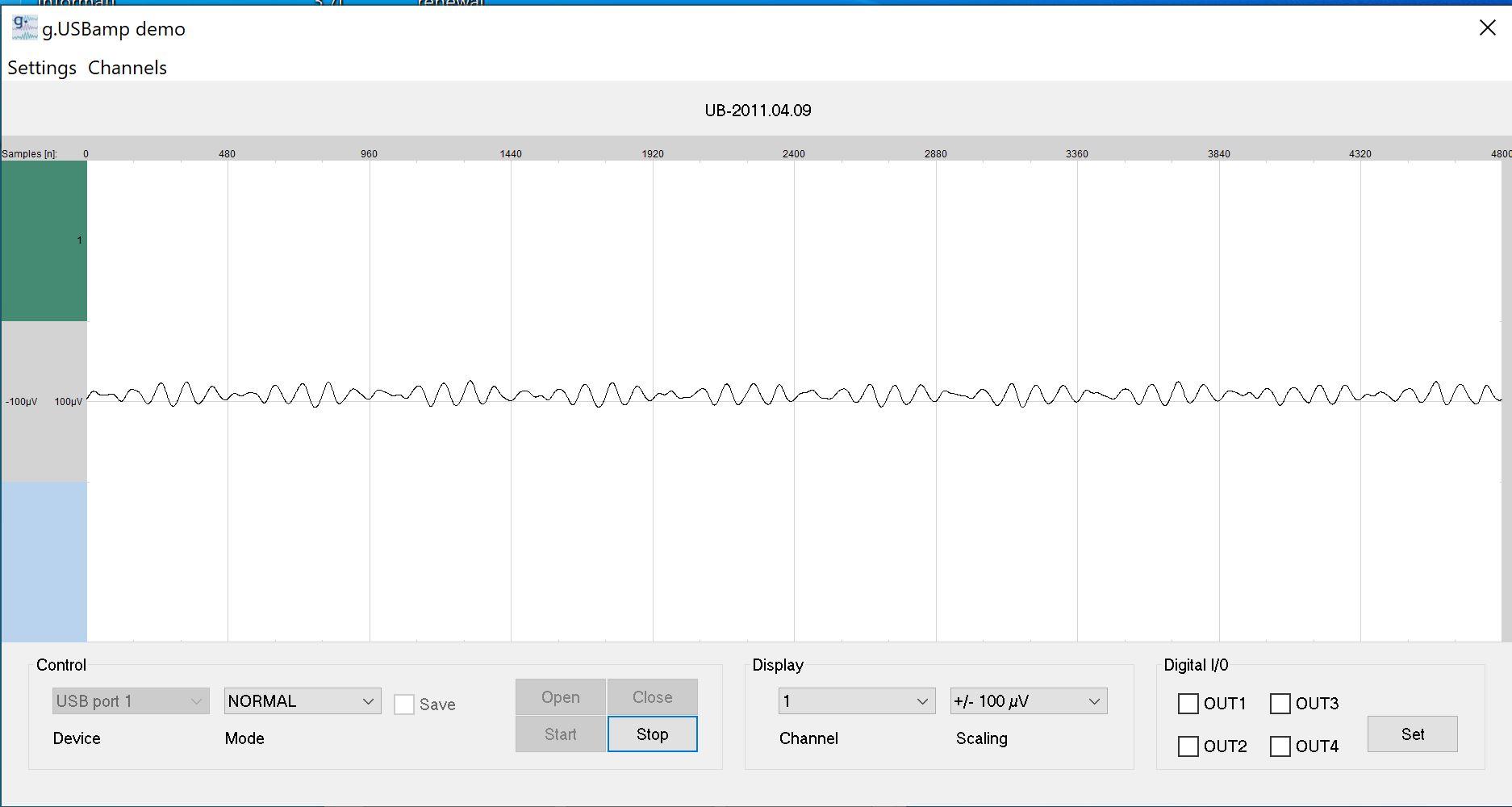
2067023-0

The following with 100Hz bandwidth in the USBamp app with Notch Filter on:
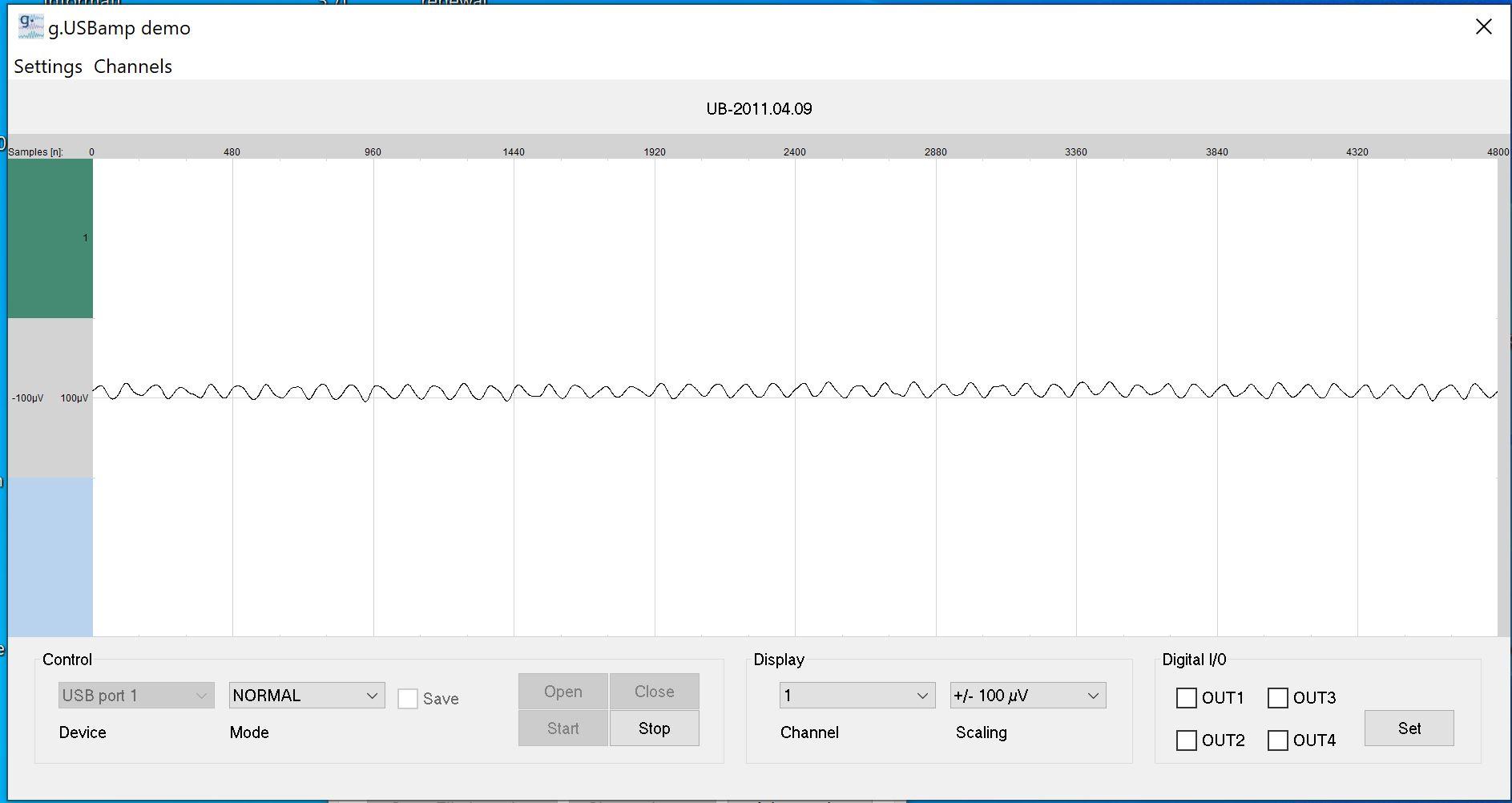
2066981-1

The following with 250Hz bandwidth in the USBamp app with Notch Filter off:
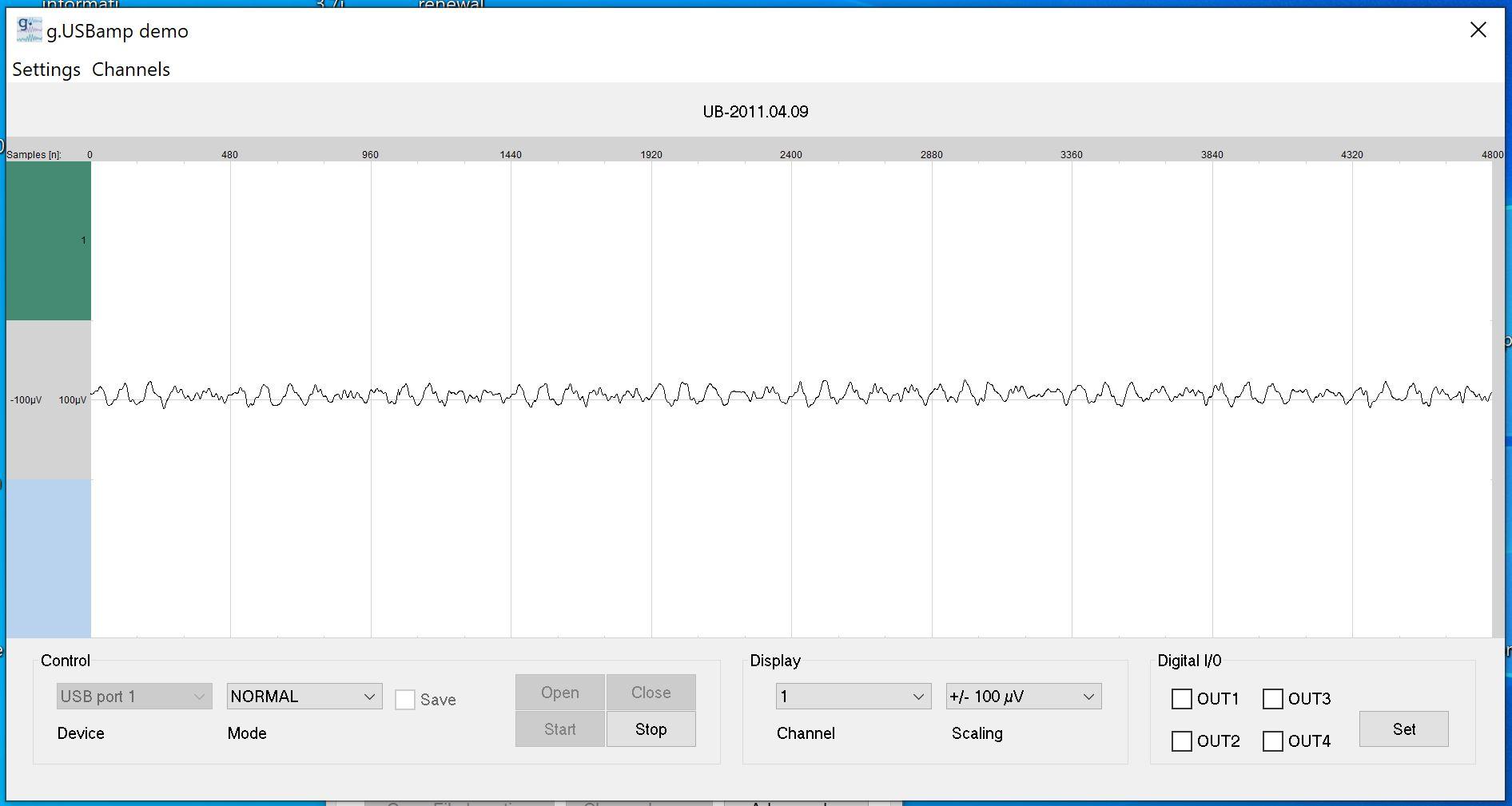
2066987-2

The following with 250Hz bandwidth in the USBamp app with Notch Filter on:
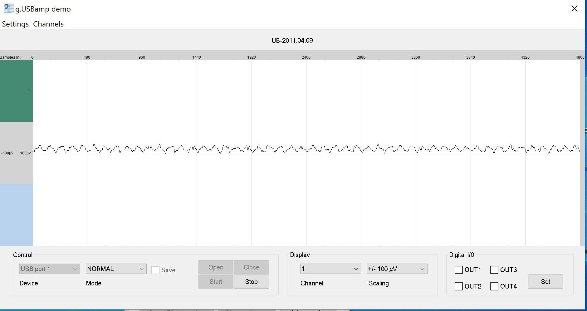
2066993-3

The following with 500Hz bandwidth in the USBamp app with Notch Filter off:
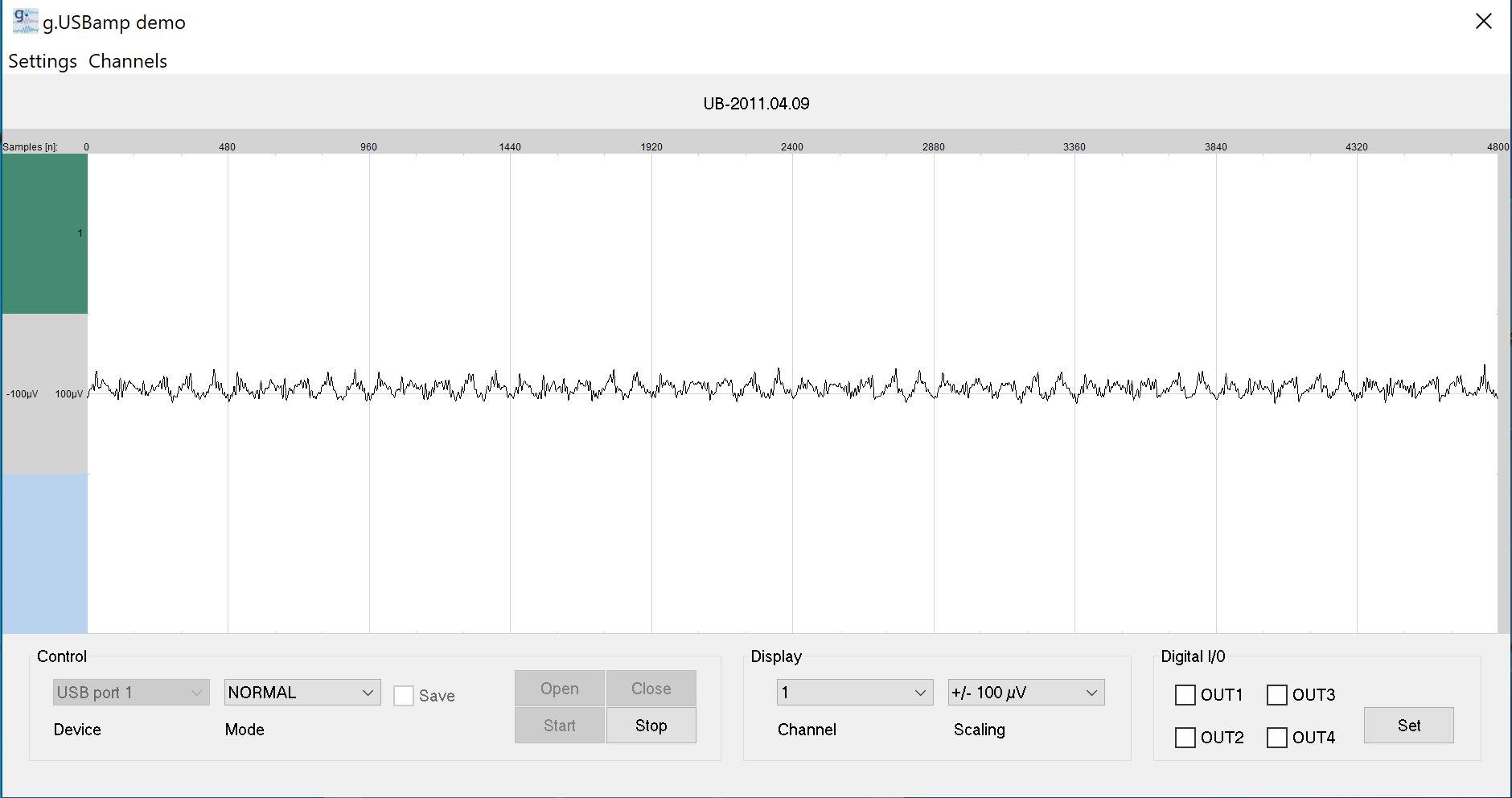
2066999-4

The following with 500Hz bandwidth in the USBamp app with Notch Filter on:
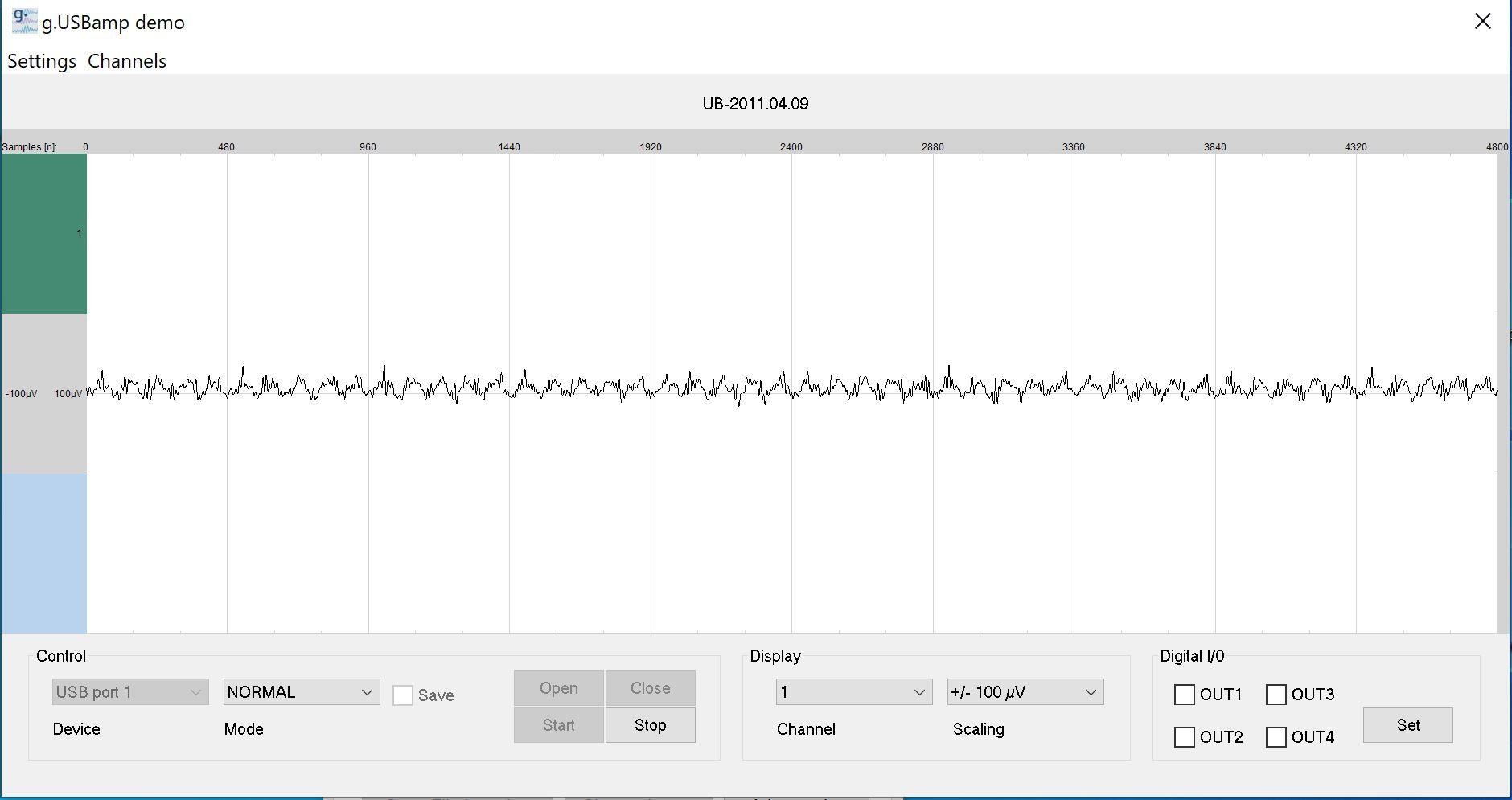
2067005-5

The following with 1000Hz bandwidth in the USBamp app with Notch Filter off:
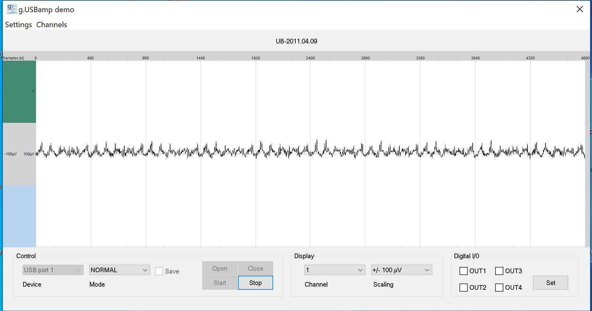
2067011-6

The following with 1000Hz bandwidth in the USBamp app with Notch Filter on:
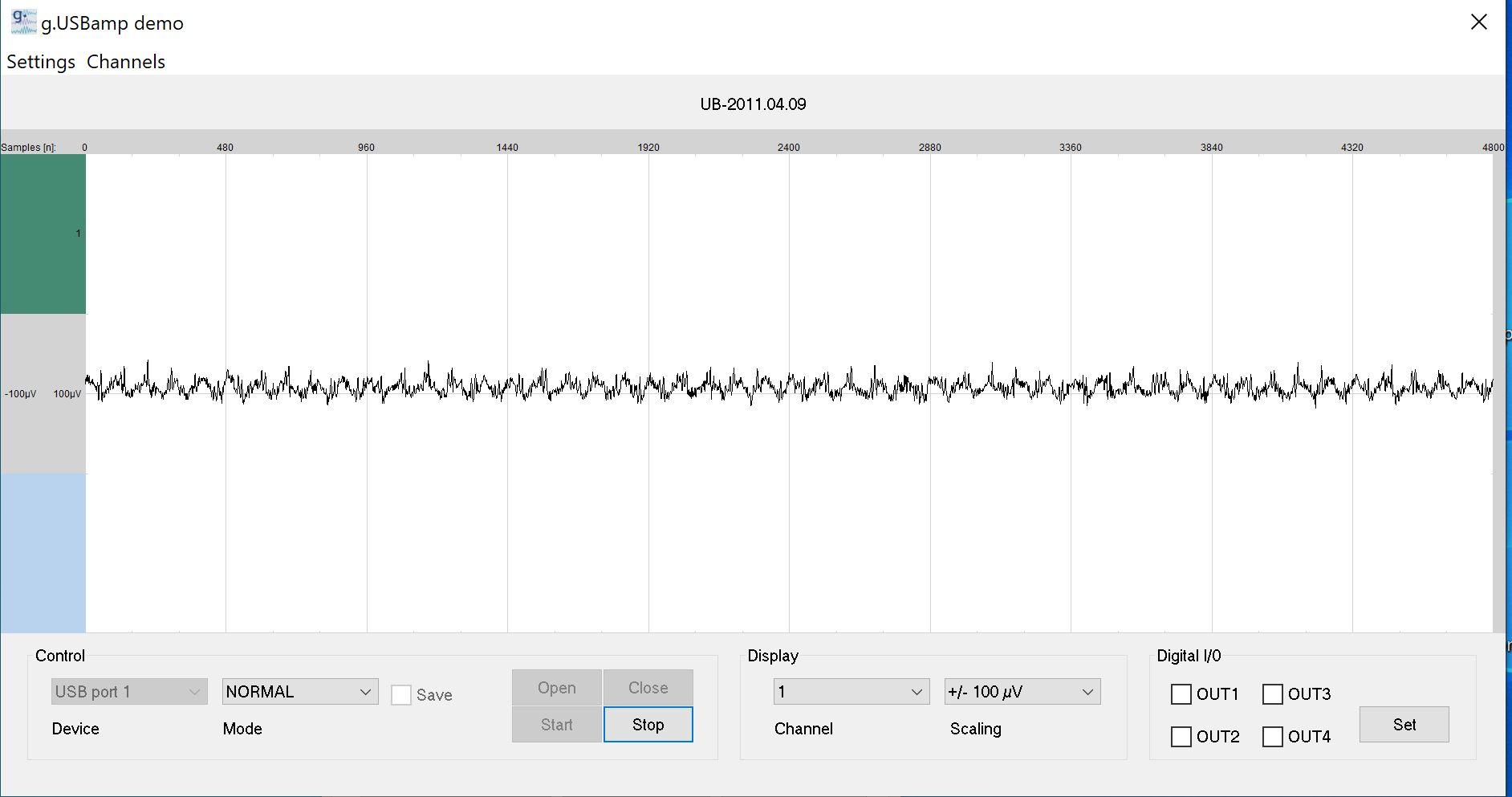
2067017-7


I shared all of them because I want to ask whether it is possible to use 1000Hz bandwidth in USBamp with 10uV input. The main unit may not be capable of it. No problem understanding/accepting this. But what I want to know is if you use active electrodes. Would the noise be any less at 1000Hz bandwidth? I read the gtec active electrodes have gain between 1 to 10. If 10 is chosen. And supposed the USBamp +- 250mV uses no gain. Does it mean the 10uV would become 100uV in the ADC +-250mV range? But how does it remove the noise at 10uV at 1000Hz bandwidth? I mean. I have 2 units of the BMA-200. It won't make the noise lesser than 5 nV/sqrt (Hz) for either.  So for the USBamp 400uV noise at 1-30Hz. How would it improve the noise at 10uV, 1000Hz bandwidth (or lesser) if 10X gain preamplifier in the active electrodes are used? I wanted to ask this for many days so anyone reading this please share what you think. Thanks.
 

Online Kleinstein

  • Super Contributor
  • ***
  • Posts: 14210
  • Country: de
Re: Instrumentation Amplifier Modification or Replacement
« Reply #90 on: March 12, 2024, 12:52:07 pm »
An active lectrode with gain could improve on the noise. The noise contribution from the later unit gets reduced by the gain (e.g. 10 x), but the noise of the active electrode is added. If the noise of the active electrodes is lower it can inporve things, if not it can also make things worse.

With the higher bandwidth the signal naturally looks more noisy. The noise is still only a small fraction of the dynamic range and thus not hindering recoding the data. The higher frequency noise can always be removed later, digital or by an eye trained to ignaore it. The question is not if one can use the higher BW, the question is only if it makes sense and gives more information with a more complex signal. Here it depends on what one wants to see from the signal, whether it makes sense to do it. So does the higher BW give really more information ? This is more a medical question not an electronc one.
 

Offline loop123Topic starter

  • Frequent Contributor
  • **
  • !
  • Posts: 297
  • Country: ca
Re: Instrumentation Amplifier Modification or Replacement
« Reply #91 on: March 12, 2024, 02:23:28 pm »
An active lectrode with gain could improve on the noise. The noise contribution from the later unit gets reduced by the gain (e.g. 10 x), but the noise of the active electrode is added. If the noise of the active electrodes is lower it can inporve things, if not it can also make things worse.

With the higher bandwidth the signal naturally looks more noisy. The noise is still only a small fraction of the dynamic range and thus not hindering recoding the data. The higher frequency noise can always be removed later, digital or by an eye trained to ignaore it. The question is not if one can use the higher BW, the question is only if it makes sense and gives more information with a more complex signal. Here it depends on what one wants to see from the signal, whether it makes sense to do it. So does the higher BW give really more information ? This is more a medical question not an electronc one.

How does this "The noise is still only a small fraction of the dynamic range and thus not hindering recoding the data" in ADCs compared to pure Op-amps, INA? Are you saying the noise in ADCs can be removed more easily than in analog Op-amps? Because let's say you have noise of 0.158uV in the Instrumentation Amplifier. If your signal is 0.3uV. It's none resolvable anymore. How does this compare to ADCs with its concept of dynamic range. Somehow you can still resolve 0.3uV even if  your noise is 0.158uV?
 

Online Kleinstein

  • Super Contributor
  • ***
  • Posts: 14210
  • Country: de
Re: Instrumentation Amplifier Modification or Replacement
« Reply #92 on: March 12, 2024, 05:09:25 pm »
The ADC has sufficient resolution and thus dynamic range, so that the noise alone is not filling much of the useful range. So it does not matter if one does the recording with a higher bandwidth and remove the noise by digital filtering later. So the question if one can record the data with 1 kHz or even a slightly higher BW (like 20 kHz) is not limited by the ADC, but by the way one wants to look at the data and how much S/N is needed for this.

The dynamic range can limit how much amplification one can have before the ADC. With the modern high resolution ADCs this is usually no longer an issue. E.g. the noise would still be way small than the 250 mV range of the ADC. It is more hum or similar background (more lower frequencies) that may have the largest amplitude and may limit the maximum gain.
The noise of the ADC is not fundamentally different from the amplifier noise, one just has the option to have before the ADC to make the ADC noise less important. The most critical part is usually the first part  (or the source itself) and this is naturally some amplifier.

It really depends on the effective BW that is used to look at the data. Methods like FFT can be quite effective in reducing the effective bandwidth and this way still get usible information from data the look like just noise to the eye. So it depends on the required S/N on what signal level is still OK. If the signal of interest is known well and long enough recording is possibe, really tiny signals con be recovered.
With the EEG one may not go down very much in the BW, but the signal from multiple electrodes may be combined, improving the S/N ration this way. Some 20 electrodes could give another 10 dB or so of S/N improvement.
 

Offline loop123Topic starter

  • Frequent Contributor
  • **
  • !
  • Posts: 297
  • Country: ca
Re: Instrumentation Amplifier Modification or Replacement
« Reply #93 on: March 12, 2024, 10:50:37 pm »
The ADC has sufficient resolution and thus dynamic range, so that the noise alone is not filling much of the useful range. So it does not matter if one does the recording with a higher bandwidth and remove the noise by digital filtering later. So the question if one can record the data with 1 kHz or even a slightly higher BW (like 20 kHz) is not limited by the ADC, but by the way one wants to look at the data and how much S/N is needed for this.

The dynamic range can limit how much amplification one can have before the ADC. With the modern high resolution ADCs this is usually no longer an issue. E.g. the noise would still be way small than the 250 mV range of the ADC. It is more hum or similar background (more lower frequencies) that may have the largest amplitude and may limit the maximum gain.
The noise of the ADC is not fundamentally different from the amplifier noise, one just has the option to have before the ADC to make the ADC noise less important. The most critical part is usually the first part  (or the source itself) and this is naturally some amplifier.

It really depends on the effective BW that is used to look at the data. Methods like FFT can be quite effective in reducing the effective bandwidth and this way still get usible information from data the look like just noise to the eye. So it depends on the required S/N on what signal level is still OK. If the signal of interest is known well and long enough recording is possibe, really tiny signals con be recovered.
With the EEG one may not go down very much in the BW, but the signal from multiple electrodes may be combined, improving the S/N ration this way. Some 20 electrodes could give another 10 dB or so of S/N improvement.


Is this comment about ADC also valid for the pure analog BMA-200 connected to the world best audio ADC, the E1DA ADC? I bought this ADC because someone recommended it as the best ADC ever made and its only purpose is not to let one hear music like the Focusrite but to analyze noises of components.

How does the BMA + E1DA ADC differ to the USBamp which doesn't use any amplifier but only the +-250mV ADC with 87.5nV sensitivity or the spec described: "Sensitivity   85,7 nV / +/- 250 mV" in your analysis above?

Is your description somehow only valid for the USBamp method of acquiring data which doesn't rely on high gain amplifier, like the 50000 gain I used on the BMA to make the 10uV appear as 0.5V?

Anyway the following is the BMA with 1000Hz Bandwidth acquiring the 10uV input. I still don't know if the noise is caused by EMI or something wrong with the amplifier. Please compare this to the noise of the USBamp at 1000Hz too below. Which has better signal to noise ratio? The $800 Netech EEG simulator is used to produce 10uV. It has clean 10uV so the following is not due to the Netech but either EMI noise or in the circuit itself.

BMA 10uV 1000Hz

2068022-0

$16750 USBamp 10uV 1000Hz

2068028-1


« Last Edit: March 15, 2024, 11:30:48 pm by loop123 »
 

Online Kleinstein

  • Super Contributor
  • ***
  • Posts: 14210
  • Country: de
Re: Instrumentation Amplifier Modification or Replacement
« Reply #94 on: March 13, 2024, 02:15:23 pm »
It is a bit hard to compare due to the poor scaling of the USBamp graph, bit it looks like the noise is smaller with the BMA + E1DA. From the data provided / parts used this is also expected.
It could well be that much is really noise from the amplifier and source resistor itself. One would have to look at the numbers (e.g. what RMS values in a band like 100 Hz to 500 Hz) to see if the noise level is what is expected, or if there is more (e.g. interference).
 

Offline loop123Topic starter

  • Frequent Contributor
  • **
  • !
  • Posts: 297
  • Country: ca
Re: Instrumentation Amplifier Modification or Replacement
« Reply #95 on: March 28, 2024, 10:13:26 pm »
It is a bit hard to compare due to the poor scaling of the USBamp graph, bit it looks like the noise is smaller with the BMA + E1DA. From the data provided / parts used this is also expected.
It could well be that much is really noise from the amplifier and source resistor itself. One would have to look at the numbers (e.g. what RMS values in a band like 100 Hz to 500 Hz) to see if the noise level is what is expected, or if there is more (e.g. interference).

I know noises in the resistors in the electrodes and leads can be higher than the amplifer itself. But still one wants the finest measuring device. I just heard of the incredible INA849 with ultra low noise of only 1nV/Sqrt (Hz)!  If i'll rewire the socket holder of my AMP01. Can I just replace it with the INA849 and still use the OPA2132P or must the buffer be another class and what is it? Or is the INA849 totally incompatible with the BMA AMP01 as replacement that one must design the INA849 from scratch? But without pcb and using breadboards, there would be so much noises and loose connections.

https://www.ti.com/lit/ds/symlink/ina849.pdf?ts=1711521697779&ref_url=https%253A%252F%252Fwww.ti.com%252Fproduct%252Fko-kr%252FINA849%253Futm_source%253Dgoogle%2526utm_medium%253Dcpc%2526utm_campaign%253Dasc-amps-null-44700045336317602_prodfolderdynamic-cpc-pf-google-kr_int%2526utm_content%253Dprodfolddynamic%2526ds_k%253DDYNAMIC+SEARCH+ADS%2526DCM%253Dyes%2526gad_source%253D1%2526gclid%253DCjwKCAjw5ImwBhBtEiwAFHDZx-CbS83Ti5H7tOkW_oybdo8x_HKRSLoZt73rlBjuDRlEqMqDPv5OHxoCfuIQAvD_BwE%2526gclsrc%253Daw.ds

2088098-0


Share me

Digg  Facebook  SlashDot  Delicious  Technorati  Twitter  Google  Yahoo
Smf