Author Topic: Instrumentation Amplifier Modification or Replacement  (Read 21707 times)

0 Members and 1 Guest are viewing this topic.

Offline loop123Topic starter

  • Frequent Contributor
  • **
  • !
  • Posts: 297
  • Country: ca
Re: Instrumentation Amplifier Modification or Replacement
« Reply #75 on: March 08, 2024, 08:39:48 am »
The noise from the resistor is 581 nV rms, not nv/sqrt(Hz). The noise from the resistor and amplifier add geometrical. So as sqrt(581²+158²), not as a direct sum.

Another part to add is the current noise multiplied with the source resistance. So some 0.15 pA/sqrt(Hz) * 20 K = 3 nV/sqrt(Hz). It is not that bad with 20 K , but it would with 500 K.

The EEG simulator should give a defined voltage. The ratio of the amplitude after the amplifier to the give votlage for the source is the gain factor for the amplifier. One can than divider the signal seen as noise by the gain to get the amplitude to the noise as voltage and not just output units.  It is well possible that the amplifier already has a defined gain and does the conversion with it's nominal gain. Usually that would be good enough for the noise testing.

2057420-0

Above I was testing the 20kohm resistor using the leads connected to the V+ and V- of the BSA AMP01, where am I supposed to connect the ground shown in green connected to the common in the input?

Say, in amplifiers. Does it make (V+ - ground) minus (V-  - ground) to come out with the differential signal? So if ground is some other value, the output signal would be some other value. Or does it make V+ minus V- and output it without regards to what is in the ground (or ref)?

When I used the 20kohm in the testing. Does it approximate the 20kohm impedance to skin usually encountered?  So the noise you see in the display is the same as the noise introduced by the 20kohm electrode to skin impedance?
 

Online Kleinstein

  • Super Contributor
  • ***
  • Posts: 14210
  • Country: de
Re: Instrumentation Amplifier Modification or Replacement
« Reply #76 on: March 08, 2024, 09:33:49 am »
The 20 K would be similar to the effect of 20 K electrode/skin resistance. For the ground connection one would need one, but ideally it does not make a difference if the ground is connected to the + or - input.
To get a bit closer to real life one could have another 20 K ohm in the ground connection.
 

Offline loop123Topic starter

  • Frequent Contributor
  • **
  • !
  • Posts: 297
  • Country: ca
Re: Instrumentation Amplifier Modification or Replacement
« Reply #77 on: March 08, 2024, 09:53:56 am »
The 20 K would be similar to the effect of 20 K electrode/skin resistance. For the ground connection one would need one, but ideally it does not make a difference if the ground is connected to the + or - input.
To get a bit closer to real life one could have another 20 K ohm in the ground connection.

You mean put a 20 k ohm between the ground lead and any of the + or - input already connected to another 20 k ohm resistor (as shown in photo)?


Btw... just wanna ask quick about the USBamp. It has this specs as shared before:

https://www.gtec.at/product/gusbamp-research/

Sensitivity   85.7 nV / +/- 250 mV
Amplifier type   real DC coupled
16 × ADC   24 Bit (38.4 kHz internal sampling per channel)
2 x DAC   12 bit
Noise level   < 0.4 µV rms 1-30 Hz

Let's say the noise at 1 - 30 Hz is 0.4uV rms. Then is even if it has sensitivity of 85.7 nV.  But you can't see below the noise of 0.4uV rms? then what is the use of the 85.7 nV sensitivity (same as resolution?)?
 

Online Kleinstein

  • Super Contributor
  • ***
  • Posts: 14210
  • Country: de
Re: Instrumentation Amplifier Modification or Replacement
« Reply #78 on: March 08, 2024, 10:49:42 am »
The 82.7 nV may be the LSB steps of the ADC. This would be a little more then 250 mV range with 24 bits, but there could well be some overrange with limited usabilty (would expect this and not complain about this). The 0.4 µV would than be the total noise - both from the ADC and amplifiers. The quantization noise due to the LSB size is only a very small farction of this ( step / sqrt(12)  and more than 30 Hz bandwidth).
One could see below 0.4 µV if the bandwidth is less than 30 Hz. It is also not clear how much of that noise is low frequency 1/f noise from the low end (e.g. 1 - 5 Hz). So things may be better with slightly higher frequencies. The other point could be some amplification at the front end.
 

Offline loop123Topic starter

  • Frequent Contributor
  • **
  • !
  • Posts: 297
  • Country: ca
Re: Instrumentation Amplifier Modification or Replacement
« Reply #79 on: March 09, 2024, 02:07:24 am »
I made a big mistake. In EEG system, the REF is the V-, while in EMG, the REF is the ground.
But in Netech EEG Simulator, their REF is not the V- but the ground. In electronics, do you refer to REF as V- or the ground?

2058992-0

2058998-1

So since February 15. I connected the AMP01 V- to the Netech REF/Ground. And the AMP01 ground to the V- output of Netech. This produced a signal that is 10 times stronger! With that corrected. the following is the waveform at 10 microvolt at 100 Hz. Is the non-uniform amplitudes due to the signal 10uV less than the input offset voltage?

2059004-2

With the bandwidth set to 1000Hz. The following is the output at 10uV. It's unrecognizable. For noise of 0.158 uV. Can it cause such distortion for the 10uV signal? Or is this cause by the infamous intereference current? What do you guys think?

2059010-3

Only when it is set to stronger 30 microvolt 100Hz that the amplitudes are uniform.

2059016-4

Give me something to replace the AMP01 which can make it good enough at 1000Hz bandwidth at 10uV. (btw.. how do you write micro symbol here?)
 

Offline Terry Bites

  • Super Contributor
  • ***
  • Posts: 2393
  • Country: gb
  • Recovering Electrical Engineer
Re: Instrumentation Amplifier Modification or Replacement
« Reply #80 on: March 09, 2024, 10:00:56 am »
Active electrodes massively reduce the source.  In.Rs contributes very little to the total INA noise. A low noise bipolar INA is ideal.
Consider using an ultra low noise (low cost) audio amp eg THAT1580. BTW the That guys are incredibly helpful.
https://thatcorp.com/low-noise-preamplifier-ics/
Also see LT1115 DS applictions.


Offline loop123Topic starter

  • Frequent Contributor
  • **
  • !
  • Posts: 297
  • Country: ca
Re: Instrumentation Amplifier Modification or Replacement
« Reply #81 on: March 09, 2024, 12:46:26 pm »
Active electrodes massively reduce the source.  In.Rs contributes very little to the total INA noise. A low noise bipolar INA is ideal.
Consider using an ultra low noise (low cost) audio amp eg THAT1580. BTW the That guys are incredibly helpful.
https://thatcorp.com/low-noise-preamplifier-ics/
Also see LT1115 DS applictions.

K.L Einstein (a relative?) hates active electrodes and his words carry weight.

Also with the Netech EEG rightly connected. The $16750 g.USBamp has very noisy 10uV at 1000hz bandwidth  that is unrecognizable. And their technical support couldnt answer the gain of their top actives which sells $2000 for just one lead and driver box. And there is no active electrodes available generically. One has to build one custom for the main amp.

About THAT1580. I already have the E1DA Cosmos APU with THAT1510 but it is only 36dB and 60dB. no way to adjust. I used the E1DA Cosmos ADC as main ADC. Someone said it is the best ADC in the world.

Btw how does one test the output impedance of the BMA200? The Cosmos ADC has small input impedance so today I realized if they are match. But I have the E1DA Scaler for impedance converter which ill try this weekend.
« Last Edit: March 10, 2024, 03:24:10 am by loop123 »
 

Online Kleinstein

  • Super Contributor
  • ***
  • Posts: 14210
  • Country: de
Re: Instrumentation Amplifier Modification or Replacement
« Reply #82 on: March 09, 2024, 02:29:19 pm »
The LT1115 is a very low voltage noise amplifier, but is rather high current noise and thus not suited for electrodes with a source impedance.
The THAT1580 has a current noise of some 1.5 pA/sqrt(Hz) - and likely more at t low frequency. With a 20 Kohm electrode this converts to 30 nV/sqrt(Hz) - so no longer low noise.
These low noise audio amplifier are made for low impedance (< 200 ohm) signal sources.

The active electrodes are not all bad, but I see little to no advantage compared to a shielded cable. Noise wise there is no real need for super low noise after the active electrode, that has already added noise.
So having an active probe in front still does not need a super low noise amplifier for low impedance.

Good amplifier have so little noise that the source resistance is the major noise source. So there is no need to get the absolute lowest noise amplifier - this makes rather little difference. A bad choice (like one with high current noise) can still ruin the day.

The specs / information for the USBamp are a bit confusing. The noise specs look not impressive when used without extra gain in front.  It could still be sufficient, if there is additional noise / interference from the biological side / environment.
 

Offline loop123Topic starter

  • Frequent Contributor
  • **
  • !
  • Posts: 297
  • Country: ca
Re: Instrumentation Amplifier Modification or Replacement
« Reply #83 on: March 09, 2024, 04:10:08 pm »
2060399-0

2060405-1


Even after I used the E1DA Scaler for impedance match, still no help as the 10 microVolt signal is still distorted. I unplugged the extension cord in the photo.

I tried to fit the Netech and connector box (I took out the ISO-Z pcb) in a small Faraday Cage box for cellphone, but it won't fit.

I will try to look for bigger metal container for biscuit to fit them. It will serve as Faraday Cage right? or does the all meter container need more thickness?

I'm still waiting for the shielded leads. Last result. Big size Faraday Cage.
 

Online Kleinstein

  • Super Contributor
  • ***
  • Posts: 14210
  • Country: de
Re: Instrumentation Amplifier Modification or Replacement
« Reply #84 on: March 09, 2024, 07:37:02 pm »
For shielding the electric field it only needs a rather thin metal thickness, especially at low frequencies. So the biscuit box should be OK. For shilding a magnetic field, more thickness may be better. Here a relatively thin wall may get quite some field (AC and earths field) as it concentrates the field from quite some volume.

The signal looks a bit like a superposition of 50 Hz and 60 Hz. One may get it separated in a FFT and see if there are other frequencies included too.
 

Offline loop123Topic starter

  • Frequent Contributor
  • **
  • !
  • Posts: 297
  • Country: ca
Re: Instrumentation Amplifier Modification or Replacement
« Reply #85 on: March 10, 2024, 05:06:32 am »
For shielding the electric field it only needs a rather thin metal thickness, especially at low frequencies. So the biscuit box should be OK. For shilding a magnetic field, more thickness may be better. Here a relatively thin wall may get quite some field (AC and earths field) as it concentrates the field from quite some volume.

The signal looks a bit like a superposition of 50 Hz and 60 Hz. One may get it separated in a FFT and see if there are other frequencies included too.

The BMA unit has BNC output at the back where the direct voltage output/signal is directly fed to the ADC and into Audacity.   How do you get an FFT to read the direct voltage file (what term is this called?)  Also how can I make EEGLab in Matlab read and analyze the frequency spectrum of the file? What format must I export it at Audacity to make it compatible with Matlab and EEGLab? Or is this impossible to do?


Offline loop123Topic starter

  • Frequent Contributor
  • **
  • !
  • Posts: 297
  • Country: ca
Re: Instrumentation Amplifier Modification or Replacement
« Reply #86 on: March 10, 2024, 09:27:28 am »
I put the Netech and connector box inside a metal box, but there was no changes whatever to the waveforms, why?? Here is before the metal box cover is put and the image after the metal is cover shut.

2062109-0

2062115-1


I made the hole the same size as the wire so there is no hole. But even if there is 0.00001" slit, the entire capacitive coupling field would enter it much like air entering a small hole? There is absolutely no improvement in the waveforms after they were put inside the metal box. This is the waveform before the cover was placed and after it was placed.

Before cover put. 10 microvolt 60Hz signal input (I tried 50Hz input too but the same waveforms). BMA has 100Hz bandwidth, 50000 gain selected.

2062121-2

After metal cover put and shut.

2062127-3

Absolutely no difference, why? If it is capacitive coupling from 60Hz. Should there be a decrease in the interference in the waveforms even if say the metal seal is not 100%? Can capacitive coupling currents diffuse like gas to slits much like a very tiny hole can have the entire gas sucked in in milliseconds?

If it is not capacitive coupling, could it be the circuit itself can't deal with 10 microVolt signal?  The wire from metal box to amplifier is shielded btw. Thanks.
 

Online Kleinstein

  • Super Contributor
  • ***
  • Posts: 14210
  • Country: de
Re: Instrumentation Amplifier Modification or Replacement
« Reply #87 on: March 10, 2024, 09:49:52 am »
Capacitive coupling at low frequency will not sneak through a small hole. That can happen with high frequencies (e.g. GHz range). To be an effective shild the case should be connected to the circuit ground however.

For the amplifier / ADC system there should be no lower limit that the system can't work with. It is just that the lower the signal the more important the noise gets. As a check for the noise and interference it also helps to set the signal to 0 amplitude (but still connect the source if possible). This would give the noise and background. One can usually expect the interference to be mainly additive, so the same level of interference also when the signal is there.

It is possible that background hum can come in at the amplifier itself, or at the EEG simulator. Another way is magnetic coupling, especially if there is a large area between the probe wires. For magnetic coupling the box can help, but it would not be perfect.
 

Offline loop123Topic starter

  • Frequent Contributor
  • **
  • !
  • Posts: 297
  • Country: ca
Re: Instrumentation Amplifier Modification or Replacement
« Reply #88 on: March 10, 2024, 10:19:24 am »
Capacitive coupling at low frequency will not sneak through a small hole. That can happen with high frequencies (e.g. GHz range). To be an effective shild the case should be connected to the circuit ground however.

For the amplifier / ADC system there should be no lower limit that the system can't work with. It is just that the lower the signal the more important the noise gets. As a check for the noise and interference it also helps to set the signal to 0 amplitude (but still connect the source if possible). This would give the noise and background. One can usually expect the interference to be mainly additive, so the same level of interference also when the signal is there.

It is possible that background hum can come in at the amplifier itself, or at the EEG simulator. Another way is magnetic coupling, especially if there is a large area between the probe wires. For magnetic coupling the box can help, but it would not be perfect.

The metal box is connected to the ground as you can see in the picture.

How do you set the signal to 0 amplitude. The Netech only has 10uV minimum and 0.5 Hz. At 0.5Hz, there is the same distortion.

I was asking earlier. The BMA unit has BNC output at the back where the direct voltage output/signal is directly fed to the ADC and into Audacity.   How do you get an FFT to read the direct voltage file (what term is this called?)  Also how can I make EEGLab in Matlab read and analyze the frequency spectrum of the file? What format must I export it at Audacity to make it compatible with Matlab and EEGLab? Or is this impossible to do?
 

Offline loop123Topic starter

  • Frequent Contributor
  • **
  • !
  • Posts: 297
  • Country: ca
Re: Instrumentation Amplifier Modification or Replacement
« Reply #89 on: March 12, 2024, 10:14:19 am »
Capacitive coupling at low frequency will not sneak through a small hole. That can happen with high frequencies (e.g. GHz range). To be an effective shild the case should be connected to the circuit ground however.

For the amplifier / ADC system there should be no lower limit that the system can't work with. It is just that the lower the signal the more important the noise gets. As a check for the noise and interference it also helps to set the signal to 0 amplitude (but still connect the source if possible). This would give the noise and background. One can usually expect the interference to be mainly additive, so the same level of interference also when the signal is there.

It is possible that background hum can come in at the amplifier itself, or at the EEG simulator. Another way is magnetic coupling, especially if there is a large area between the probe wires. For magnetic coupling the box can help, but it would not be perfect.

I first learnt the Netech simulator was not wired correctly when I tried to run the $16750 USBamp demo program (which limits it to 4800Hz sampling frequency and 60,100,250,500,1000,2000Hz bandwidth) and saw the scaling was not correct). Demo because I still don't know if the $4000 software is worth it. The USBamp is used by hundreds of many big companies and large R&D centers. They have many researched papers and I want to verify whether it is even possible to use 1000Hz bandwidth to sample a 10uV input.

The following are the outputs from USBamp demo (offset is adjusted to 100uV or it can go off the scale).
The Netech EEG simulator has identical 10uV, 50Hz input in all waveforms. I chose 50Hz because the frequency in the Netech is only 0.1Hz, 2Hz, 5Hz, 50Hz, 60Hz. I didn't chose 60Hz because applying the brick wall 60Hz notch filter at USBamp demo will null all amplitudes.

The following is the USBamp set to 100Hz Bandwidth. I can't choose 30Hz because no amplitudes can be seen because the Netech simulator input frequency is 50Hz.


The following with 100Hz bandwidth in the USBamp app with Notch Filter off:
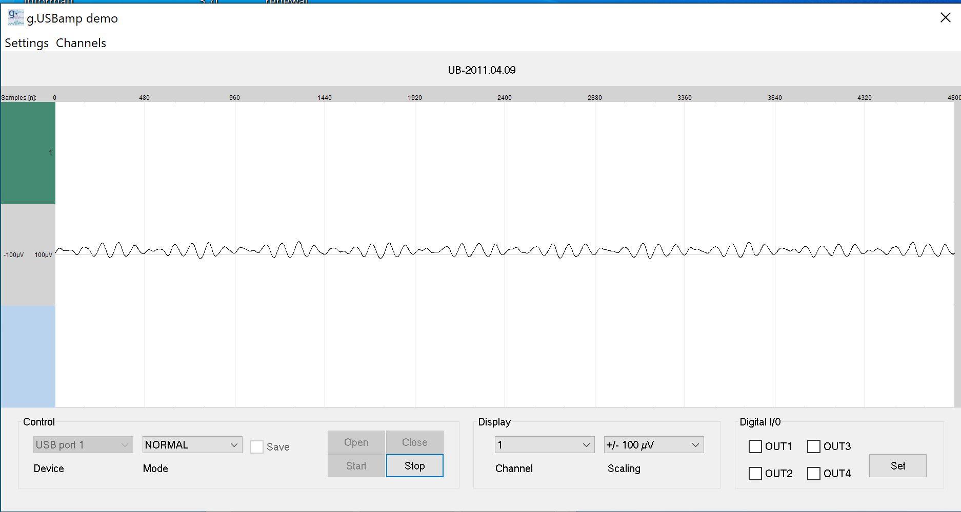
2067023-0

The following with 100Hz bandwidth in the USBamp app with Notch Filter on:
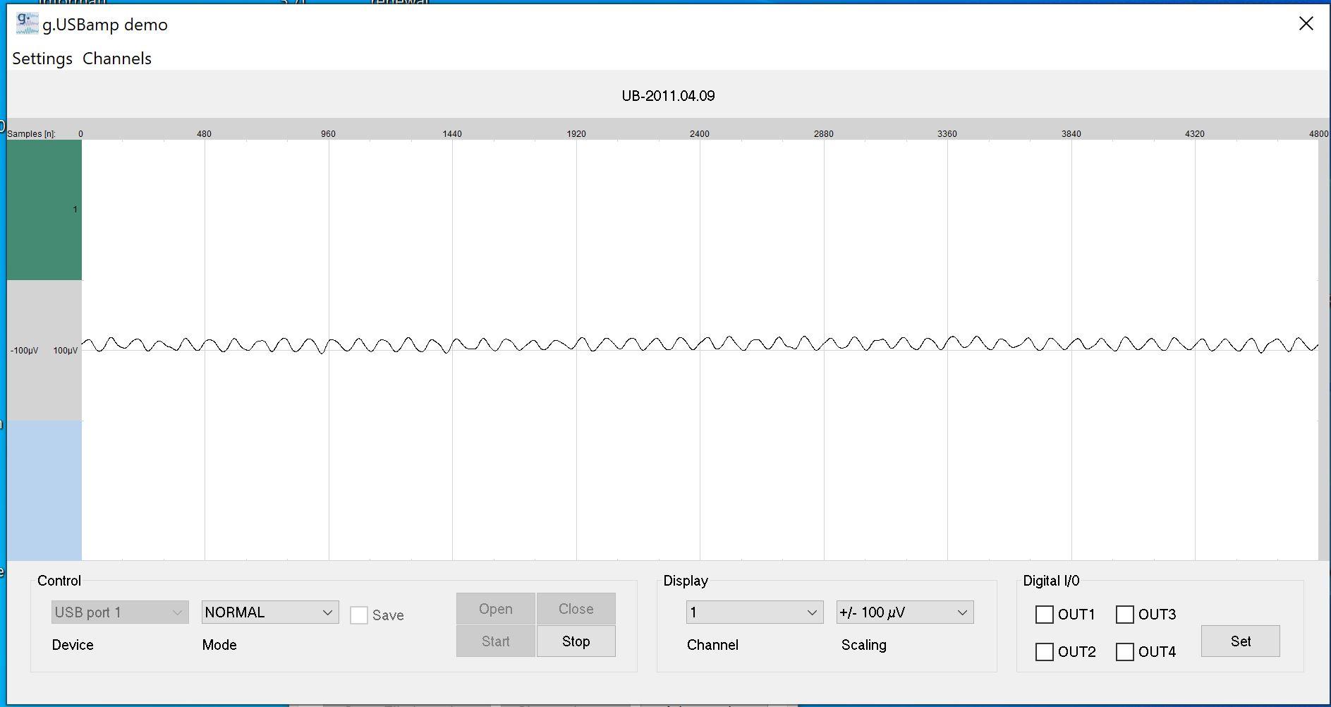
2066981-1

The following with 250Hz bandwidth in the USBamp app with Notch Filter off:
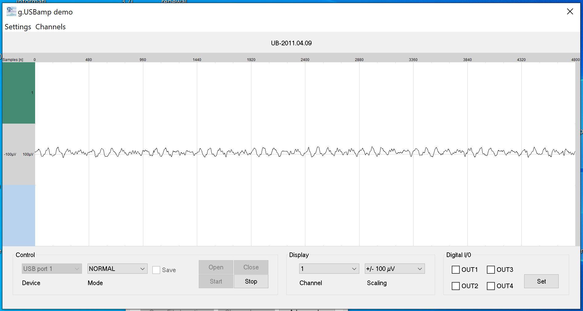
2066987-2

The following with 250Hz bandwidth in the USBamp app with Notch Filter on:
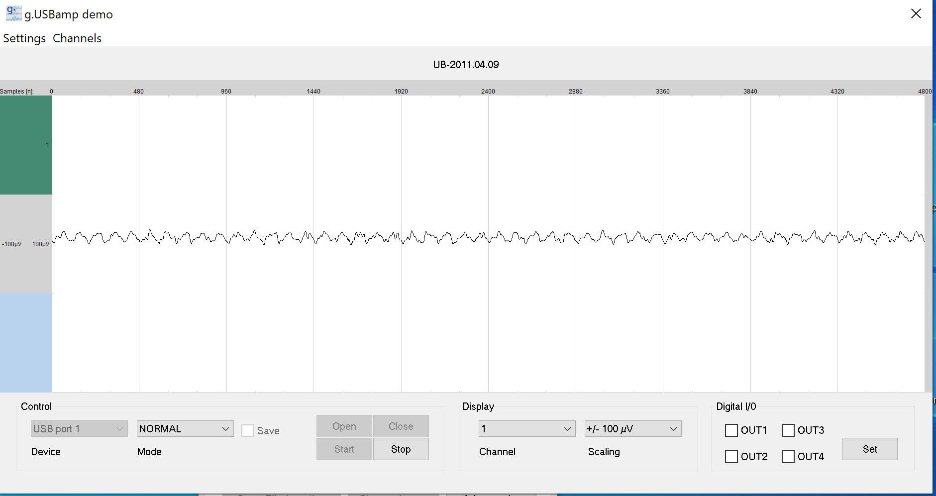
2066993-3

The following with 500Hz bandwidth in the USBamp app with Notch Filter off:
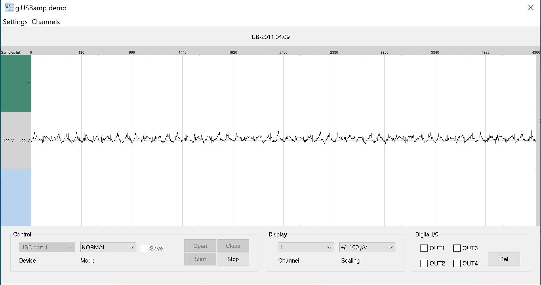
2066999-4

The following with 500Hz bandwidth in the USBamp app with Notch Filter on:
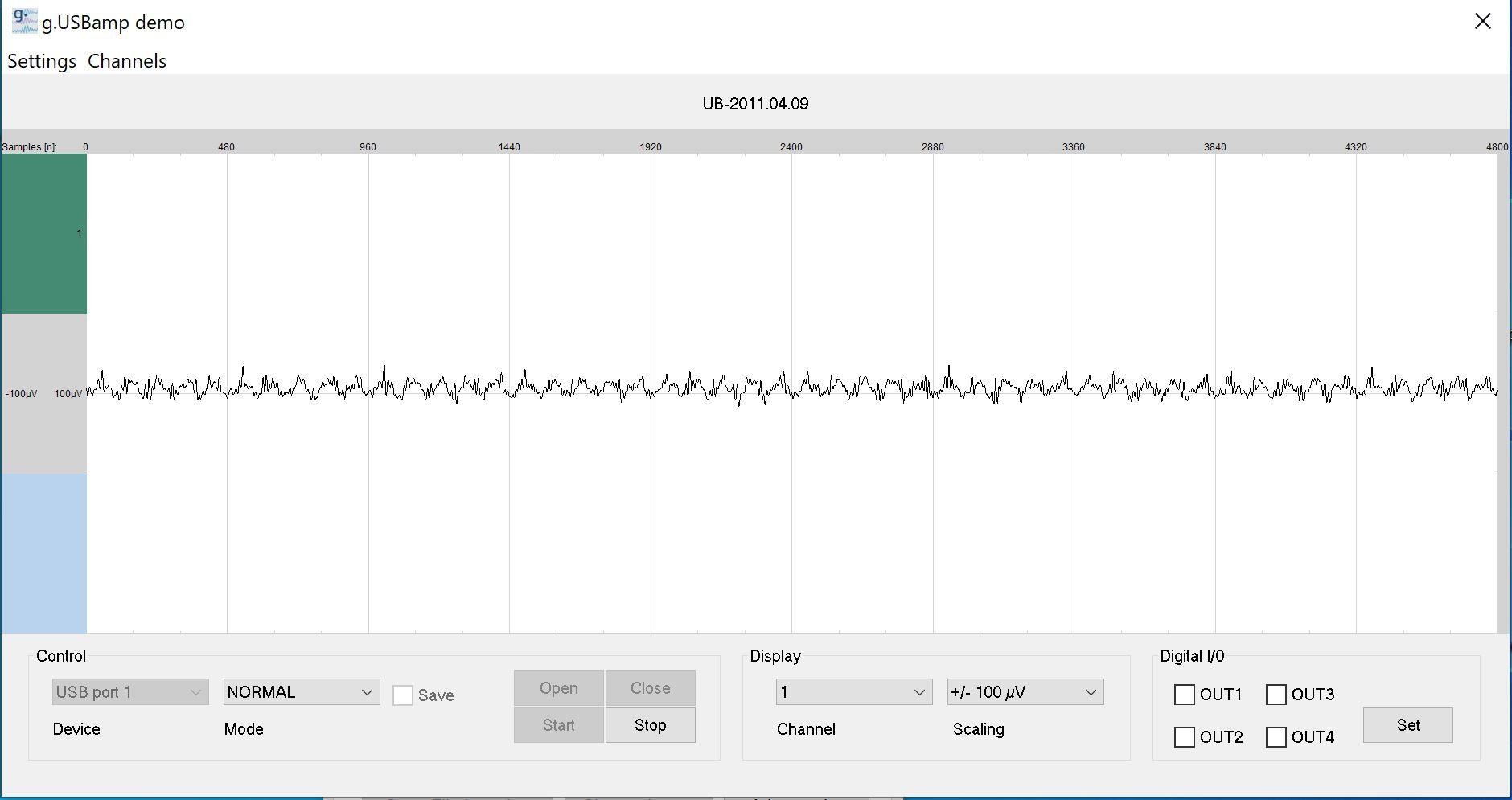
2067005-5

The following with 1000Hz bandwidth in the USBamp app with Notch Filter off:
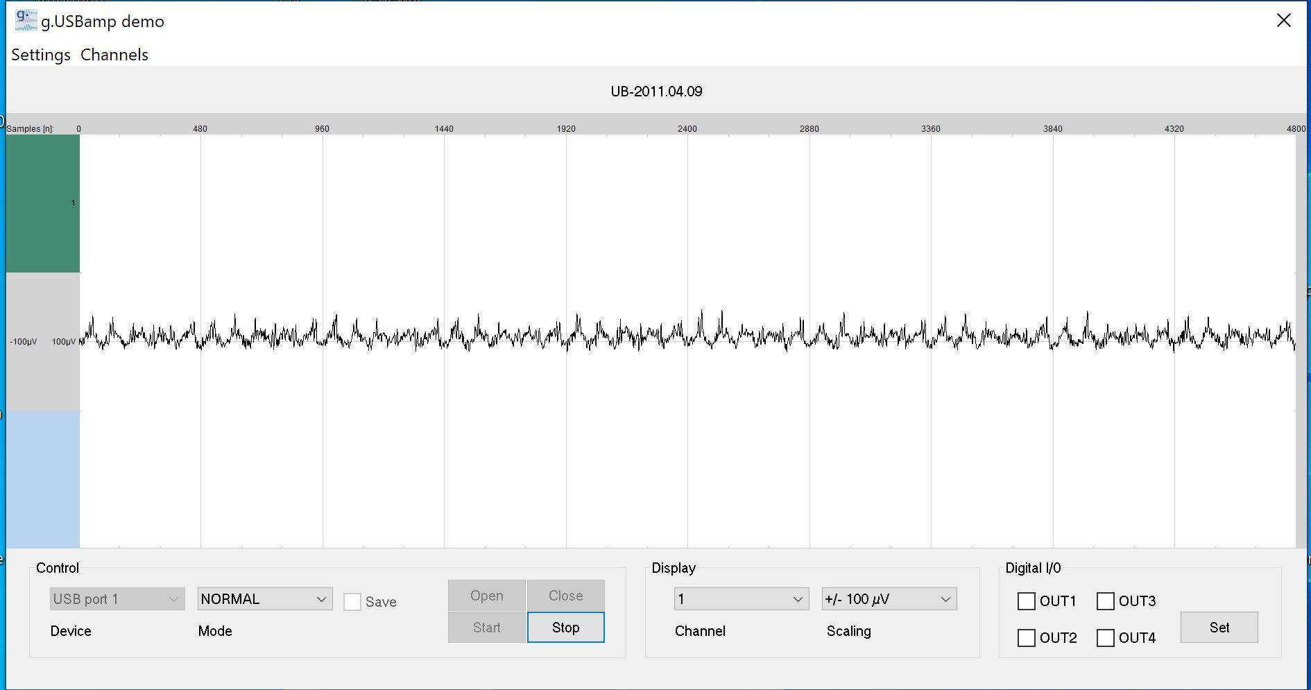
2067011-6

The following with 1000Hz bandwidth in the USBamp app with Notch Filter on:
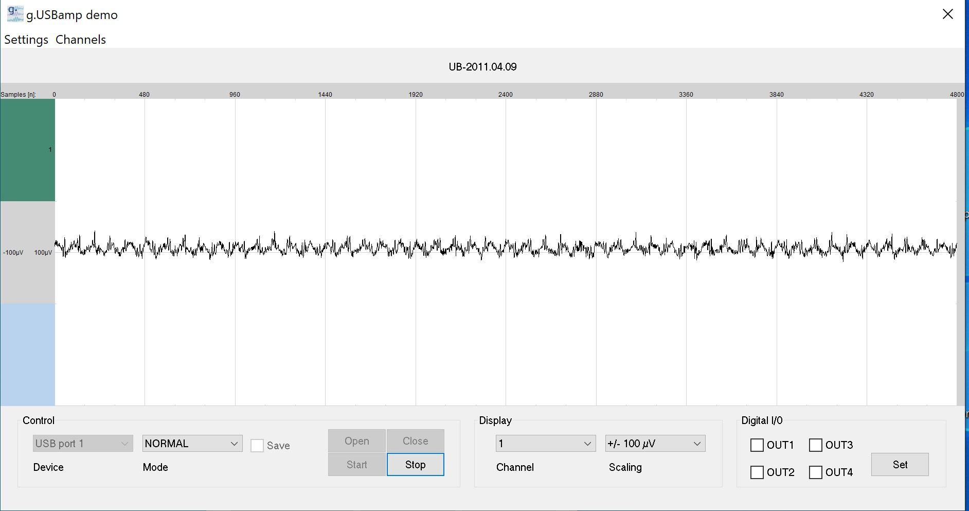
2067017-7


I shared all of them because I want to ask whether it is possible to use 1000Hz bandwidth in USBamp with 10uV input. The main unit may not be capable of it. No problem understanding/accepting this. But what I want to know is if you use active electrodes. Would the noise be any less at 1000Hz bandwidth? I read the gtec active electrodes have gain between 1 to 10. If 10 is chosen. And supposed the USBamp +- 250mV uses no gain. Does it mean the 10uV would become 100uV in the ADC +-250mV range? But how does it remove the noise at 10uV at 1000Hz bandwidth? I mean. I have 2 units of the BMA-200. It won't make the noise lesser than 5 nV/sqrt (Hz) for either.  So for the USBamp 400uV noise at 1-30Hz. How would it improve the noise at 10uV, 1000Hz bandwidth (or lesser) if 10X gain preamplifier in the active electrodes are used? I wanted to ask this for many days so anyone reading this please share what you think. Thanks.
 

Online Kleinstein

  • Super Contributor
  • ***
  • Posts: 14210
  • Country: de
Re: Instrumentation Amplifier Modification or Replacement
« Reply #90 on: March 12, 2024, 12:52:07 pm »
An active lectrode with gain could improve on the noise. The noise contribution from the later unit gets reduced by the gain (e.g. 10 x), but the noise of the active electrode is added. If the noise of the active electrodes is lower it can inporve things, if not it can also make things worse.

With the higher bandwidth the signal naturally looks more noisy. The noise is still only a small fraction of the dynamic range and thus not hindering recoding the data. The higher frequency noise can always be removed later, digital or by an eye trained to ignaore it. The question is not if one can use the higher BW, the question is only if it makes sense and gives more information with a more complex signal. Here it depends on what one wants to see from the signal, whether it makes sense to do it. So does the higher BW give really more information ? This is more a medical question not an electronc one.
 

Offline loop123Topic starter

  • Frequent Contributor
  • **
  • !
  • Posts: 297
  • Country: ca
Re: Instrumentation Amplifier Modification or Replacement
« Reply #91 on: March 12, 2024, 02:23:28 pm »
An active lectrode with gain could improve on the noise. The noise contribution from the later unit gets reduced by the gain (e.g. 10 x), but the noise of the active electrode is added. If the noise of the active electrodes is lower it can inporve things, if not it can also make things worse.

With the higher bandwidth the signal naturally looks more noisy. The noise is still only a small fraction of the dynamic range and thus not hindering recoding the data. The higher frequency noise can always be removed later, digital or by an eye trained to ignaore it. The question is not if one can use the higher BW, the question is only if it makes sense and gives more information with a more complex signal. Here it depends on what one wants to see from the signal, whether it makes sense to do it. So does the higher BW give really more information ? This is more a medical question not an electronc one.

How does this "The noise is still only a small fraction of the dynamic range and thus not hindering recoding the data" in ADCs compared to pure Op-amps, INA? Are you saying the noise in ADCs can be removed more easily than in analog Op-amps? Because let's say you have noise of 0.158uV in the Instrumentation Amplifier. If your signal is 0.3uV. It's none resolvable anymore. How does this compare to ADCs with its concept of dynamic range. Somehow you can still resolve 0.3uV even if  your noise is 0.158uV?
 

Online Kleinstein

  • Super Contributor
  • ***
  • Posts: 14210
  • Country: de
Re: Instrumentation Amplifier Modification or Replacement
« Reply #92 on: March 12, 2024, 05:09:25 pm »
The ADC has sufficient resolution and thus dynamic range, so that the noise alone is not filling much of the useful range. So it does not matter if one does the recording with a higher bandwidth and remove the noise by digital filtering later. So the question if one can record the data with 1 kHz or even a slightly higher BW (like 20 kHz) is not limited by the ADC, but by the way one wants to look at the data and how much S/N is needed for this.

The dynamic range can limit how much amplification one can have before the ADC. With the modern high resolution ADCs this is usually no longer an issue. E.g. the noise would still be way small than the 250 mV range of the ADC. It is more hum or similar background (more lower frequencies) that may have the largest amplitude and may limit the maximum gain.
The noise of the ADC is not fundamentally different from the amplifier noise, one just has the option to have before the ADC to make the ADC noise less important. The most critical part is usually the first part  (or the source itself) and this is naturally some amplifier.

It really depends on the effective BW that is used to look at the data. Methods like FFT can be quite effective in reducing the effective bandwidth and this way still get usible information from data the look like just noise to the eye. So it depends on the required S/N on what signal level is still OK. If the signal of interest is known well and long enough recording is possibe, really tiny signals con be recovered.
With the EEG one may not go down very much in the BW, but the signal from multiple electrodes may be combined, improving the S/N ration this way. Some 20 electrodes could give another 10 dB or so of S/N improvement.
 

Offline loop123Topic starter

  • Frequent Contributor
  • **
  • !
  • Posts: 297
  • Country: ca
Re: Instrumentation Amplifier Modification or Replacement
« Reply #93 on: March 12, 2024, 10:50:37 pm »
The ADC has sufficient resolution and thus dynamic range, so that the noise alone is not filling much of the useful range. So it does not matter if one does the recording with a higher bandwidth and remove the noise by digital filtering later. So the question if one can record the data with 1 kHz or even a slightly higher BW (like 20 kHz) is not limited by the ADC, but by the way one wants to look at the data and how much S/N is needed for this.

The dynamic range can limit how much amplification one can have before the ADC. With the modern high resolution ADCs this is usually no longer an issue. E.g. the noise would still be way small than the 250 mV range of the ADC. It is more hum or similar background (more lower frequencies) that may have the largest amplitude and may limit the maximum gain.
The noise of the ADC is not fundamentally different from the amplifier noise, one just has the option to have before the ADC to make the ADC noise less important. The most critical part is usually the first part  (or the source itself) and this is naturally some amplifier.

It really depends on the effective BW that is used to look at the data. Methods like FFT can be quite effective in reducing the effective bandwidth and this way still get usible information from data the look like just noise to the eye. So it depends on the required S/N on what signal level is still OK. If the signal of interest is known well and long enough recording is possibe, really tiny signals con be recovered.
With the EEG one may not go down very much in the BW, but the signal from multiple electrodes may be combined, improving the S/N ration this way. Some 20 electrodes could give another 10 dB or so of S/N improvement.


Is this comment about ADC also valid for the pure analog BMA-200 connected to the world best audio ADC, the E1DA ADC? I bought this ADC because someone recommended it as the best ADC ever made and its only purpose is not to let one hear music like the Focusrite but to analyze noises of components.

How does the BMA + E1DA ADC differ to the USBamp which doesn't use any amplifier but only the +-250mV ADC with 87.5nV sensitivity or the spec described: "Sensitivity   85,7 nV / +/- 250 mV" in your analysis above?

Is your description somehow only valid for the USBamp method of acquiring data which doesn't rely on high gain amplifier, like the 50000 gain I used on the BMA to make the 10uV appear as 0.5V?

Anyway the following is the BMA with 1000Hz Bandwidth acquiring the 10uV input. I still don't know if the noise is caused by EMI or something wrong with the amplifier. Please compare this to the noise of the USBamp at 1000Hz too below. Which has better signal to noise ratio? The $800 Netech EEG simulator is used to produce 10uV. It has clean 10uV so the following is not due to the Netech but either EMI noise or in the circuit itself.

BMA 10uV 1000Hz

2068022-0

$16750 USBamp 10uV 1000Hz

2068028-1


« Last Edit: March 15, 2024, 11:30:48 pm by loop123 »
 

Online Kleinstein

  • Super Contributor
  • ***
  • Posts: 14210
  • Country: de
Re: Instrumentation Amplifier Modification or Replacement
« Reply #94 on: March 13, 2024, 02:15:23 pm »
It is a bit hard to compare due to the poor scaling of the USBamp graph, bit it looks like the noise is smaller with the BMA + E1DA. From the data provided / parts used this is also expected.
It could well be that much is really noise from the amplifier and source resistor itself. One would have to look at the numbers (e.g. what RMS values in a band like 100 Hz to 500 Hz) to see if the noise level is what is expected, or if there is more (e.g. interference).
 

Offline loop123Topic starter

  • Frequent Contributor
  • **
  • !
  • Posts: 297
  • Country: ca
Re: Instrumentation Amplifier Modification or Replacement
« Reply #95 on: March 28, 2024, 10:13:26 pm »
It is a bit hard to compare due to the poor scaling of the USBamp graph, bit it looks like the noise is smaller with the BMA + E1DA. From the data provided / parts used this is also expected.
It could well be that much is really noise from the amplifier and source resistor itself. One would have to look at the numbers (e.g. what RMS values in a band like 100 Hz to 500 Hz) to see if the noise level is what is expected, or if there is more (e.g. interference).

I know noises in the resistors in the electrodes and leads can be higher than the amplifer itself. But still one wants the finest measuring device. I just heard of the incredible INA849 with ultra low noise of only 1nV/Sqrt (Hz)!  If i'll rewire the socket holder of my AMP01. Can I just replace it with the INA849 and still use the OPA2132P or must the buffer be another class and what is it? Or is the INA849 totally incompatible with the BMA AMP01 as replacement that one must design the INA849 from scratch? But without pcb and using breadboards, there would be so much noises and loose connections.

https://www.ti.com/lit/ds/symlink/ina849.pdf?ts=1711521697779&ref_url=https%253A%252F%252Fwww.ti.com%252Fproduct%252Fko-kr%252FINA849%253Futm_source%253Dgoogle%2526utm_medium%253Dcpc%2526utm_campaign%253Dasc-amps-null-44700045336317602_prodfolderdynamic-cpc-pf-google-kr_int%2526utm_content%253Dprodfolddynamic%2526ds_k%253DDYNAMIC+SEARCH+ADS%2526DCM%253Dyes%2526gad_source%253D1%2526gclid%253DCjwKCAjw5ImwBhBtEiwAFHDZx-CbS83Ti5H7tOkW_oybdo8x_HKRSLoZt73rlBjuDRlEqMqDPv5OHxoCfuIQAvD_BwE%2526gclsrc%253Daw.ds

2088098-0


Share me

Digg  Facebook  SlashDot  Delicious  Technorati  Twitter  Google  Yahoo
Smf