I want a JBC soldering station. I've wanted one since I had a chance to use it at work. Unfortunately in EU they are expensive as hell, and even more so when you live in eastern europe - the most basic station is around 350€. But a T245 handle and a C245 cartrisge cost only around 100€. So I figured, that if I can build a controller for under another 100€, it will make sense.
I have analyzed all the info that I could find (teardown video, some closeup photos, a cartridge crosssection done by some chinese guy and this thread:
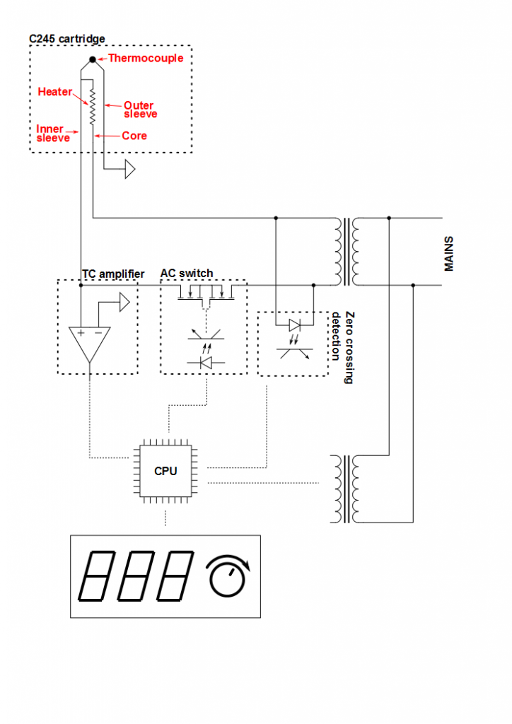
http://dangerousprototypes.com/forum/viewtopic.php?f=56&t=5264 over at dengerousprototypes forums. I came up with block schematic like this:
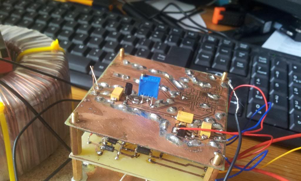
This is where I am right now:
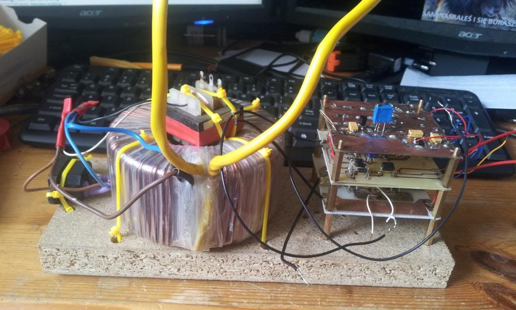
This is a very solid piece of ziptie engineering, but it's just temporary.
Power supply:
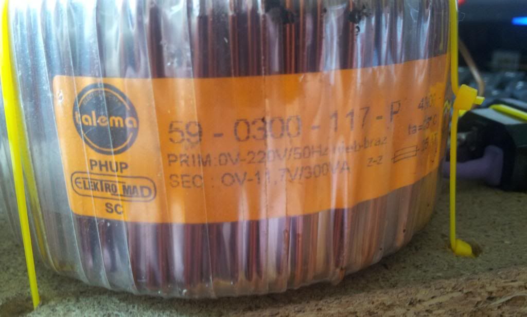
I's based on a huge 300W 12V halogene transformer, which I've bought for a few euros a few years ago. It will power the heater. This one is just temporary, as the original JBC uses a 150VA one with 23.5V secondary. 12V is being used instead of 24V, because I already had the transformer and because I could find parts that would work at 24V in my stash. Logic part is powered from a separate small 12V transformer (no idea where it came from). In final design I'll use either custom wound one, add my own low power winding by hand to an off-the-shelf transformer or use 2 separate ones.
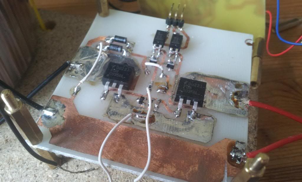
AC switch (bottom of the stack):
It uses 2 back to back connected N-MOSFETs same as the original JBC. I didn't have enough info (photos etc) to clone the drive circuit, so I came up with my own. It uses a charge pump and two optocouplers - one for turning the FETs on and the other for turning them off. I'm pretty confident, that original station uses something along those lines too (2 optocouplers can be seem on the teardown video). Entire prototype is made out of junk: mosfets came from some PC motherboards, optocouplers from some blown SMPS. The rest is chickenfood. I have tested it with some power resistors, and it generally works as intended.
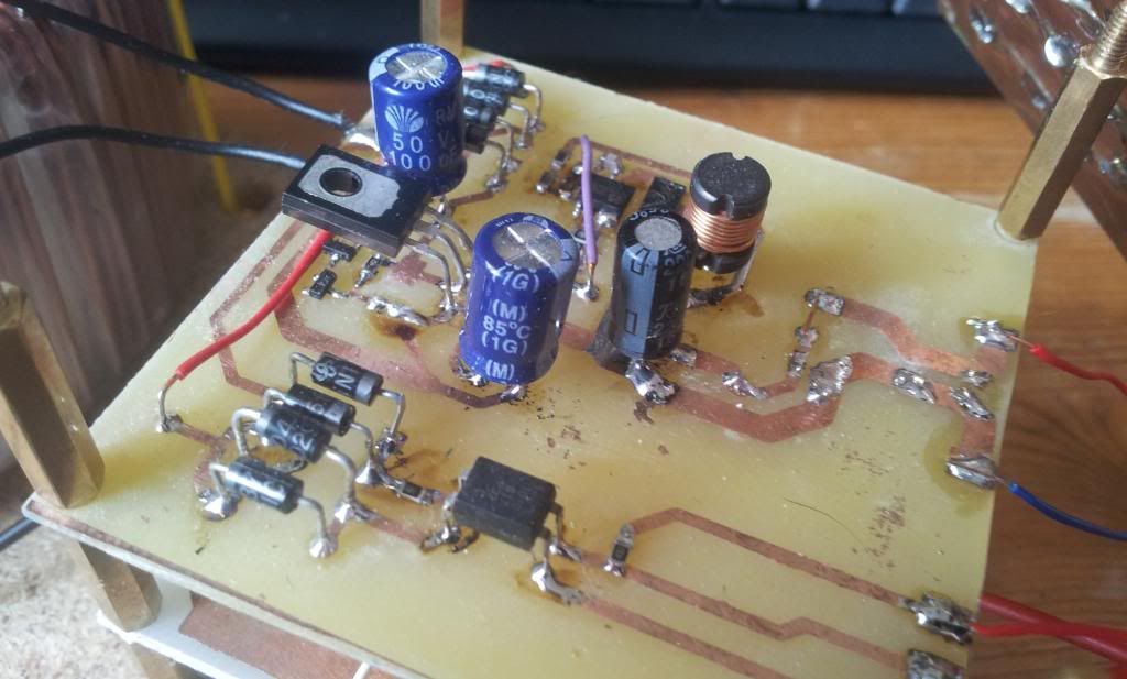
Logic power and zero crossing detector (2nd from the bottom):
Pretty simple 30V linear preregulator (zener + power transistor) to protect the circuit from surges and higher transformer output voltage when lightly loaded (an idea borrowed from user sparkybg over at DP forums), followed by an MC34063 (from junk pile) which is calculated for 6V@400mA output.
This board also contains a zero crossing detector which uses a full bridge and an optocoupler to generate positive spikes at zero crossing. I may change this to omit the optocoupler and sense the zero crossing from the transformer that powers the control logic.
Thermocouple amplifier and voltage reference (top board):
This one is not finished yet, as I don't have the opamp (MCP6V02) and cold junction sensor (MCP9701A). It has it's own 3.3V supply and a reference voltage source (TL431 - from junk). I expect to finish that until the end of this week.
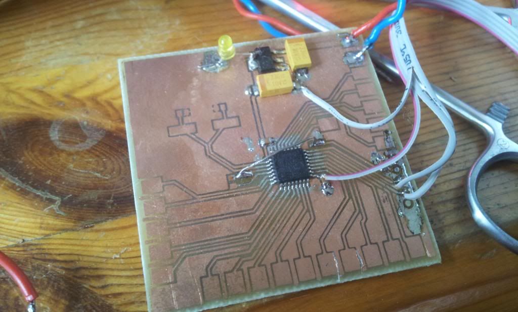
CPU:
CPU is gonna be a Cortex-M0 (STM32F030). This board contains an STM32F051, but it's not a problem, since F03x and F05x are pin to pin compatible.
Interface:
Right now I'm working on the interface, which will comprise of 3 7-segment displays for temperature readout, and a rotary encoder for temperature setting.
The only relatively non-jellybean components are the MCU and the thermocouple opamp.
I'll post some updates as I go.


