Author Topic: Logic-ICs - die pictures  (Read 13727 times)

0 Members and 1 Guest are viewing this topic.

Offline Capernicus

  • Frequent Contributor
  • **
  • !
  • Posts: 483
  • Country: au
Re: Logic-ICs - die pictures
« Reply #25 on: May 16, 2022, 03:09:46 am »
Are you drunk or something?

Something.

Capacitors are extremely costly in ICs and are used in highly specialized cases where there is no other option. Why and where would you even want to see capacitors here?

If u just need to twist a pair of wires together to make a cap, its not very expensive at all.

And you can't see the point of  making FPGAs, you just have no clue what is going on. Do you think ASICs happen out of thin air? They are designed and prototyped in FPGAs. Also ASICs are expensive and hard to impossible to update. But again, what it has to do with this thread?

Its to do with the thread, because we have some programmable logic devices here have we not noticed?
There's nothing to prototype in a logic design that a computer cant just run virtually in an ordinary gate model. (Like Logisim.), the actual hardware plumbing itself needen't really be tested at all if the electrical engineer actually wires it up properly like he was supposed to learn how to.  its just a gate circuit conversion to real electricity, I dont think an fpga even helps with that anyway, and its actually the only job to do.

FPGA's are just for people that cannot do hardware and want to pretend they are electrical engineers when they are not.
« Last Edit: May 16, 2022, 03:13:21 am by Capernicus »
 

Online ataradov

  • Super Contributor
  • ***
  • Posts: 11248
  • Country: us
    • Personal site
Re: Logic-ICs - die pictures
« Reply #26 on: May 16, 2022, 03:17:56 am »
Ah, you are one of the old people that can't cope with the new technology and think everyone needs to be stuck in the 70s simply because you can't learn new things anymore.

You really have no clue what you are talking about when it comes to FPGAs.
Alex
 
The following users thanked this post: MegaVolt, Capernicus

Offline Capernicus

  • Frequent Contributor
  • **
  • !
  • Posts: 483
  • Country: au
Re: Logic-ICs - die pictures
« Reply #27 on: May 16, 2022, 03:27:38 am »
Ah you grabbed my king off the board cause then u get to win.    :-DD
« Last Edit: May 16, 2022, 04:23:11 am by Capernicus »
 

Online magic

  • Super Contributor
  • ***
  • Posts: 6779
  • Country: pl
Re: Logic-ICs - die pictures
« Reply #28 on: May 16, 2022, 05:50:44 am »
Nah, he writes from a parallel universe in which capacitors are gain devices.
Posts about capacitor amplifiers every few weeks and now also capacitor logic :D
 

Offline Capernicus

  • Frequent Contributor
  • **
  • !
  • Posts: 483
  • Country: au
Re: Logic-ICs - die pictures
« Reply #29 on: May 16, 2022, 06:05:13 am »
How is not knowing how to do something supposed to make someone look cool.
Oh I know, its when you all dont know the same thing together!!!!
You cool guys know something I don't,  but when that happens to me it doesn't work for some reason, cause everyone seems to know the thing I dont.
« Last Edit: May 16, 2022, 06:42:27 am by Capernicus »
 

Offline gnif

  • Administrator
  • *****
  • Posts: 1676
  • Country: au
Re: Logic-ICs - die pictures
« Reply #30 on: May 16, 2022, 08:13:27 am »
why do they call them dies,  is it because the indians' come out of their genocide pit to get ya if you get this far in engineerin'?

Racism is not tolerated here, first and only warning.

FPGA's are just for people that cannot do hardware and want to pretend they are electrical engineers when they are not.

Settle down mate, post on topic or don't post at all.
Your rant about what you feel people can & can't do and what you think of them is out of place here.
« Last Edit: May 16, 2022, 08:18:25 am by gnif »
 
The following users thanked this post: RoGeorge, Noopy

Offline Simon

  • Global Moderator
  • *****
  • Posts: 17814
  • Country: gb
  • Did that just blow up? No? might work after all !!
    • Simon's Electronics
Re: Logic-ICs - die pictures
« Reply #31 on: May 16, 2022, 05:38:18 pm »
I deleted his first post, one more and he's banned, I'm not wasting time cleaning his mess up.
 
The following users thanked this post: gnif, Noopy

Offline NoopyTopic starter

  • Super Contributor
  • ***
  • Posts: 1732
  • Country: de
    • Richis-Lab
Re: Logic-ICs - die pictures
« Reply #32 on: May 30, 2022, 09:11:38 am »


DL003, a brother of the 74LS03 built in the Halbleiterwerk Frankfurt Oder. The DL003 contains four NAND gates with two inputs. S3 tells us it was produced in March 1984.


It turns out that the die is very similar to the DL020 (https://www.richis-lab.de/logic09.htm) which offers two NAND gates with four inputs each. The two devices are based on the same design. The metal layer creates the functions of various logic circuits with the underlying elements. Fittingly the designation DL003 is found on the upper edge.


The direct comparison with the DL020 shows three small differences apart from the metal layer. The red and the yellow resistors are not directly connected to Ucc in the DL020, so that they can be used more variably. The green marked resistor is also not directly connected to Ucc on the DL020. It offers an additional tap too.


The circuit of the DL003 is a bit simpler compared to the DL020 because the highside transistor at the output is missing. In addition the DL003 lacks the resistor that bridges the base-emitter of Q5 in the DL020 and ensures a faster switch-off.


The DL003 seen here was manufactured in June 1986 (U6).


It can be seen that this module is already based on the new design which was the basis for the DL020 (produced in January 1986). On the right edge, the number 04 has been incremented to 05. Most likely this is the revision of the metal layer, which had to be adjusted.

The use of a common basic design that creates different gate arrangements via the metal layer makes the production more efficient because you need less masks (at least back in the days in GDR).


https://www.richis-lab.de/logic13.htm

 :-/O
 
The following users thanked this post: SeanB, RoGeorge

Offline NoopyTopic starter

  • Super Contributor
  • ***
  • Posts: 1732
  • Country: de
    • Richis-Lab
Re: Logic-ICs - die pictures
« Reply #33 on: June 24, 2022, 03:50:40 am »


Some more standard logic. The Texas Instruments SN7400 contains four NAND gates with two inputs each. The Soviet variant of this gate is the K155LA3 (https://www.richis-lab.de/logic11.htm).


The edge length of the die is 0,93mm.

You can find the Ti logo in the lower right corner. In addition to the contacts to the substrate, the frame structure also shows some auxiliary structures that allow monitoring the manufacturing quality.

In contrast to the K155LA3, no retentions for alternative functions can be seen here.


946C  :-//
Name and revision?


The datasheet shows the generally known circuit of a NAND gate.

Push-pull output stages are located at the outputs. The SN7403 also offers four NAND gates with two inputs each, but has just open-collector outputs. For the output high-side transistor, a single transistor was powerful enough. The D220 (https://www.richis-lab.de/wafer01.htm) uses a Darlington pair for the highside.


The individual elements of the gates can be easily identified.  :-+


https://www.richis-lab.de/logic14.htm

 :-/O
 
The following users thanked this post: SeanB, RoGeorge

Offline NoopyTopic starter

  • Super Contributor
  • ***
  • Posts: 1732
  • Country: de
    • Richis-Lab
Re: Logic-ICs - die pictures
« Reply #34 on: June 28, 2022, 03:19:38 am »


Now here we have a SN7402. It contains four NOR gates.


The edge length of the die is 0,93mm. The Ti logo is located in the lower right corner. There is a certain similarity to the SN7400, but at the same time independent of the circuit itself there are some differences in the structures.

While on the SN7400 the ground potential is distributed via a frame structure, on the SN7402 there are GND traces that run through the circuit.

The number sequence 946C, which is shown on the SN7400, cannot be assigned. The numbers 02C on the SN7402 on the other hand certainly refer to the specific designation of the logic module.

The protection diodes at the inputs are clearly visible in the SN7400 but not in the SN7402.


The circuit diagram in the datasheet shows how the gates work. The two input transistors control two parallel connected driver transistors, which drive a push-pull stage.


The components of the circuit diagram can all be found on the die. Only the protection diodes are not directly visible. The bondpads, which represent the inputs, have additional frame structures that are not found on the outputs. This suggests that the protection diodes were integrated under the bondpads.


https://www.richis-lab.de/logic15.htm

 :-/O
 
The following users thanked this post: SeanB

Offline NoopyTopic starter

  • Super Contributor
  • ***
  • Posts: 1732
  • Country: de
    • Richis-Lab
Re: Logic-ICs - die pictures
« Reply #35 on: July 04, 2022, 03:28:36 am »


One more standard logic part. The Texas Instruments SN7404 contains six inverter gates.


The die is 1,1mm x 0,8mm in size. The basic design is the same as in the 7402 (https://www.richis-lab.de/logic15.htm). The 04C characters in the center of the die refer to the specific variant of the 74 family.


The datasheet shows the unsurprising structure of an inverter. The input transistor is followed by a driver stage which generates differential control signals to drive both highside and lowside transistor.


A inverter gate is less complex than a NOR gate in the 7402 but since there are six inverters the 7404 requires significantly more area. Three inverters are located in the lower half of the die and the other three inverters are located in the upper half of the die.


The individual circuit parts can be easily identified.


https://www.richis-lab.de/logic16.htm

 :-/O
 
The following users thanked this post: SeanB, RoGeorge

Offline NoopyTopic starter

  • Super Contributor
  • ***
  • Posts: 1732
  • Country: de
    • Richis-Lab
Re: Logic-ICs - die pictures
« Reply #36 on: July 08, 2022, 06:55:19 pm »


The SN7474 contains two Flip-Flops.


The die is 1,4mm x 1,0mm.

The design is the same as in the SN7402 (https://www.richis-lab.de/logic15.htm) and in the SN7404 (https://www.richis-lab.de/logic16.htm). However a GND metal frame is integrated like in the SN7400 (https://www.richis-lab.de/logic14.htm). The characters 74C in the metal layer match the model designation.


https://www.richis-lab.de/logic17.htm

 :-/O
 
The following users thanked this post: SeanB, RoGeorge

Offline NoopyTopic starter

  • Super Contributor
  • ***
  • Posts: 1732
  • Country: de
    • Richis-Lab
Re: Logic-ICs - die pictures
« Reply #37 on: July 12, 2022, 03:40:18 am »


SN7493, a binary counter.


In the datasheet you can find the logical block diagrams of the 7490, the 7492 and the 7493, counting to 10, to 12 and to 16.


The dimensions of the die are 1.4mm x 1.3mm.

With the large protection diodes the design is similar to the SN7400 (https://www.richis-lab.de/logic14.htm).


In the lower right corner the numbers 93 and some not connected elements can be found, including the basis for two additional bondpads. These structures and the fact that the SN7490, the SN7492 and the SN7493 share a datasheet suggest that the three devices are based on the same design and just the metal layer has to be changed.


https://www.richis-lab.de/logic18.htm

 :-/O
 
The following users thanked this post: SeanB, RoGeorge

Offline NoopyTopic starter

  • Super Contributor
  • ***
  • Posts: 1732
  • Country: de
    • Richis-Lab
Re: Logic-ICs - die pictures
« Reply #38 on: July 16, 2022, 06:50:49 pm »


One more 9000 logic (like the 9300: https://www.richis-lab.de/logic10.htm).
The 9334 is a 8Bit latch.


The datasheet shows a functional diagram of the 9334.

In the lower area the eight memory cells can be seen. In the upper area differential signals are generated from the potentials addressing the individual memory cells. Enable and Data are linked.


The die is 2,1mm x 1,5mm.


In the upper area the metal layer depicts the characters AO and 34. Under the metal layer on the left edge you can barely see the characters AO34U. 34 probably marks the variant 9334 within the 9300 logic family.


At the bottom of the die there are the characters U6B, which may represent a revision designation.


The eight memory cells are easy to recognize. The eight lines in the middle of the dies are also striking. These are the differential address lines, the data signal and the enable signal. The clear signal is routed between the memory cells and the middle signal distribution in kind of a ring line.


The vertical stripes represent the 16 AND gates. They are NPN transistors with multiple emitters. The red stripe is the base area. A pull-up resistor connects it to the positive supply. A smaller, isolated, red area represents the collector contact. The collector is the output of the gate. The horizontally running leads contact square emitter areas within the base region. If one of the lines carries a low potential, it sinks the positive base potential and a low level is set at the output. Only if a high level is present at all connected lines the respective gate can output a high level at the collector.


https://www.richis-lab.de/logic19.htm

 :-/O
 
The following users thanked this post: SeanB, RoGeorge

Offline NoopyTopic starter

  • Super Contributor
  • ***
  • Posts: 1732
  • Country: de
    • Richis-Lab
Re: Logic-ICs - die pictures
« Reply #39 on: August 18, 2022, 07:05:33 pm »


The DS8205 produced in the Halbleiterwerk Frankfurt Oder is a so-called 1 out of 8 binary decoder. One of eight outputs can be activated via three inputs. The DS8205 corresponds functionally to the Intel P8205 and the 74S138.

The string T8 stands for a manufacturing in August 1985.


The datasheet of the DS8205 shows the simple design. The input signals are processed to differential control signals. At each output a quad NAND gate is connected to the necessary control lines.


The die of the DS8205 is 1,9mm x 1,2mm. The auxiliary structures known for the HFO can be found on it. At the top right corner there are the numbers 03, which indicate the revision of the design. The numbers below appear to have a reference to the masks used. At the bottom edge in the milling line the remains of the crosses can be seen that allow to check the alignment of the masks against each other. At the top left the designation 8205 is shown.

At the top right are the input bondpads. The output bondpads are equipped with large push-pull transistors. The long NAND gates are integrated in the right area. The vertical transistors contacting a horizontal line represent an input of the respective NAND gate.


This DS8205 was manufactured in November 1985 (TN).


At the top right you can see that the revision has been incremented to 04. However, there are no visible differences to revision 03. A DS8205 manufactured in February 1998 also contains a revision 04.


The DS8205 shown here was manufactured in September 1989 (X9). It contains the revision 05 as well as a DS8205 with the date code X3 (March 1989).


Revision 05 also shows no functional differences to revisions 03 and 04. However, the contact areas from the metal layer to the silicon appear to be slightly larger.

Perhaps the old masks had reached the end of their service life or the process has changed slightly and new masks were therefore created.


In detail you can see the Schottky transistors described in more detail with the DL020 (https://www.richis-lab.de/logic09.htm). The base contact is wider than the base area and thus simultaneously contacts the collector area (green). A Schottky diode is formed at the interface between the metal and the collector doping. The more powerful transistors have an additional contact to the collector surface (red) in addition to the contact to the base surface.


https://www.richis-lab.de/logic20.htm

 :-/O
 
The following users thanked this post: SeanB, RoGeorge

Offline NoopyTopic starter

  • Super Contributor
  • ***
  • Posts: 1732
  • Country: de
    • Richis-Lab
Re: Logic-ICs - die pictures
« Reply #40 on: September 02, 2022, 07:10:34 pm »


The Motorola MC14094B is a 8Bit shift register with tri-state outputs. The datasheet advertises the device as pin compatible with the CD4094B.


The blockdiagram shown in the datasheet shows the structure of the MC1409B. There are eight registers connected in series, which represent a shift register. Next to each register a latch is integrated which controls a tri-state output stage. At the end of the shift register the data is output via Q s and Qs.


The die is 2,00mm x 1,85mm in size. The structures under the metal layer are poorly visible.


With the characters 14094B the designation of the circuit is shown on the die. To the left of this are some markers that allow to check the alignment of the masks against each other. The meaning of the characters C60E remains unclear.


The individual sections of the MC14094B are clearly visible. Between the output bondpads are the push-pull output stages (red). The largest part of the area is taken up by the two times four areas that contain registers, latches and drivers for the output stages (purple). In the upper right area a conspicuously large driver is integrated (green), which amplifies the clock signal sufficiently to be able to supply the many transistors in the rest of the circuit.


The details of the circuit are difficult to see due to the poor contrast of the different areas.


https://www.richis-lab.de/logic21.htm

 :-/O
 
The following users thanked this post: SeanB, xrunner, RoGeorge

Offline NoopyTopic starter

  • Super Contributor
  • ***
  • Posts: 1732
  • Country: de
    • Richis-Lab
Re: Logic-ICs - die pictures
« Reply #41 on: September 13, 2022, 08:55:00 am »


The RCA CA3161 is a BCD/7-segment decoder similar to the D146 / D147 (https://www.richis-lab.de/logic02.htm), but it also contains constant current sinks. 7-segment displays can thus be connected directly without series resistors. The module provides a current flow between 18mA and 35mA.


The datasheet shows the character containing a minus sign and the letters E, H, L and P in addition to the numbers.


The edge length of the die is about 2mm.


10397B could be the internal designation of the circuit.


The individual circuit blocks can be identified relatively easily. At the lower edge there is the input buffer (yellow). With the help of the bias generator in the left area, the input signals are evaluated. Towards the top the buffer outputs the input signals differentially.

The binary value is first converted into a decimal value (green) before another circuit (blue) generates the necessary 7-segment control signals.

The seven output stages are integrated in the upper area of the die (red).


The input buffers are designed like differential amplifiers and provide differential outputs. At the upper end the current value is output via lowside transistors.


The differential binary value, here 1110, controls a matrix containing eight long transistors. Judging by the structure and the wiring they are probably NPN transistors. The binary value is applied to the base areas. Subsequently all but one of the 15 continuing lines are switched to high via the emitter areas. The inactive line stands for the selected symbol.


This is followed by another matrix that controls the final stages of the device. Seven lines run horizontally, which stand for the seven segments. On the left they are connected to current sources, which provide a high level in the inactive state. The output stages that receive a high level are activated and the corresponding segments light up. Consequently the matrix must deactivate the segments that are not needed. On the right side five lines are led to the output stages a, b, c and d. The lines for segments f and g run to the left of the matrix. The area of these lines gives the impression of having a special function. In fact, however, it is just an undercrossing of the metal layer.

The exact function of the areas below the matrix remains unclear. From above another supply is fed from the V+ potential, but it is distributed differently from the previous matrix. Since the inactive control line must deactivate segments and the matrix should remain inactive with the high levels of the other control lines, it must almost be a PNP structure. The substrate could be used as ground. However, there seems to be a lack of a strong low level to drive the selected transistor strip. One can only assume that the leakage currents are high enough to drive the transistor and thus pull the necessary lines to a low level.  :-//


The datasheet shows the implementation of the current limitation. There is a resistor in the emitter path of the output transistor. As the current increases the voltage drop across the resistor increases and the lower transistor diverts more and more base current from the output transistor. Eventually the specified LED current is established.


The large output transistors are integrated directly at the bondpads. A slightly thicker GND line guarantees the necessary current carrying capacity. Around the GND line there is the current limiter.

Darlington transistors control the output stages. There are quite large resistors in their collector paths.


On the die of the CA3161 considerable areas are reserved for another function. Two very large output stages are integrated in the lower left corner. Above the power amplifiers there is an input buffer as it is also used for the 7-segment control. It was obviously intended to switch on the two output stages alternately.

If you follow the lines you can see that the bondpad for the control of these output stages would be located at the right edge. The bondpad for segment e placed there would then be moved to the upper right corner. Similarly in the lower left corner, the bondpad for input 2^1 could be moved to the right freeing up two bondpads for the two outputs in that area.

Perhaps the additional circuit would allow multiplexing of two 7-segment displays.


https://www.richis-lab.de/logic22.htm

 :-/O
 
The following users thanked this post: SeanB, RoGeorge

Offline NoopyTopic starter

  • Super Contributor
  • ***
  • Posts: 1732
  • Country: de
    • Richis-Lab
Re: Logic-ICs - die pictures
« Reply #42 on: September 29, 2022, 09:13:15 pm »
I wasn´t happy with my explanation how these two matrices in the CA3161 do they job.
Now I know what the problem was! That is a I2L, a integrated injection logic!


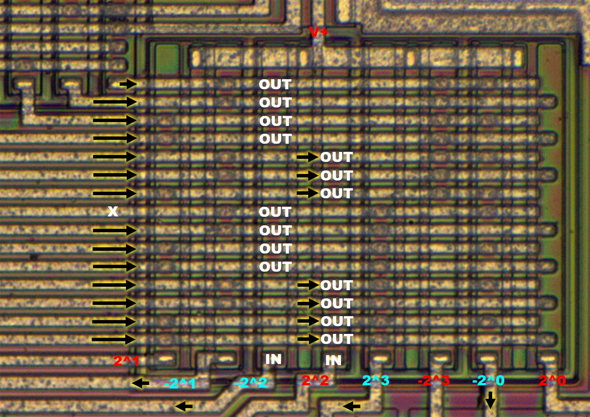
The binary value, here 1110, is located with its complementary value at the lower edge of the matrix. A low level at an input pin leads to an active low level at the lower edge of the matrix (2^3). A high level leaves the respective input open (2^0 - 2^2). The complementary connections behave correspondingly inverse to this.

The matrix contains a so-called Integrated Injection Logic, I2L. If there is a low level at one of the vertical stripes, the outputs remain inactive. Without a low level, the Integrated Injection Logic switches a low level to the outputs.

A total of 15 lines lead to the left. 15 lines are sufficient because no active control is needed for the number 8. The selected line remains inactive. All other lines carry a low potential.


At the input of an Integration Injection Logic there is the injector, a PNP transistor whose base is connected to the ground potential and thus serves as a current source. In this circuit, the injector is not directly connected to the positive supply, but to a current source. This probably reduces the power dissipation. Any number of lowside transistors can be connected to the input as a signal source. The outputs of an I2L gate are then again NPN transistors which switch to GND. Again, theoretically any number of outputs are possible.

On the die of the CA3161 the NPN transistors of an I2L gate can be seen as long vertical base strips, in which square emitter areas are located. An injector strip is integrated between two of these strips. The injector does not necessarily have to be designed as a long strip parallel to the NPN transistors. A single block at the upper end would be sufficient in principle. However, the long strip reduces the switching delay between the top and bottom NPN transistors. This feature can be critical, especially with long I2L gates, such as those present here.

The PNP transistor, operating as an injector, forms between the middle and adjacent p-doped strips. The n-doping, in which the strips are embedded, represents the base, which is connected to the ground potential via a buried heavy n-doping.


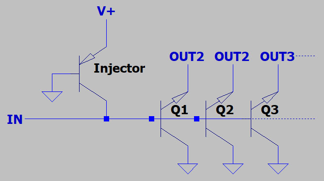
At first glance the structure of the NPN transistors corresponds to the usual design. In an n-doped well with a low-lying, heavily n-doped feed line, there is a p-doped area containing heavily n-doped elements. Normally, the lower n-doping represents the collector and the upper n-doping forms the emitter of the NPN transistor. However, here the transistor structure is used inverted. The lower well is operated like an emitter and the individual squares in the base doping operate as collectors. Therefore, the above schematic describes the physical structure more accurate.

The common transistor structure is advantageous because a thin base layer can be set there. Most of the electrons, which are released from the emitter, fly through the base zone and reach the collector. The doping gradient that occurs in the base region also has a beneficial effect on this movement. In an inversely operated transistor, the electrons that then leave the large-area collector have many more opportunities to leave through the base. Only a few electrons reach the small emitter.

NPN transistors certainly allow inverted operation. The breakdown voltage and and gain are then usually much lower. The same applies to the cutoff frequency. On the other hand the lower saturation voltage is advantageous. The negative effects can be advantageously influenced to a certain extent by the shape and doping of the structures. A more detailed consideration can be found, for example, in the IEEE article "Device Physics of Integrated Injection Logic" (IEEE Transactions on Electron Devices Volume 222, Issue 3, March 1975).


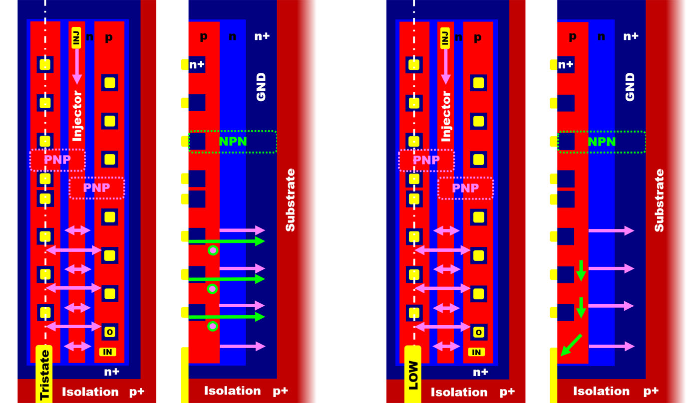
If no signal is present at the input of the I2L strip, the current flow through the injection transistor (pink) ensures that the NPN transistors become conductive and pull the outputs to ground potential (green).

If there is a low level at the input of the I2L strip, the free charge carriers of the injection transistor are diverted from the base area of the NPN transistor so that it remains blocked.


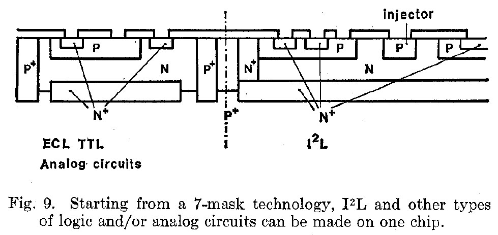
Integrated Injection Logic can be integrated into an n-doped substrate. However in the CA3161 there are also ordinary transistors, which usually require a p-doped substrate.

The paper "Integrated Injection Logic-Present and Future," published in the IEEE Journal of Solid-State Circuits (Volume 9, Issue 5, October 1974), shows how seven masks can be used to integrate I2L areas alongside conventional transistors. As usual for normal transistors a heavily p-doped substrate is used to isolate the individual transistors from each other. Above this is the NPN transistor with a buried, highly doped collector feed line. Heavily p-doped confinement structures provide lateral isolation.

The I2L region is isolated by a heavily n-doped well. The collector feed line can be used as the bottom element. In addition just some strongly n-doped, deep-reaching lateral boundary structures are required. This also explains the different appearance of the boundery structures of normal transistors and I2L regions on the die of the CA3161.


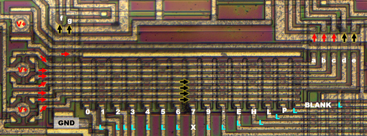
This first I2L matrix is followed by another I2L matrix, which ultimately controls the final stages of the device. Seven lines run horizontally, which stand for the seven segments. They are connected to current sources on the left, which provide a high level in the inactive state. The output stages that receive a high level are activated and the corresponding segments light up. Consequently, the matrix must deactivate the segments that are not needed. For this reason the number 8 is not present here, because without active intervention all segments are active and accordingly an 8 is displayed. Five lines lead to the right to the output stages a, b, c and d. The lines for the segments f and g run to the left of the matrix.

As with the first matrix, this is a Integrated Injection Logic too. At the top left is a dual power source. One path supplies the injector of the lower matrix, the second path supplies the injector of the matrix you can see here. Since the lines are not too high, it was sufficient to design the injector as a single element above the transistor strips.

Where no low level is present (X), the I2L transistors become active and deactivate the segments connected there (here d, e, f and g).


https://www.richis-lab.de/logic22.htm

 :-/O
 
The following users thanked this post: SeanB, RoGeorge

Offline mister_rf

  • Contributor
  • Posts: 33
  • Country: ro
Re: Logic-ICs - die pictures
« Reply #43 on: January 17, 2023, 12:17:30 pm »
Texas Instruments SN7400 Quad NAND gate in flat pack package. 1965.  :)

 
The following users thanked this post: SeanB, edavid, doktor pyta, laneboysrc, RoGeorge

Offline brabus

  • Frequent Contributor
  • **
  • Posts: 326
  • Country: it
Re: Logic-ICs - die pictures
« Reply #44 on: January 17, 2023, 12:31:41 pm »
This last photo is absolutely MIGHTY. Amazingly cool.
 

Online iMo

  • Super Contributor
  • ***
  • Posts: 4780
  • Country: pm
  • It's important to try new things..
Re: Logic-ICs - die pictures
« Reply #45 on: January 17, 2023, 12:48:53 pm »
Imagine all those chips produced - how many tons of gold you may get from the SN74 series?  ::)
 

Offline NoopyTopic starter

  • Super Contributor
  • ***
  • Posts: 1732
  • Country: de
    • Richis-Lab
Re: Logic-ICs - die pictures
« Reply #46 on: February 19, 2023, 07:23:16 pm »


The DL074 built by the Halbleiterwerk Frankfurt Oder contains two edge-triggered D-Flip-Flops. The datasheet specifies a maximum clock frequency of 25MHz. With the designation PL074, the component seen here is a so-called "Bastlertyp" (hobbyist type) that does not necessarily comply with all specifications. The signs U9 stand for a production in September 1986.


There is a large and relatively thick carrier in the package, which improves the heat dissipation of the circuit.


The dimensions of the dies are 3,0mm x 1,8mm.


The designation on the side of the die shows that this is actually a DL193. The DL193 is a binary counter with four digits, it consequently contains four flip-flops. Apparently, an alternative metal layer has been developed that connects two of the flip-flops completely and independently to the outside. Synergies were often sought in the GDR semiconductor industry, as it became increasingly difficult over time to produce the many different integrated circuits due to limited capacities.


The revisions of eight masks can be seen on the side. The metal layer was revised once. Perhaps revision 2 is the variant that turns the DL193 into the DL074.


In the middle of the die, some unused vias can be seen. These probably resulted from the adaptation to the functionality of the DL074.


https://www.richis-lab.de/logic23.htm

 :-/O
 
The following users thanked this post: SeanB, RoGeorge

Offline NoopyTopic starter

  • Super Contributor
  • ***
  • Posts: 1732
  • Country: de
    • Richis-Lab
Re: Logic-ICs - die pictures
« Reply #47 on: February 20, 2023, 08:25:18 pm »
Hm, it seems I was wrong:
The DL074 has 14 pins. This PL074 has 16 pins.  >:D
I assume this part got a wrong label and it is just a D193, nothing more.

Offline NoopyTopic starter

  • Super Contributor
  • ***
  • Posts: 1732
  • Country: de
    • Richis-Lab
Re: Logic-ICs - die pictures
« Reply #48 on: May 05, 2023, 08:53:10 am »


No let´s take a look into a real DL074. The DL074 from the Halbleiterwerk Frankfurt Oder is a dual flip-flop with set and reset inputs. As a low power Schottky TTL the DL074 corresponds to the 74LS74.

V2 stand for a production in February 1987.


The die was damaged during exposure, but most of the structures can be seen. The edge length of the die is 1,2mm. The numbers 03 on the top edge show that this is a third revision. Several masks are shown on the lower edge and in the left area.


The DL074 seen here was manufactured in May 1988 (W5). It contains the same design as in the first DL074.


With the characters W8 this DL074 was manufactured in August 1988.


The die of this DL074 is heavily damaged. Either the IC was electrically overloaded or there are signs of corrosion.

The numbers 05 on the right edge show that the design has been revised in the meantime. In the circuit itself, no differences to revision 04 can be seen. Just the unused edge area was made thinner and the bondpads were moved a little.


Due to the severe damage, the circuit parts are difficult to recognize.


https://www.richis-lab.de/logic24.htm

 :-/O
 
The following users thanked this post: SeanB, RoGeorge

Offline NoopyTopic starter

  • Super Contributor
  • ***
  • Posts: 1732
  • Country: de
    • Richis-Lab
Re: Logic-ICs - die pictures
« Reply #49 on: May 14, 2023, 06:22:53 pm »
There are some updates to the DL logic, the AND and NAND gates to be exact.
The HFO used a basic design that is the same for the following three logic gates. The difference is just the metal layer.


We already had the DL003, a four 2-Input NAND gates.


The schematic in the Radio Fernsehen Elektronik states there should be a Push-Pull output stage but here it is missing although the circuit parts are on the die.  :-//


A second DL003 lacks the highside stage too.


The DL008 is new. It contains four 2-Input AND gates.


The AND is pretty similar to the NAND and hey, here we have the highside stage too!


Here you can see the different metal layers while the basic design is the same.


A second DL008, now this one is a little different!


If you put the revisions 4 and 5 of the DL008 next to each other, you can easily see the differences. The revision refers to the metal layer and applies specifically to the respective logic device. The DL020 with revision 03 (right) already used the newer design, which is also used by the DL008 with revision 05. If you ignore the metal layer, you can see the evolution of the basic design.

The active elements of the basic design did not change between the revisions, only the resistors were adapted. The top resistor (cyan) has been changed from a transparent material, presumably the base doping to a narrow strip, of the standard resistor material. It is the 75Ω resistor in the supply line of the output stage. It is present on each of the symmetrically constructed sides once in the upper and once in the lower area.

The other two resistors in the upper section (red/yellow) were permanently connected to the Ucc potential in the earlier revision. In the newer revision 04 they have been relocated so that they can be used more freely. In the DL008 the used resistor (red) is still connected to Ucc. But the Ucc line has been widened at this point. With the DL020, this resistor could be used as base-emitter resistor for the transistor VT1 (We will see that soon.) This would not have been possible with the older design.

In the lower section, next to the series resistor in the supply of the output stage, two resistors were also adapted, which in the older design were permanently connected to the Ucc potential (green). In the newer design, these are two resistors connected in series, whose center tap can be connected to the Ucc potential (center). With a different design of the metal layer, however, the two resistors can also be used independently of the Ucc potential (right).


Here we see the DL020 we already had. It contains two 4-Input NAND gates.


And here we have the additional Base-Emitter-resistor that isn´t shown in the schematic in the Radio Fernsehen Elektronik. It seems like they tried to speed up Q5 (VT1) a little.


Update DL003 (4*2-IN-NAND):
https://www.richis-lab.de/logic13.htm

DL008 (4*2-IN-AND):
https://www.richis-lab.de/logic25.htm

Update DL020 (2*4-IN-NAND):
https://www.richis-lab.de/logic09.htm

 :-/O
 
The following users thanked this post: SeanB, RoGeorge


Share me

Digg  Facebook  SlashDot  Delicious  Technorati  Twitter  Google  Yahoo
Smf