Using these formulas, calculate the ABCD parameters:
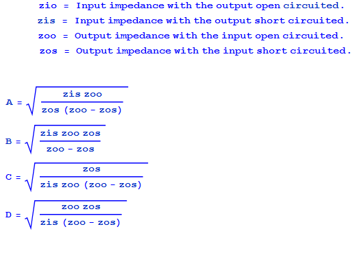
Since your two-port is reciprocal, only 3 of the 4 measurements are needed to get the 4 ABCD parameters.
So, I did try this method.
I think this method should have less measurement error. Changing from Impedance Measurement to Gain-Phase will mean changing fixtures/equipment. Two sets of Calibrations and two sets of systematic error.
One issue I was observing was that open-circuit impedances were garbage at low frequencies. This makes sense, since the impedance approaches infinity at DC, and the impedance measurement is limited.
To remedy this, I decided to add a shunt R at the output. This term preserves the impedance measurement at low frequencies. By measuring DUT+Shunt, then Shunt alone, I should be able to separate out the DUT, in theory...

For clarity, here is my measurement setup:

For the shunt, I did measure Z1O Z1S, Z2O Z2S, and confirmed that the network is reciprocal and symmetrical.

The ABCD for the DUT+Shunt, and Shunt, both look reasonable on their own.
When I attempt to remove the shunt by division, something strange happens. Here is the A parameter of the isolated DUT matrix. There are a few discontinuities in both the A and C parameters.

I think I have isolated how this is happening.
Since the shunt is of the form (The measured shunt is approximately this)
$$ \begin{bmatrix} 1 & 0\\ Y & 1 \end{bmatrix}$$
The equation for the DUT without Shunt is:
$$ \begin{bmatrix} A*1 + B * -Y & A*0 + B*1\\ C*1 + D * -Y & C*0 + D*1 \end{bmatrix}$$
So the $$A-B*Y$$ and $$C-D*Y$$ have a subtraction in them. Complex add/sub seems to give some messy results. I plotted A, B*Y, and the subtraction to better understand.

The discontinuity seems problematic. Still, I continued to see what the final results would look like.
As a sanity check, I wanted to compare the individual measurements with the measurements of the entire network:

I used the ABCD of the shunt, removed it from the ABCD of DUT1, DUT2, and DUT1&2.
Then I calculated DUT1 * DUT2 (cascading) to get the calculated DUT1&2
Here are the plots:

While they roughly have a similar shape, they do not match as I would expect.
There must be measurement error somewhere. The low frequency, low-impedance measurements in the shunt and low-z DUT, seem to have a slight imaginary component where there shouldn't be. This causes significant phase shift at very low Z.
I think my next step will be to try measuring only high-frequency response with the impedance analyzer. Then, use DC measurements to fill a point at, say, 0.1Hz. Then use curve-fitting to generate the transfer function equation I am after.


