Hello,
I bought this
cheap CC PSUs to power 10W 900mA LEDs.
I would like to make LEDs dimmable, I know I can add external PWM dimmer and be done, but it's also a learning oportunity.
Even tho I have nothing against natural selection I thought I would ask input before I became a victim of it

I know the risk and dangers of messing with it and high voltage so no need for fear mongering.
MCU marking: IAD21CX (I think)
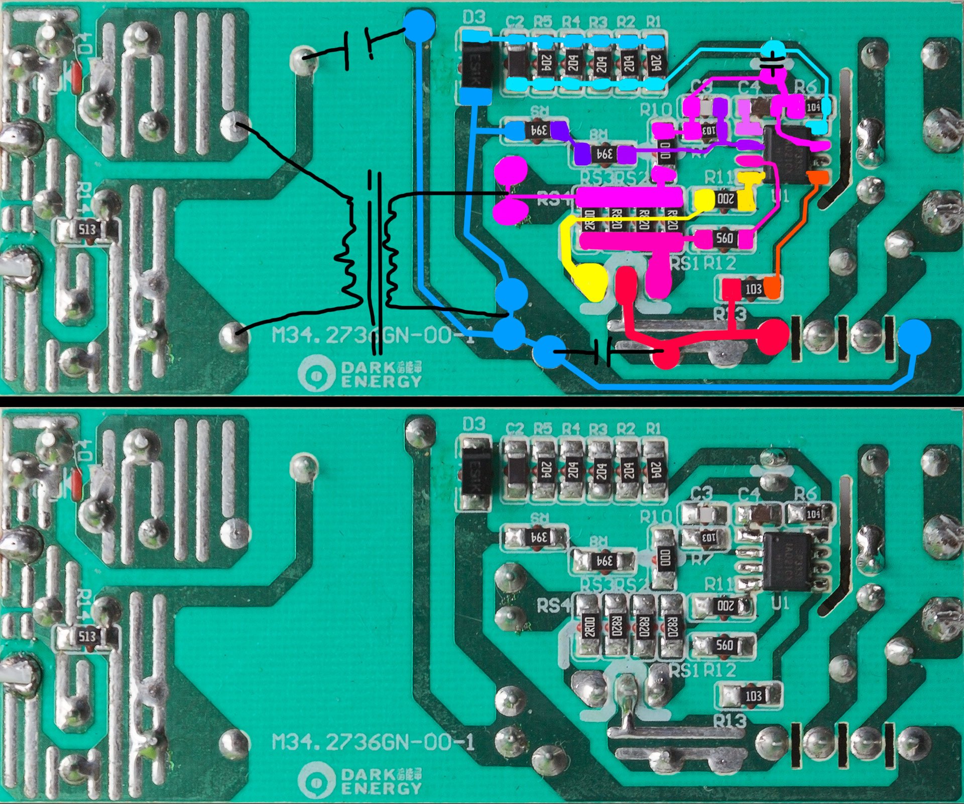
I did some tracing (skipped low side and AC side) and this is what I found:
From what I understand they used simple resistors (2x 390K on a low side and 10K on high side) to power the MCU (I'm assuming it's VGND and VIN of the MCU).
Current shunt is parallel array of 1x 2R00 and 3xR820 (0.24 Ohms total). Shunt height side goes thru 56 Ohm resistor to MCU, shunt low side jumps via 0 Ohm resistor and goes to another IO, tho this signal is pulled down via 10K resistor to VGND.
I'm guessing diode on the top left and 200K 5 resistor array is for transformer freewheeling and MCU sensing of it? That part of the circuit is most mysterious to me...
I assume to make it adjustable I need to increase shunt voltage difference (decrease lower shunt signal voltage) to trick MCU that load uses more current than it actually is.
I will stop here and see what smarter people has to say about this circuit.
Cheers.