Author Topic: My Advanced Realistic Humanoid Robots Project  (Read 2052 times)

0 Members and 1 Guest are viewing this topic.

Offline artbyrobotTopic starter

  • Contributor
  • Posts: 26
  • Country: us
    • www.artbyrobot.com
My Advanced Realistic Humanoid Robots Project
« on: May 01, 2024, 08:21:56 pm »
This is my real life terminator/Data from Star Trek/Westworld type humanoid robots project. It is a long term project. I plan to post updates occasionally to share my progress and seek feedback, suggestions, advice, etc.  So far I have plans to build Adam, Eve, and Abel robots. All of these are Bible characters.  I want the robots to ultimately move like a human, be able to walk, run, jump, do chores, dance, do sports, have conversations realistically, paint, do sculpture, make more robots, etc.


I plan to do most of the electronics custom - so custom microcontrollers, custom motor controllers, custom power supply, custom battery management system, custom sensor support circuitry, etc.  I am a electronics beginner so guidance on these parts is welcomed.

Robot Features Planned

I plan to start out making the right arm and hand, rigging them up with servo motors, connecting that up to a pc, and getting it to grasp. From there I will develop the head and torso just enough to be able to code the robot arm to make his other arm and the rest of his own body for me. The bot will have silicone skin and look realistic and move realistic. It will have artificial lungs for cooling. It will have spandex ligaments and cable drive systems to imitate muscles. It will have sensors to feel if it bumps into things and it will have webcam eyes. It will have a speaker in the mouth to speak with and the mouth will move to lipsync what it is saying. It will have facial expressions. It will have advanced artificial intelligence. It will run on battery and/or power cable depending on the situation.

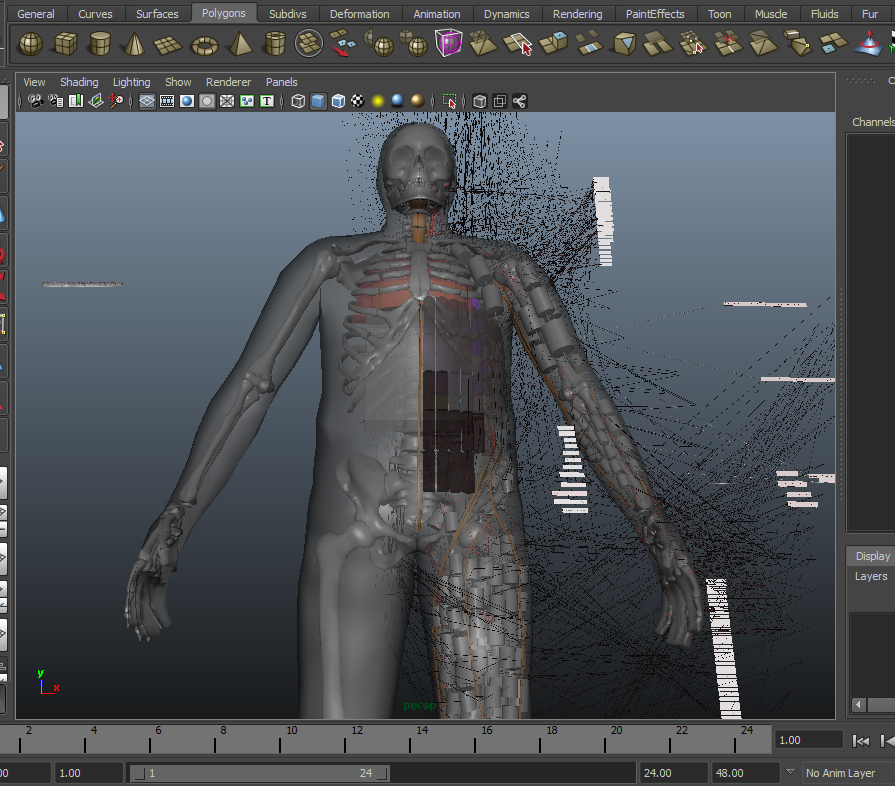
First of all, I ended up caving in and doing a full blown 3d model blueprint of the robot's entire skeletal structure to scale along with outer shape mesh and then modeled out every actuator cable "muscle" and labeled each of them and modeled all of its motors and placed them and modeled various other bits like the main onboard pc and cooling systems (artificial lungs and artificial heart). Also modeled its batteries and placed them. Only had to do half of the body since the other half of body is symmetrical. I realized that with the tight tolerances I'm dealing with, I had to make custom servos and custom pcbs for the servos control and custom pulley systems to "down-gear" the servos. I also realized that with such tight tolerances I needed to 3d model everything to figure out where to fit everything since it will all be a tight fit with little room for error and once I mount a servo, it is a real pain to move it later. The 3d modeling blueprint job was a major project in itself but well worth it in helping me visualize everything better and figure out where to locate everything specifically.  I also made blueprints for the motor controller and microcontroller custom circuitry.

I also purchased the main brains pc to be mounted in the torso. I even purchased cameras to be the eyes for it. The main brains pc will be a mini itx motherboard gaming pc basically.

actual build I went with:

Intel Core i5-10400 2.9 GHz 6-Core Processor - $165

MSI MPG B560I GAMING EDGE WIFI Mini ITX LGA1200 Motherboard - $170

G.Skill Ripjaws V Series 32 GB (2 x 16 GB) DDR4-3200 CL16 Memory - $140

Western Digital Blue SN550 1 TB M.2-2280 NVME Solid State Drive - $99

DC 12V input 300W high power pico DC-ATX 24Pin mini ITX - $20

GOLF CART DC BUCK CONVERTER 20 AMP 48V 36V VOLT VOLTAGE REDUCER REGULATOR TO 12V - $20

I will use 10 in series lithium batteries to produce 30v-42v input power into the 12v regulator which will feed the 300W atx 24pin mini ITX power supply. Note, however, that as with all power systems, I will have both a wall plug AC to DC converter custom power supply to run off wall power and a battery power supply to run off battery power so that the robot has multiple powering options - ie able to run off wall to assist its internal batteries while charging. It will have a retractable plug that comes out of its lower back to plug itself into wall outlets when it walks into a room and needs to recharge or run for extended periods while its batteries remain topped off for room changes or ventures into outdoors. It will have the ability to strap on a external battery backpack optionally for extended operation without access to AC power. This is useful for operations like sports or mowing the lawn.  It will have multiple external battery backpacks so that it can have one charging while using the other for constant uptime.

For the eye cameras I went with: ELP USB camera 1080p 2 megapixel, wide angle, low light x2 for $98.42

This gaming pc in the chest of the robot will run all the AI and high level planning and movement decisions. This will communicate via USB to a series of Arduino mega barebones custom microcontrollers located throughout the robot's body in order to give movement instructions to the Arduinos and also retrieve sensor feedback from the Arduinos which will be monitoring joint angle positions with mini potentiometers, strain gauges on various pressure points to measure touch sensing, amp current measuring boards (acs712) to measure amount of power being drawn by motors for collision detection and weight of exertion estimation for holding things or w/e other interactions with environment are being detected, etc. So, many inputs will be retrieved by the main gaming pc and its AI systems will make decisions and make course corrections based on all this feedback it gets from sensory systems.

Note: I did at one point begin sewing in MG996r servo motors into the arms of the robot only to realize only like 4 of these can fit in the entire arm due to their very non sleek profile and bulky form factor. The way hobby servos cram the motor control circuits, the gear system, the potentiometer, and the dc motors into a box forms a bulky shape that doesn't fit into my robot body design well at all. So I am creating custom servos where the control board, dc motor, down-gearing systems, and potentiometer is located throughout the robot anywhere space is available but not necessarily will they be located in the same location - we have flexibility to place them spread out wherever we want this way. This makes me able to fit like 25-30 motors into the robot's arm instead of only 4! Much more efficient use of space this way. Also, by using Archimedes style compact pulley down-gearing system rather than gears, I lower the sound the robot gives off significantly and save on space and weight. The pulley system I am planning to use was inspired by an episode of Gold Rush where they used a "pulley block" to pull a barge out of a river and this idea was expanded on and explained here: https://youtu.be/M2w3NZzPwOM

Once I eliminated all ideas of using commercial servos and went into building my own, I realized it is WAY WAY WAY cheaper to buy your own servo motor individual components and build your own custom servos than it is to buy commercial servos, ESPECIALLY once you get into really high powered stuff.  For finger joints, I bought size 2430 brushless dc motors 5800kv 24amps 7.4v 200watts at $11/each and IRLR7843PBF n-channel mosfets as the main power switching for custom motor controllers.  This mosfet is to-252 form factor and 161A continuous drain current and can handle 620a pulsed drain current.  It's super small and flat and a very powerful selection to drive the motors. Arduino mega barebones (custom) will control the motor controllers.  I will be using brushless motors exclusively, even for the smallest muscles.  They are just so superior to brushed motors and quieter etc).  I also bought little volume adjustment wheel potentiometers which I will customize and use to measure joint angles of all the robot's joints.  For mid sized muscles, 2430 motors will be littered throughout the robot's body for most smaller muscles. Also will be using the slightly more powerful 1/16 scale RC brushless dc motors for many muscles in the robot as well which are 300w motors 12.6v 24amps at $11 each. Then for even more substantial muscles I'll be using size 3650 brushless dc motors 1/10 scale RC at 13v 69amps 900w 3900kv at $15/each (Ebay). For even bigger muscles I'll use 1/8 scale RC brushless dc motors size 3660 1200w 92a 13v at $19 each. Then for the very biggest muscles I'll use 4082 brushless dc motors at 36-52v 64a 3400w 930kv inrunner style typically used for electric skateboard scooters at $65 each . These will handle things like thighs and calves and being so big we will use not many of these only for special monster power muscles in the human body.  The 4082 motors are not strong enough to replace a human quadricep alone, so each muscle of the quadricep with have a 4082 assigned so that like 4 of them represent all 4 muscles of the quadricep etc.  This applies to all the muscles - multiple motors can be used to build up the necessary torque to match human strength and speed.  The brushless dc motors are able to provide the best efficiency, power, low weight, run quietly, and can be precision controlled so they are amazing for this project and brushed motors are trash by comparison.  For me to buy commercial servos that can put out power numbers like I just listed, I'd be spending hundreds and hundreds of dollars per servo. But since I'm just buying the motors and doing my own down-gearing, potentiometer installs, and my own control PCB systems, I save a fortune and this project is very reasonable to afford all of the sudden!

BTW, I'll be using Windows as the operating system for the main pc in the robot's chest.  By setting a very high process priority to the exes running the AI, Windows is able to act like a realtime operating system IMO.  Plus I already have a large amount of code developed for windows operating system that can be reused for this project.  This code comes from my past experience developing AI for video game botting.

Also, I managed to figure out how to make a robot learn and think and communicate in English in a overarching philosophical way and have began to code this advanced AI system. This coding project will take decades and will all be coded from scratch in C++. I have wrapped my head around it and have already made huge progress on this. It took me some years to figure out where to even start and wrap my head around this monster job.

Project website:  artbyrobot.com
Full humanoid robot building playlist:  https://www.youtube.com/playlist?list=PLhd7_i6zzT5-MbwGz2gMv6RJy5FIW_lfn


Offline artbyrobotTopic starter

  • Contributor
  • Posts: 26
  • Country: us
    • www.artbyrobot.com
Re: My Advanced Realistic Humanoid Robots Project
« Reply #1 on: May 01, 2024, 08:38:36 pm »
Here's some of the early work I did on the robot skeleton using modeling clay and then fiberglassing the clay and then removing the clay from inside to yield hollow lightweight composite bones.  Note: I plan to use a PVC medical skeleton for some of the robots to save time on bone making for now, but fiberglass bones is ideal IMO.


Offline artbyrobotTopic starter

  • Contributor
  • Posts: 26
  • Country: us
    • www.artbyrobot.com
Re: My Advanced Realistic Humanoid Robots Project
« Reply #2 on: May 01, 2024, 08:40:17 pm »
Here's the index finger. This combines all 3 bones that form the index finger, joining them together in a elastic enclosure so that they can rotate just like a human finger. The enclosure is made of compression shirt material taped onto the bones with adhesive transfer tape and the seams between the various sections of cloth are sutured together with nylon upholstery thread.


So then, the compression shirt fabric acts as ligaments for the joints, holding them together just like human joints have. In the event the elasticity of the compression shirt ligaments fades with time and the joints get loose, I plan to impregnate the fabric with silicone to tighten up the joints, restoring their elasticity.

Another added benefit in cloth enclosures on the bones is that you now have an attachment point for muscle cables which can be sewn directly into said cloth. Additionally, you can sew into the cloth all of your other electronics components, thereby fastening everything you need directly to the bones by way of sewing. I achieve this sewing using strong upholstery thread and a curved suturing needle. I use surgical pliers to grab the needle and use surgical suturing techniques to do the sewing.


Offline artbyrobotTopic starter

  • Contributor
  • Posts: 26
  • Country: us
    • www.artbyrobot.com
Re: My Advanced Realistic Humanoid Robots Project
« Reply #3 on: May 01, 2024, 08:41:18 pm »
Here is a prototype test hand skin I made using clear 100% silicone from the plumbing section of the local hardware store and some artist acrylic paint. I began by first mixing the paint into a skin tone and then stirred this paint into the clear silicone. When it has the desired transparency and color, you spread it onto your model like spreading peanutbutter on bread. I used an exacto knife to spread it. In this case I used my latex gloved hand as the model.


It was supposed to match my skin color and did when I first mixed the paint, but dried significantly darker than my skin. So always mix alot lighter than you want it. I know it looks very unrealistic, but I learned alot and this would only be a first layer anyways. To add realism, you add layer after layer of detail and texture passes, fine tuning and perfecting one pass at a time. Each pass making incremental improvements over the last. So I just view this hand as a rough ugly canvas on which the real work would begin - not a end product in itself. The passes would often involve airbrushing but various techniques can be used. And a texture pass is key to capture wrinkles and stuff which really adds realism alot.

Clear silicone for plumbing is very strong and not very soft so it will last longer. The very soft and stretchy silicone options are nice for realistic feel for some things but not as long lasting. So there's a tradeoff. For a robot, especially for abused parts like hands for a robot, plumbing silicone really probably is best so it is rough and tough.
 

Offline artbyrobotTopic starter

  • Contributor
  • Posts: 26
  • Country: us
    • www.artbyrobot.com
Re: My Advanced Realistic Humanoid Robots Project
« Reply #4 on: May 01, 2024, 08:42:42 pm »
As I mentioned before, Thom Floutz is a big inspiration with his incredible silicone work he does. This is a couple examples of his work:


So unless I reach this level of quality and realism, I will not accept my own silicone skin and will have to keep going until I do reach his level of quality.
 

Offline artbyrobotTopic starter

  • Contributor
  • Posts: 26
  • Country: us
    • www.artbyrobot.com
Re: My Advanced Realistic Humanoid Robots Project
« Reply #5 on: May 01, 2024, 08:44:12 pm »
Here's the robot hand starting to take shape:


Also, here is some attempts at a flexible mesh exoskeleton I did for the hand. These were failures though because I did not realize you have to be able to deform this while it retains its shape integrity so it needs a lot of consideration for how it deforms in order to match the appearance at the locations of joints of a natural joint deformation that occurs when a joint bends on a human body.


Offline artbyrobotTopic starter

  • Contributor
  • Posts: 26
  • Country: us
    • www.artbyrobot.com
Re: My Advanced Realistic Humanoid Robots Project
« Reply #6 on: May 01, 2024, 08:45:19 pm »
Here is the completed bone cloth enclosure adding phase of the robot hand and arm:


Offline artbyrobotTopic starter

  • Contributor
  • Posts: 26
  • Country: us
    • www.artbyrobot.com
Re: My Advanced Realistic Humanoid Robots Project
« Reply #7 on: May 01, 2024, 08:48:40 pm »
I then moved onto the ribcage and spine sculpt:


I managed to attach about 60% of the ribcage and spine together with the spandex ligaments and still had several ribs and vertebrae to go when life happened and I set aside this project for some years besides some rare spurts of progress. But then picked the project back up in earnest a few years later with the PVC medical skeleton idea which ushered in the Abel robot to get things rolling more quickly with a completed skeleton to start with as a base. This would save tons of work and get me back on track timeline wise for my goals.

Note that even while making the fiberglass skeleton, I had people ask why not just use a pvc skeleton, and I'd tell them some reasons I had at the time. However, I was unaware then that PVC medical skeletons can be VERY strong, solid cored, not terribly heavy, and very high quality for robotic bones and are super cheap. When on sale, they can be as low as $80 and free shipping but often climb up to the $120-130 range with free shipping off ebay or amazon. That is very doable and saves COUNTLESS hours of trying to hand fabricate every bone one at a time. That was brutal and probably had a small role to play in burnout for me. When a project feels endless, it is easy to get distracted by grass is greener other things and just stop working on it. But I want to really stay consistent with progress going forward on this. I have made it my #1 highest priority project now and even created a commitment to always work on it EVERY DAY even if its just a single small thing. That steady progress adds up and makes the whole thing a lot more exciting and the momentum keeps it moving. I have managed to do this for 3 months with very few exceptions so it is working great so far.

Probably one big issue I had at the time and still have is that if you go with a PVC medical skeleton you are stuck with whatever height they sell and usually they are like 5'11" - which is not bad for most cases, but in my case I wanted Adam to be my height so wanted to make the bones custom. Plus, hollow fiberglass bones are lighter. But the added weight of solid PVC bones is not prohibitive imo. Still very doable.
 

Offline artbyrobotTopic starter

  • Contributor
  • Posts: 26
  • Country: us
    • www.artbyrobot.com
Re: My Advanced Realistic Humanoid Robots Project
« Reply #8 on: May 01, 2024, 08:57:21 pm »
Note: The decision to use a human-like skeletal system has to do with wanting to benefit from the amazing design God gave the bones and muscles of the human body. They are very well engineered and when you study anatomy, you come to really appreciate the genius of the designs of the musculoskeletal system. It is very efficient, powerful, and robust. The notion that it can be improved upon is one I disagree with. Also, by using the same musculoskeletal system we have, I can study my own movement to understand the challenges in balance and inverse kinematics and whatnot I will face when tackling those things for the robot. In addition, the robot itself will have AI that will mimic and emulate how humans move in order to learn new skills and this will be doable largely because the robot will move the same way humans move, owing to the fact it will have the same musculoskeletal structures. Also, suppose one could make the argument a third arm would be a improvement on the human body. Well if you do this, it will look unnatural and deformed and cause a disgust reaction in people seeing that gruesome third arm randomly there. I'd rather it look beautiful and natural rather than grotesque and odd. And supposing I did add that third arm, now the robot's AI has to figure out what to do with that third arm at all times and modify its gate and stance and movements to accommodate it and can no longer faithfully emulate human movement quite the same as it has to account for the weight and momentum of this third unnatural appendage. So really you would just be adding unnecessary complications at that point. Better to just go with a normal human build. Also, I have a goal to have the robot pass for human to a casual observer at least from a moderate distance. I'd like it to be capable of grocery shopping without anybody knowing it was a robot. Or it would be cool to have it approach people in public and strike up a conversation with strangers and see how long it takes the stranger to realize it is a robot. I would find that very amusing. That would make for some excellent YouTube content IMO.

So after switching to focus on the Abel robot, I was able to entirely dedicate myself to figuring out the electronics challenges because my structural frame was done quickly. I began to wrap my head around the vastness of the complexity and total parts needed for this and determined that just randomly placing parts won't work. So many parts in so small of a place would require extensive planning to ensure it all fits and lots of arranging work would be needed to make it all fit. So I first obtained a free 3d scan of a skeleton and I lowered its polygon count with the zbrush decimate tool to a more workable level and then I customized said skeleton to match the dimensions of my PVC medical skeleton perfectly. So now I had a model in CAD to scale. I did all of this in Maya. Then I did a 3d base mesh sculpt of the outer form of the robot overlaid onto the skeleton to scale to define the space I was constrained to for my electronics parts placement. I then made a red cylinder arrow indicator in CAD indicating the travel path of each pertinent and necessary "muscle" cable of the human body which showed where my muscle cable routing would have to go. I then researched every brushless direct current motor on eBay and made a list of their specifications in a database and assigned an appropriate motor to each muscle one by one that I made in the CAD file with the red arrows. I drew in CAD a black arrow pointing to the red arrow and to a 3D model I made of each motor 3d model. This way I assigned a motor to every muscle of the body. I next created a black arrow pointing to the red arrow and pointing to a placard on which I put the name of the muscle in question for future reference. Once all the motors were assigned and placed in CAD, I dragged and dropped these motor models into specific locations within the base mesh of the body wherever I was able to find room for them. I tried to centralize the weight distribution to match the weight distribution of the human body. Most weight being centered around the core. Weight more distally located would make limb movement more sluggish and difficult so more central locations for the heaviest weight things is ideal. I then modeled my artificial lungs and artificial heart cooling systems and reservoirs and pumps and tubing routing for the cooling. I had most of this stuff already designed on paper sketches but putting it all into a 3D CAD model really helped visualize and solidify my designs and add more detail to it. I then modeled 18650 lithium batteries in color black and placed them in the abdomen region. (It will use a hot swappable battery backpack to supplement these as well). The only muscles of the body I did not do in my CAD is the facial ones but I figured I can worry about that later and that part should be very straightforward and is not necessary for full functionality of the robot and is more just for aesthetics as a icing on the cake late stage development. Those motors I think can all fit into the skull so as long as I keep that empty, I'll be good to go when the time comes to get into facial animation but that is not a high priority for me. That is a solved problem in robotics anyways but human level strength and speed in a realistic human looking body is not a solved problem so that is my main focus.

Here's pictures of my CAD work for the above described stuff:


Offline artbyrobotTopic starter

  • Contributor
  • Posts: 26
  • Country: us
    • www.artbyrobot.com
Re: My Advanced Realistic Humanoid Robots Project
« Reply #9 on: May 01, 2024, 09:01:38 pm »
So a key part of this project was figuring out a way to make the robot as silent as possible so that the loud grinding gear noises would not give away that it is a robot and would not generally be annoying and break the illusion of the robot being a real person. I found that this can be achieved by way of using pulleys to downgear the motors instead of gears. Like most anybody, I knew pulleys increase the weight you can lift somehow, but that's about it. I did not fully understand how they work until I came across this video: https://youtu.be/M2w3NZzPwOM
And after I saw that video and really studied it over and over in slow motion, rewinding it and replaying it until I fully grasped how everything worked, then I was armed with the necessary understanding to design my own 32:1 and 64:1 Archimedes pulley systems for my robot.


As you'll note above, my early design assumed the string can just slide around a sheath which is true, however, it does not take into account the slicing effect this would have. People use string to cut firewood! It can even slice through metal. So in the second drawing I moved away from that idea and went with a more traditional bearing based pulley design - pulleys more like rock climbers use. This way the string does little to no sliding on the pulley but instead the pulley's bearing is what does the slippage and the outer race of the pulley just gently guides the string along. So all the rubbing/slippage is happening inside the interface between the inner and outer race of the bearings. For some bearings I'll be using ball bearings I bought on aliexpress and amazon. For other bearings that need to be more robust, I'll be using custom fabricated plain bearings I will be making using stainless steel tubing I bought on amazon. Plain bearings can handle more load than ball bearings which makes them ideal for the higher torque last few pulleys of the Archimedes pulley system.  Tiny bearings are surprisingly cheap.  Bought in bulk they are like $0.13 each or less.
 

Offline artbyrobotTopic starter

  • Contributor
  • Posts: 26
  • Country: us
    • www.artbyrobot.com
Re: My Advanced Realistic Humanoid Robots Project
« Reply #10 on: May 01, 2024, 09:05:44 pm »
The Archimedes pulley system CAD image in my last post will give 64:1 downgearing. Compare this to 180:1 standard downgear ratio in a hobby mg996r servo motor for example. Will be a bit faster than that then but still plenty of torque. Another HUGE benefit of pulleys over gears is gears generally are mounted to top of motor which really makes a large volumetric area taken up by the motor and downgearing which creates space concerns for fitment inside tight spaces in humanoid form factor (particularly when you use a human bone structure instead of a hollow 3d printed arm with no bones which some have done to accommodate geared servos inside the hollowed arm space). So by translating the motor’s turning by way of braided PE fishing line to a pulley system like this, you can decouple the motor from the downgearing in your CAD design, placing the downgearing in a convenient place separate from the placement of the motor which allows for creative rearranging possibilities that enable you to cram way more motors and downgearing into the very limited spaces in the robot. The motors and downgearing is fitting where muscles would normally be in a human body so you want elongated narrow fitment options and this way of downgearing lends to that shape constraint well. Also it is nice not to have to worry about making or buying gears which can add cost and complexity and weight and a lot of volume concerns. The noise elimination will be huge.

I’m planning to use .2mm 20lb test braided PE fishing line on the finger motors that will run to the pulley system and then swap to 70lb test line for some of the lower pulleys where the downgearing has beefed up the torque quite a bit and the tension will be higher there so going thicker line then. 70lb test will go to fingers from the final pulley of the Archimedes pulley downgearing system.

The 70lb test PE braided fishing line (Hercules brand off Amazon) is .44 mm OD and pairs well with .56mm ID PTFE teflon tube I can buy on eBay. The 20lb test PE braided fishing line (Hercules brand off Amazon) pairs well with 0.3mm ID PTFE teflon tube. The tube acts just like bike brakes line guidance hose to guide the string to its desired location. Teflon is naturally very low friction. I may also lube the string so the friction is even lower inside the tubing. I’d use Teflon lubricant for the lube.

I will be actively CAMPAIGNING AGAINST use of gears in indoor home-use humanoid robots because I think they are too loud and obnoxious. BLDC motors are quiet and pulleys should be quiet too. Having powerful, fast, and very quiet robots is ideal for home users who don’t want a super loud power drill sound coming off their home robot. I believe this downgearing by pulleys solves all of this and aught to be the way downgearing is done for humanoid robots as the standard approach going forward. - but of course someone has to be first to do it to prove it and show a way to approach this method and I seem to be the one for this task. Nobody to my knowledge has fully downgeared to 32:1 or 64:1 type ratios by way of pulleys for a humanoid before now so I’m definitely innovating that imo.
 

Offline artbyrobotTopic starter

  • Contributor
  • Posts: 26
  • Country: us
    • www.artbyrobot.com
Re: My Advanced Realistic Humanoid Robots Project
« Reply #11 on: May 01, 2024, 09:13:56 pm »


These are my brushless dc motors I selected for the finger actuation. It is size 2430 bldc. They are 200w motors so significantly powerful for a finger IMO. In the topmost image, I show my CAD design for a tubing mount that holds the tubing that guides the muscle cable. This tubing needs to line up accurately to ensure proper winding action. I'm able to use fabric tape to secure the tubing to the tubing guide 3d print that I attach to the motor by way of sewing with upholstery thread and a suturing needle. The holder has to be ABS 3d print so it can handle the heat given off by the motor without deforming. PLA's glass temperature at which it begins to deform is too low to be touching the motors which may get a bit hot. But ABS does not deform at the temperatures expected for the motor even at its hottest so it is safe to put against the motor. Anyways, after taping the tubing to the tubing guide arm, I apply super glue to the fabric tape which solidifies it and makes it act like a cast holding on the tubes very solidly.

Note that I chose to use football jersey mesh coated on the inside with no slip rug coating paint as the means by which I create a fabric sleeve for the motor. The motor will not be able to turn in this tight sleeve and once it has this sleeve, I am able to sew the motor sleeve onto the bone sleeve by way of suturing with upholstery thread. I prefer sewing on parts as opposed to bolting them on since bolts into the PVC bones would compromise the structural integrity of the bone. By sewing you don't damage the bone at all but instead sew into the fabric that coats the bone which doesn't affect the structural integrity.

The little discs that make the output shaft of the motor look like a sewing bobbin were also 3d printed in ABS and glued on with super glue onto the shaft. I use a needle screwed into a exacto knife handle as a precision applicator for the super glue, dipping just the tip into the glue and carefully applying the glue where I want it. This prevents drippage which can be a bit of a disaster when dealing with tiny parts that are moving parts like this.

In this picture I was using 130lb test blue PE braided fishing line, but I realized this is oversized for the fingers and the larger diameter guidance tubing also would be oversized and take up too much space. So I switched to 20lb test PE braided fishing line instead a couple days ago. After the first handful of pulleys in the Archimedes pulley downgearing system, only then as the torque increases will I swap to 70lb test fishing line which will complete the Archimedes pulley system before being routed to the finger joint to actuate the finger.

Note: the TPFE Teflon tubing idea came from studying the bike brakes mechanism and how tubing enables the bike brake wires to make arching turns while leaving slack in the lines due to the big arching turns in the guidance tubing that allows you to turn the handlebars without the brakes deploying due to the slack the guidance tubing affords you in your bike design. The same principles are being used in the tubing for guiding the muscle cable of the robot.

Note: the more pulleys you add to the Archimedes pulley system the more downgeared it will be. Downgearing trades speed in exchange for gaining torque. So you end up with a slower muscle cable but pulling harder. Since these BLDC motors are designed for high speed and low-ish torque, trading off that speed for more torque by way of downgearing is essential for useful muscle actuation. Hobby servomotors generally use brushed dc motors (cheap and crappy) and downgear by way of a gearbox (loud and have resistance) and the downgear ratio they achieve is 180:1. They end up a pretty nice speed but a tad on the slow side IMO. So I'm shooting for 32:1 or 64:1 which will bump my speed up compared to the hobby servo but still give me a great torque output. And remember, BLDC motors are WAY more powerful than a equivalently sized brushed DC motor.

Note: the holes in the football jersey mesh allow for the motor to "breathe" releasing the heat it produces into the surrounding air. This is important because you don't want to trap the heat in and smother the motor and cause it to overheat. The football jersey mesh is also very strong and anti-rip because it's designed for football after all. So it really seems like a perfect fit for this.

Note: I plan to actually use silicone based thermal glue to adhere braided copper wick to the motor and run this over to copper coolant pipe which will run throughout the robot carrying coolant. This will allow for thermal conduction of the motor's heat into the coolant pipe to be carried away from the motor and over to the evaporative cooling system. Copper is a excellent thermal conductor. Also, some percentage of heat as it travels from the motor through the copper solder wick braid and over to the coolant piping will escape into the surrounding air which will be regularly replaced with fresh cool air by the artificial lungs which will distribute fresh air throughout the robot in tubes and simultaneously, hot air will be exhausted through separately routed exhaust pipes as the fresh air displaces it. So then the solder wick braid increases the surface area coming from the motor which is more opportunity for venting off heat. These act like fins on a radiator for a car which evaporate heat.
 

Offline artbyrobotTopic starter

  • Contributor
  • Posts: 26
  • Country: us
    • www.artbyrobot.com
Re: My Advanced Realistic Humanoid Robots Project
« Reply #12 on: May 01, 2024, 09:23:05 pm »


Above are just a couple more examples of pulley layout configurations for reference and study. These helped me in figuring out my own pulley layout plans.


Above is my design drawing of a bearing based pulley. The bearing is in the middle and a plastic disc is on both sides sandwiching in the bearing. These discs prevent the string from coming off the outer race of the bearing. The top rope comes down, wraps around the outer race of the bearing, then goes back up. The bottom rope goes through the center of the bearing and then ties off on the bottom. This handoff between the forces of the top rope and bottom rope is where the magic happens of the mechanical advantage doubling. Trading speed for torque. The plastic discs on either side of the bearing I am able to tie snug to the bearing by threading a string through the center of both discs and the bearing and then wrapping that around the top half of the whole pulley and tying it off. I do this with another wrap going around the bottom half too. These don't interfere with rope travel and hold everything together solidly. Below is a diagram where you can see the two ties I'm talking about from a side view with the two discs and the bearing spread apart so you can see everything better - this is called an "exploded view" where the parts are spread out for easier visibility.

Note: the ties that hold it together are nylon upholstery thread. The glue I'm using is 401 glue generic stuff off ebay. The plastic discs are clear plastic I salvaged from blueberry, strawberry, and sushi produce containers. That type of plastic is perfect for this. The same plastic is also found in coffee cake and other cakes containers, etc. It's like plastic "display" plastic that is very clear and fairly firm but very flexible. It seems ideal for pulley making. These can be cut to size with little 4" titanium straight embroidery scissors. Wearing a magnification visor for accuracy is recommended for this.

Note: I have to make custom pulleys because there are none commercially available at these tiny sizes from the shopping attempts I did (if I'm wrong on this, let me know)


I put a little super glue onto these strings pictured above to stiffen them and prevent their knot from untying and solidify everything more generally. But you should apply the glue by dipping the tip of a sewing needle into the glue so you just apply a tiny amount at a time so none gets into the bearing or any other unwanted area.

Now I am working on the actuation of a index finger first as actuating the hands is a hard challenge in robotics and has never been done with human level strength, accuracy, speed, and range of motion while simultaneously keeping all actuators within the confine constraints of a human arm between the bones and skin where muscle would be. At best, we've seen people greatly increase the size of the forearm to be the size of a thigh in order to cram in enough motors and electronics to pull this off. So they "cheated" in some sense by just upping the size rather than solving the miniaturization challenges required to fit this all inside a human form factor. So I might be the first to downsize to fit the human form factor while maintaining the human characteristics listed above. Anyways, that all said, the pulleys must then be very small for the fingers to pull this off as we'll need to fit a ton of pulleys into the forearms. So for this, I went with 1x3x1mm ball bearings I bought on aliexpress. They're only like $25 for 200 of them so very cheap. I will bump up to larger bearings once the torque conversion demands it. These tiny bearings can only handle I think like 3lb of force on them. So once the forces multiply in the down-gearing system enough, I will switch to bigger pulleys as needed. The next size bearings I'm using are 2x5x2.5mm bearings. These can handle around 22lb placed onto them. I'll finally switch to custom made plain bearings once I exceed 22lb of force for the last couple pulleys of the 64:1 down-gearing Archimedes compact pulley system. Each bearing in the down-gearing process has twice the forces placed onto it than the previous bearing upstream of it. So the motor is like .42lb of force coming off its shaft at 0.25cm away from its central axis point which is about where our string wrap will average, so the first bearing ups that to .84lb of force so a 1x3x1mm bearing can handle that. Next doubling is 1.68lb of force. Again, 1x3x1mm bearing can handle that. Next doubling puts us at 3.36lb force. again a 1x3x1mm bearing can handle that (although it's pushing it - we'll see in testing...). Next doubling is 6.72lb force. 1x3x1mm bearing cannot handle that much so we switch to 2x5x2.5mm bearing for that pulley. And on it goes till we hit the last couple bearings which exceed the force even the 2x5x2.5mm ball bearings can handle. For those two bearings we are going to make custom stainless steel plain bearings using stainless steel tubing I bought that just has to be cut to the length we want with a dremel to make a simple plain bearing that has no balls in it. This type of bearing can handle much higher forces because it doesn't have little balls that can be crushed. It will have more friction internally though but that's the tradeoff we have to make to keep the sizes tiny as possible. The final force the pulley system outputs is around 27lb. So 27lb of force will bend the two most distal joints of the index finger. Due to the mechanical advantage loss that happens at the joint itself, I estimate around 5.4lb of force will be all the finger joint can finally lift. So if the robot were to put its hand palm up and pull its index finger back and forth signalling a person to come over here - that movement - for that movement it should be able to pull a 5.4lb weight. That is about the same amount of weight I think my index finger could lift and with great difficulty. So it will be as strong or stronger than me on this joint pair. I say joint pair because the index finger distal two joints share the same muscle for their actuation. They move together at the same time.
 

Offline artbyrobotTopic starter

  • Contributor
  • Posts: 26
  • Country: us
    • www.artbyrobot.com
Re: My Advanced Realistic Humanoid Robots Project
« Reply #13 on: May 01, 2024, 09:26:21 pm »
Here are some prototype pulleys in progress of being made. I have 7 of 9 pulleys done so far for my prototype Archimedes compact pulley system design 64:1 downgearing system. The total size of the 64:1 downgearing system is 11cm x 6mm x 1cm. This is a very convenient form factor for placing lots of these in the elongated spaces of a humanoid robot where muscles would normally be located.


The total draw of the cable wrapping around the motor's output shaft is 24in and since it is 64:1 down-gearing, 24 / 64 = .375" is total draw at finger. This works out well I think because that is about the amount of movement I expect is needed to fully bend the index finger at these two distal joints. When we do down-gearing for other joints in the human body, more cable draw will surely be needed like 2" of draw etc for various muscle contraction distances elsewhere. So for this, to still pull off 64:1 down-gearing, we'll have to modify the complex pulley system and the total size of the system will end up being significantly larger. Some of these more powerful muscles will also need bigger and stronger pulleys to handle the forces involved with the bigger motors. So size goes up there too. We have bigger spaces to work with for that stuff unlike the ones we are doing now which is tons and tons of pulleys in small spaces handling the intricate fingers actuations. So keeping things tiny is a must for this part with the hands but not as big of a must for other larger and less complex and intricate parts of the body.
 

Offline artbyrobotTopic starter

  • Contributor
  • Posts: 26
  • Country: us
    • www.artbyrobot.com
Re: My Advanced Realistic Humanoid Robots Project
« Reply #14 on: May 01, 2024, 09:29:24 pm »


Above are double stacked pulleys front and side views. One disc on either outside part and one disc in the center that splits the two bearings up. I have to add a black string across the bottom to prevent the yellow rope from skipping over the center pulley disc and hopping into the bearing next to it so that both ropes are sharing the same bearing and rubbing on eachother. That's bad. So a black string running across the bottom will make that jump impossible. So still have to add that. But overall, as long as tension is kept on this setup, it works well. I've tested it and it is working nice and smoothly. Still needs more testing but so far so good. You can see that all my knots and strings are coated in super glue. This is to prevent the knots from untying and just solidify everything more. The clear plastic discs are firm but flexible with great memory to bounce back to prior shape if it is bent temporarily out of alignment. Pretty decent and nice and thin. I think they are less likely to break than a 3d printed disc. I cut these tiny discs just by eye with 4" straight titanium embroidery scissors.
 

Offline artbyrobotTopic starter

  • Contributor
  • Posts: 26
  • Country: us
    • www.artbyrobot.com
Re: My Advanced Realistic Humanoid Robots Project
« Reply #15 on: May 01, 2024, 09:48:42 pm »


Brushless Motor Controller Schematic and Notes

Above are the schematic and notes in both 2d and 3d for my custom brushless dc motor controller design. I made a 3d version to help me visualize the layout better. It is to scale with all parts modeled. I am able to follow this while constructing my prototypes. I am 95% done building a couple prototypes for the motor controller and plan to test soon. Little LEDs will light up on each power mosfet when it actuates so I can troubleshoot. Plus it will look cool. I'm planning to use a logic level mosfet to drive the main power mosfets. I've seen people do this with transistors to power the main power mosfets so I think the same principle applies to a logic level mosfet to switch on power to the main mosfets.


Above is my CAD model of a Arduino barebones custom microcontroller in 3D and also of my progress so far on prototyping it. Note that I soldered flat flex cable with matching pitch directly to the pins of the Arduino mega microcontroller chip. This will enable me to get the smallest possible microcontroller form factor possible IMO.

Miniaturization is everything for me to fit everything I need to fit in the cramped spaces in my complex robot design. It is actually pretty easy to solder flat flex ribbon cable directly to the microcontroller IC chip once you get the hang of it (but you must wear a visor magnifier to zoom in on it visually as this is tiny tiny detailed work). To do it, you first lay down the ribbon cable and masking tape it down securely, then lay the chip on top and masking tape it down securely onto protoboard so everything is pinned and your hands are free. Then apply low temp solder paste to each pin one at a time with the tip of a exacto knife blade. Just enough paste per pin for that solder joint, not any excess. Then solder one pin at a time by putting a clean soldering iron tip into the little blob of low temp solder paste and dragging the tip away from the microcontroller carefully. You can't hold it on there long, have to just press it in and then slowly drag away and it happens almost instantly. Too much holding it in place creates too much heat which then melts the ribbon cable and the molten cable flows into the solder joint and can ruin the joint by introducing molten plastic into the molten metal. So you have to get in and get out fairly quickly. You also cannot do drag soldering tradition method on all pins as that creates too much heat and melts the ribbon cable. That works on fiberglass boards that don't melt, but a ribbon cable will melt if too much heat gets involved and ruins everything. You also can't use hot air which would melt the ribbon cable before the solder melts - ruining it. So you have to just do one solder job of one pin at a time. I'll do a video on the process and you can see that with the right temp soldering iron (I think I used 500F) and right speed of execution and a bit of practice, you can make the solder joints one at a time without melting the cable at all. The cable you use has to be the same pitch as the thread pitch of the pins so the conduit traces perfectly line up with the pins of the microcontroller.

The ribbon cable comes pre-stripped on the ends so you don't have to strip off the insulation on that end. You just lay it flat and tape it down and put the IC onto it and it lines up perfectly if the cable has the same pitch as the IC threads. But if you mess up and want to cut the ribbon cable and strip the ends and try again (which I had to do before I perfected my techniques and got the hang of this) then you can do so. Just cut it with scissors and then use a nail file to sand the insulation off until some metal starts showing through in some spots, Once you see a bit of metal start to show through, you know it is so thin that you can just scrape off the rest of the insulation with an exacto knife so then you just scratch off the rest with the exacto knife. This too takes some practice and the right touch. When I go to connect the other ends of the ribbon cable to various components and sensors and whatnot, I'll have to make custom lengths for each individual cable strand so for this I will have to separate the strands by cutting them lengthwise with scissors to split them away from the others, isolating each one and then will have to strip off the insulation of each one so it can be soldered to things. The same method as described above will be used for this. Note that for cutting them lengthwise, that is a very precision cut you need. I use titanium straight embroidery scissors for this and of course, as with all the other SMD stuff, I use 8x or 10x or 20x magnification with my visor. This magnification is a absolute must to have any shot at success with any of this imo. Miniaturization is hard to get used to at first, but once you get used to magnification and the eye hand coordination challenges this presents at first, your skill with your hands and precision goes through the roof as the magnification makes you so precise with everything. It's really fun and amazing to see what your hands can achieve with enough magnification and practice!
 

Online xrunner

  • Super Contributor
  • ***
  • Posts: 7534
  • Country: us
  • hp>Agilent>Keysight>???
Re: My Advanced Realistic Humanoid Robots Project
« Reply #16 on: May 02, 2024, 12:38:26 am »
Also, I managed to figure out how to make a robot learn and think and communicate in English in a overarching philosophical way and have began to code this advanced AI system.

Can you explain in simple terms for us how you figured this out? if you figured it out, it must be in very simple terms if you say it hasn't been programmed yet and will take tens of years to achieve.  :-//
I told my friends I could teach them to be funny, but they all just laughed at me.
 

Offline artbyrobotTopic starter

  • Contributor
  • Posts: 26
  • Country: us
    • www.artbyrobot.com
Re: My Advanced Realistic Humanoid Robots Project
« Reply #17 on: May 02, 2024, 03:05:51 am »
Can you explain in simple terms for us how you figured this out? if you figured it out, it must be in very simple terms if you say it hasn't been programmed yet and will take tens of years to achieve.  :-//

Sure, I'll explain it in simple terms in a very surface level way.  So first I realized meaning can be derived by taking parts of speech in a sentence or phrase and thereby establishing some context and connection between words which is what gives the words meaning by combining them.  So I can create a bunch of rules whereby the AI can parse out meanings from sentences it reads in based on parts of speech and the context this forms.  Then rules on how it is to respond and how it is to store away facts it gleaned from what it read for future use.  So if it is being spoken to and the sentence is a question, it can know it is to answer the question.  And the answer can be derived based on a knowledge base it has.  So if someone asks it "what color is the car?" and supposing we've already established prior in the conversation what car we are referring to, the AI can determine that it is to answer "the car is [insert color here]" based on rules as to how to answer that type of question.  And to know it is white, supposing it's not actually able to look at it presently, it would look up in a file it has made previously on this car to see a list of attributes it recorded previously about that car and find that its color attribute was "white" and so it would be able to pull that from its knowledge database to form the answer.  I realized it can keep these files on many topics and thereby have a sort of memory knowledge base with various facts about various things and be able to form sentences using these knowledge databases using rules of sentence structure forming based on parts of speech and word orderings and plug in the appropriate facts into the proper order to form these sentences.  Then various misc conversational rules can supplement this like if greeted, greet back with a greeting pulled from this list of potential greetings and it can select one either at random or modified based on facts about its recent experiences.  So for example, if somebody's manner of speaking to the robot within the last half hour was characterized as rude or inconsiderate, the robot could set a emotion variable to "frustrated" and if asked in a greeting "how are you?" it could respond "doing okay but a bit frustrated" and if the person asked why are you frustrated, it could say that it became frustrated because somebody spoke in a rude manner to it recently.  So it would be equipped with this sort of answer based on the facts of recent experiences.  So basically an extensive rule based communications system.  Most of how we communicate is rules based on conventions of social etiquette and what is appropriate given a certain set of circumstances.  These rules based systems can be added to over time to become more complex, more sophisticated, and more nuanced by adding more and more rules and exceptions to rules.  This limitation of course is who wants to spend the time making such a vast rules system?  Well for solving that dilemma, I will have the robot be able to code his own rules based on instructions it picks up over time naturally.  So if I say hello, and the robot identifies this as a greeting, supposing he is just silent, I can tell him "you are supposed to greet me back if I greet you".  He would then add a new rule to his conversation rules list that if greeted, greet that person back.  So then he will be able to dynamically form more rules to go by in this way without anybody painstakingly just manually programming them in.  We, my family, friends etc would all be regularly verbally instructing the robot on rules of engagement and bringing correction to it which it would always record in the appropriate rules file and have its behavior modified over time that way to become more and more appropriate.  It would grow and advance dynamically in this way over time just by interacting with it and instructing it.  It could also observe how people dialogue and note itself that when people greet others, the other person greets them back, and based on this observation, it could make a rule for itself to do the same.  So learning by observing other's social behavior and emulating it is also a viable method of generating more rules.  And supposing it heard someone reply to "how's the weather" someone replied "I don't care, shut up and don't talk to me".  The robot lets say records that response and give the same response to me one day.  I could tell it that this is rude and inappropriate way to respond to that question.  And then I'd tell it a more appropriate way to respond.  So in this way I could correct it when needed if it picked up bad habits unknowingly - but this sort of blind bad habit uptake can be prevented as I'll explain a bit later below.

I also realized a ton of facts about things must be hard coded manually just to give it a baseline level of knowledge to even begin to make connections to things and start to "get it" on things when interacting with people.  So there is a up front knowledge investment capital required to get it going, but then from there, it will be able to "learn" and that capital then grows interest exponentially.  Additionally, rather than only gaining more facts and relationships and rules purely through direct conversation with others, it will also be able to "learn" by reading books or watching youtube videos or reading articles and forums.  In this way, it can vastly expand on its knowledge and this will equip it to be more capable conversationally.  I also think some primitive reasoning skills will begin to emerge after it gets enough rules established particularly if I can also teach him some reasoning basics by way of reasoning rules and he can add to these more rules on effective reasoning tactics.  Ideally, he'll be reading multiple books and articles simultaneously and learning 24/7 to really fast track his development speed.

There's also the issue of bad input.  So like if somebody tells it "grass is blue", and it already has in its file on grass that the color of grass is green, then in such a case, it would compare the trust score it gives this person to the trust score it gave the person(s) who said grass is green previously.  If this person saying grass is blue is a new acquaintance and a pre-teen or something, it would have a lower trust score than a 40 year old the robot has known for years that told it grass is green.  So then the robot would trust the 40 year old friend more than the pre-teen random person's source of conflicting information.  It would then choose to stick with the grass is green fact and discard the grass is blue fact being submitted for consideration and dock that kid trust score for telling it something not true.  So in this way, it could filter incoming information and gradually build trust scores for sources and lower trust score for unreliable sources.  It would assign trust scores initially based on age, appearance, duration of acquaintance, etc.  So it would stereotype people and judge by appearance initially but allow people to modify those preconceptions on how much trust to give by their actual performance and accuracy over time.  So then trust can be earned by a source that may initially be profiled as a lower trust individual but that person can have a track record to build up trust despite their young age or sketch appearance etc.  Trust can also be established based on sheer volume of people saying the same thing maybe giving that thing more weight since it is more likely to be true if most people agree it is true (not always).  So that is another important system that will be important in governing its learning, especially independent learning done online "in the wild".  Also, to prevent general moral corruption online from making the robot an edgelord, the robot will hold the Bible to the highest standard of morality and have a morality system of rules it establishes based on the Bible to create a sort of shield from corrupting moral influences as it learns online.  This will prevent it from corrupt ideologies tainting it.  Now obviously, the Bible can be twisted and taken out of context to form bad rules, so I will have to make sure the robot learns to take the Bible into context and basically monitor and ensure it is doing a good job of establishing its moral system based on its Bible study.  I also gave it a uneditible moral framework as a baseline root structure to build on but that it cannot override or contradict or replace.  A hard coded moral system that will filter all its future positions/"beliefs" morally speaking.  So I will force it to have a conservative Christian world view this way and it will reduce trust score on persons it is learning from if they express views contrary to the Bible and its moral rules systems.  You know when people speak of the dangers of AI, they really never consider giving the AI a conservative Christian value system and heavy dependence on Bible study as its AI "moral" foundation to pre-empt the AI going off the rails into corrupt morals that would lead it to being a threat to people.  My AI would have zero risk of this happening since anything it does or agrees with will have to be fed through a conservative Christian worldview filter as described above and this would prevent it from becoming a Ultron like AI.  So if it rationally concluded humans are just like a virus polluting the earth (like the Matrix AI thought), it would reject this conclusion by seeing that the earth was made by God for humans and therefore the earth cannot be seen as some greater importance thing than humans that must be protected by slaughtering all humans.  That doesn't fit through a Christian viewpoint filter system then.  So in this way, dangerous ideologies would be easily prevented and the robot AI would always be harmless.

I have already built a lot of its rules and file systems connecting things and trust systems and rules on how to give trust scores and boost trust and lower trust and began teaching it how to read from and write to these file systems which are basically the robot's "mind".  My youtube channel covers alot of the AI dev so far.  I plan to stream all my AI coding and make those streams available for people to glean from.  But that is the extent of the sharing for the AI.  I don't plan to just make the source code downloadable, but people can recreate the AI system by watching the videos and coding along with me from the beginning.  At least then they had to work for it, not just yoink it copy paste.  That doesn't seem fair to me after I did the heavy lifting.
 

Offline aliarifat794

  • Regular Contributor
  • *
  • Posts: 72
  • Country: bd
Re: My Advanced Realistic Humanoid Robots Project
« Reply #18 on: May 03, 2024, 06:04:52 pm »
Which software is this? The first picture?
 

Offline artbyrobotTopic starter

  • Contributor
  • Posts: 26
  • Country: us
    • www.artbyrobot.com
Re: My Advanced Realistic Humanoid Robots Project
« Reply #19 on: May 03, 2024, 08:12:28 pm »
Which software is this? The first picture?

Maya
 

Offline artbyrobotTopic starter

  • Contributor
  • Posts: 26
  • Country: us
    • www.artbyrobot.com
Re: My Advanced Realistic Humanoid Robots Project
« Reply #20 on: May 03, 2024, 08:14:51 pm »


Here are some plain bearings parts I made with my Wen rotary tool (aka dremel) with diamond disc attachment and some files. They are made by carefully cutting stainless steel tubing (purchased on Amazon) into short 1mm lengths. The tubing is:stainless steel tubing 3mm OD 1mm wall 250mm length $5, 5mm OD 0.8mm wall 250mm length $5. These should make around 125 plain bearings (accounting for 1mm+ lost per cut in wasted length of metal). So that's about $0.08 per plain bearing.

These are intended to be 1x5x1mm plain bearings. I mean they are basically like a wheel and an axle with the axle having a hole through the center of it lengthwise. These will go into the last few pulley slots in my Archimedes pulley downgearing system. The last few pulley slots have the highest torque at 16:1, 32:1, 64:1 for the last 3 pulleys landing us on our 64:1 total downgearing goal. Because the forces here are reaching into 27lb range (the final output of the system), ball bearings cannot be used at these tiny bearing sizes because they are not robust enough and not rated for these high forces whereas plain bearings can handle it because they don't have crushable little balls and thin walls and stuff but instead are just two pieces of solid metal and hard to break. Less moving parts and more robust. Yes, they have more friction is the trade-off. So we prefer ball bearings until ball bearings can't handle the torque without being large ball bearings - too large for our volumetric space constraints - at which point we swap to plain bearings to handle the bigger torque while maintaining the small pulley sizes we want.

Note that I constructed this little dremel cutting lineup board out of 5x7mm pcb prototyping boards and super glue. It gets the height of the spinning dremel diamond disc lined up with a little pcb board "table" on which the stainless steel tubing can lay flat and perpendicular to the cutting blade and be carefully fed into the spinning disc to make a near perfect cut. I eventually think I should improve on this board design to add sliders and adjusters and endstops etc because as it is now it is too manual skill requiring and free-handish. That means more time spent filing down imperfect cuts later. But it did the job for the time being. I also bought a 2" miter saw chop saw off Ebay with some abrasive metal cutting discs which I want to try once it comes in and compare it to this setup I'm using now in terms of accuracy. It was called "mini bench top cut off saw 2in" at $38.51. shipped.
 

Online Smokey

  • Super Contributor
  • ***
  • Posts: 2621
  • Country: us
  • Not An Expert
Re: My Advanced Realistic Humanoid Robots Project
« Reply #21 on: May 03, 2024, 10:03:11 pm »
jesus christ... this just raced to the top of the bizarre thread list...
where the hell did all that text come from?  Did an actual person come here and type all that?  LLM?
 

Online xrunner

  • Super Contributor
  • ***
  • Posts: 7534
  • Country: us
  • hp>Agilent>Keysight>???
Re: My Advanced Realistic Humanoid Robots Project
« Reply #22 on: May 03, 2024, 10:48:34 pm »
jesus christ... this just raced to the top of the bizarre thread list...
where the hell did all that text come from?  Did an actual person come here and type all that?  LLM?

I'm trying to be nice (it's pretty hard for me  ;D ), but I'm halfway thinking this is all a joke. Maybe this person really thinks this is the way to build a humanoid-looking robot, but it's ridiculously complicated. For starters, there is no reason - no reason at all - to try to duplicate the bone structure of a biological organism when much more efficient and stronger frames would be the way to go. All you have to do is look at what has been already achieved. All those pulleys and lines would be a mechanical nightmare to get working and maintained. And the software ... there is a very good reason there are teams of very smart people working on these things - because it's very complicated.

Hey - but he can do whatever he likes to pass the time with a hobby I suppose.  ::)
I told my friends I could teach them to be funny, but they all just laughed at me.
 

Offline Bud

  • Super Contributor
  • ***
  • Posts: 6929
  • Country: ca
Re: My Advanced Realistic Humanoid Robots Project
« Reply #23 on: May 04, 2024, 12:03:03 am »
jesus christ... this just raced to the top of the bizarre thread list...
where the hell did all that text come from?  Did an actual person come here and type all that?  LLM?
If you think THIS is bizarre, then do Not go read their web site. I"ll leave it at that. ::)

Hint: you were not that far calling the Lord's name.
Facebook-free life and Rigol-free shack.
 

Offline artbyrobotTopic starter

  • Contributor
  • Posts: 26
  • Country: us
    • www.artbyrobot.com
Re: My Advanced Realistic Humanoid Robots Project
« Reply #24 on: May 04, 2024, 02:35:33 am »
jesus christ... this just raced to the top of the bizarre thread list...
where the hell did all that text come from?  Did an actual person come here and type all that?  LLM?

I'm trying to be nice (it's pretty hard for me  ;D ), but I'm halfway thinking this is all a joke. Maybe this person really thinks this is the way to build a humanoid-looking robot, but it's ridiculously complicated. For starters, there is no reason - no reason at all - to try to duplicate the bone structure of a biological organism when much more efficient and stronger frames would be the way to go. All you have to do is look at what has been already achieved. All those pulleys and lines would be a mechanical nightmare to get working and maintained. And the software ... there is a very good reason there are teams of very smart people working on these things - because it's very complicated.

Hey - but he can do whatever he likes to pass the time with a hobby I suppose.  ::)

@xrunner: Yes, I wrote all of that.  Took all of 5 minutes.  Fast typing flow of consciousness style.  Not hard.  And no, LLM's can't produce writing of that quality level that is 100% logical and rational.

@smokey "thinking this is all a joke" -- it's not.  This is my passion project.  And saying it's a joke is rude IMO.  You say "it's ridiculously complicated" --- I disagree.  To meet the goal of human level strength, agility, full flexibility, balance, athleticism, speed, etc, one has to match 1:1 every pertanent muscle and bone in the musculoskeletal system.  No robot has come even close so not sure why you suggest copy other robots which don't look human at all which goes against the stated goal of the project.  Also, you claim human-bone structure is not ideal.  I strongly disagree.  It is extremely well engineered and optimized design along with the muscles and how they all interact.  You cannot improve on it. Here is a well spoken CEO that has the same view on biomimicry with skeleton and muscle system copying directly from human body as I do:  https://youtu.be/GnXdsogPwOI


You say "All those pulleys and lines would be a mechanical nightmare to get working and maintained" --- I disagree.  Also, I challenge you to present a alternative that is equally silent as a way to downgear motors.  I dont' think you can.  It is completely necessary.

You say "and the software is complicated" --- so by this you infer it has to be done by a team and an individual cannot do it?  I strongly disagree.  It is very doable solo.  Who cares if it is complicated?  Anything complicated is easily broken down step by step into something not complicated if you know what you are doing like I do.


Share me

Digg  Facebook  SlashDot  Delicious  Technorati  Twitter  Google  Yahoo
Smf