In the
Parts Bin thread, abeyer made two suggestions: pull the calculators out into their own page, and write some tests. I said I would do both. This is the first, and the tests are in it.
https://ajengineering.github.io/circuit-calcs/One HTML file, 290 KB. No server, no build step, no dependencies, no account, and no network request of any kind. MIT. There were 25 calculators when they were a tab inside the inventory; on their own they have grown to 41, which is roughly the argument for having split them.
Each one draws the circuit it is describing, and the drawing follows what you type. Change the topology on the synchronous converter page and the schematic rearranges.
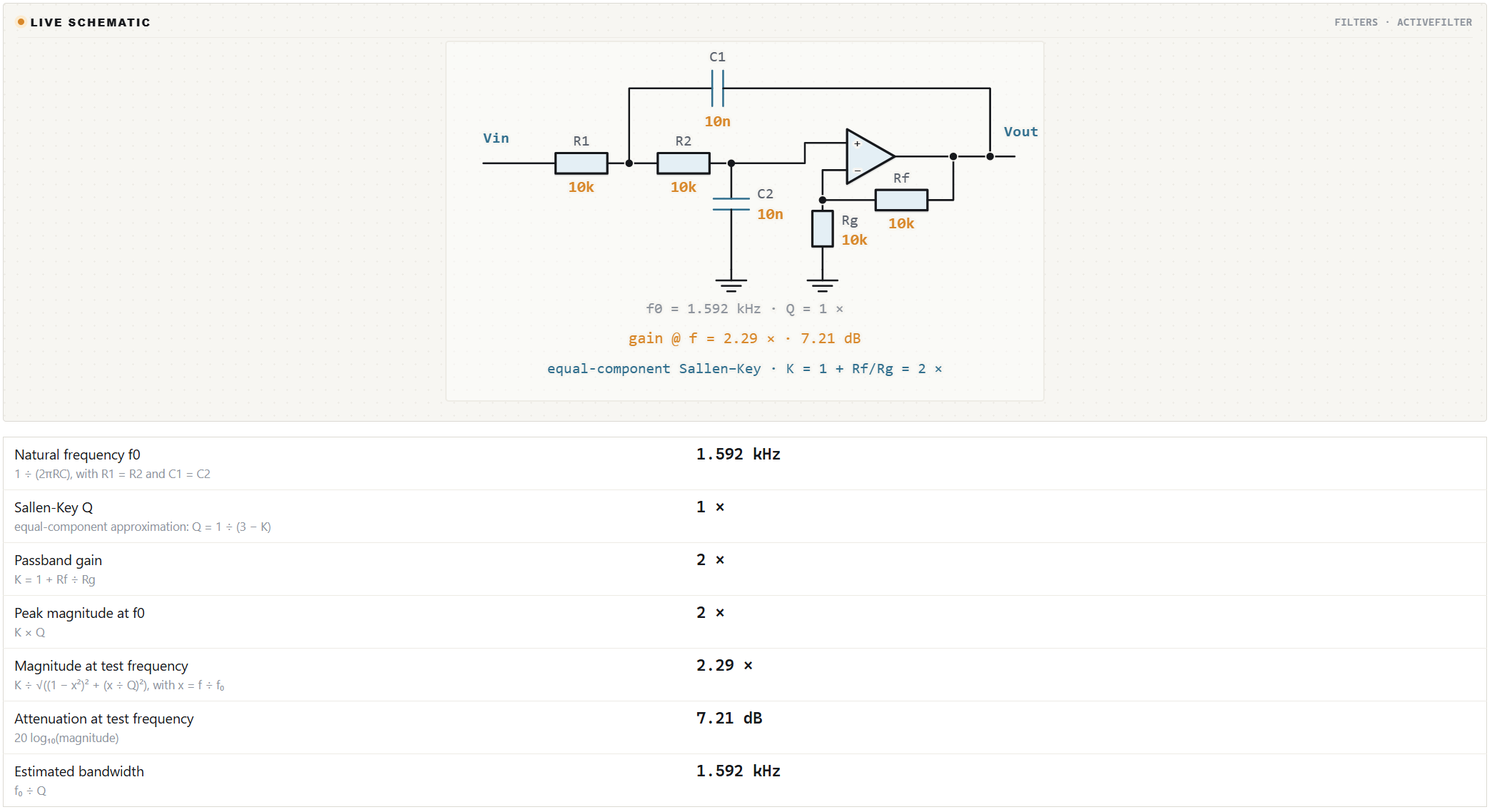 Every result says how it was worked out.
Under each number is the expression that produced it, and it follows your choices rather than being a fixed caption. The time-constant row reads R × C on an RC filter and L ÷ R on an RL one. The synchronous page assigns hard-switching loss to the high side in a buck and the low side in a boost. Ohm's law names the pair you actually entered and says nothing under the two you typed. 316 of 339 result rows carry one; the rest are values you entered, lookups, verdicts in prose, or the same number in another unit.
There are also 13 reference tables — E series, chip resistor sizes, ceramic and electrolytic capacitors, inductor core materials, diodes, zeners, LED forward voltage by die, TVS, packages with θJA and θJC, PCB laminates, AWG, batteries.
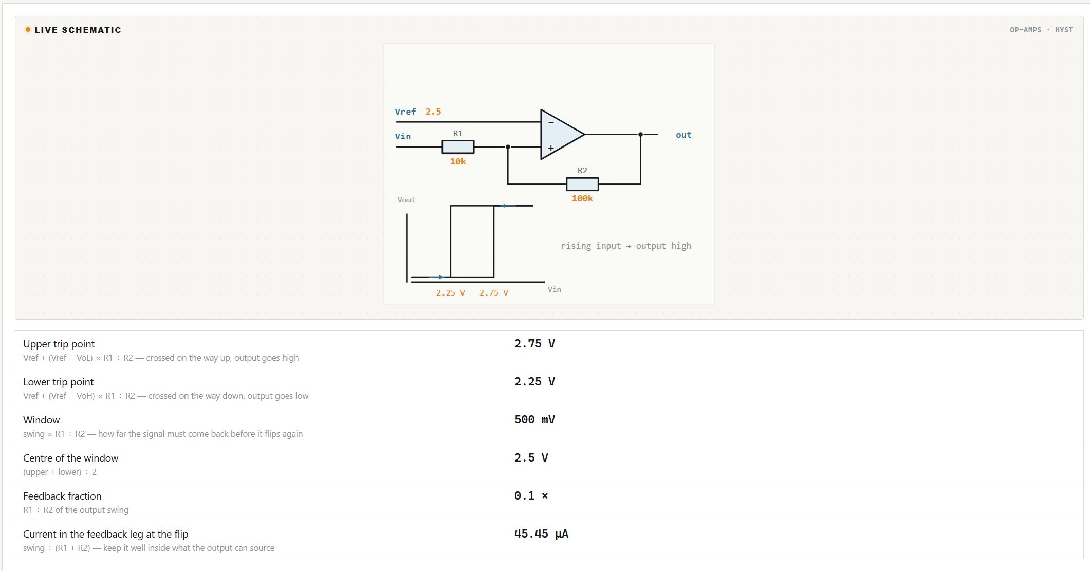
Some of the drawings plot behaviour rather than topology — the comparator draws its own hysteresis loop with the two trip points on it:
 Where it refuses to answer.
The same rule as the AWG table in the old thread, applied wider. The clearance and creepage section explains what actually indexes those tables — working voltage, internal or external, coated or not, pollution degree, material group — and then sends you to IPC-2221B Table 6-1 and IEC 60664-1 rather than reprinting millimetres I cannot verify. A safety figure remembered wrongly would be believed on a mains board. The MOSFET device library leaves a field empty where the datasheet publishes nothing rather than filling it with a plausible number, and says what the gap costs the estimate. Every θJA is stated as the datasheet's own test board in still air, with the reminder that once a heatsink is on it the figure is θJC + θCS + θSA and never θJA.
The tests.node test.jsNo dependencies, because the thing being tested has none either. The part I did not expect to earn its keep: it draws every option of every dropdown — 167 diagrams — and measures each for overlapping parts, wires passing through a part, labels crossed by a wire, labels printed too close together, and text outside the frame. That found six drawing faults nobody had seen by looking at the page, including an amplifier input that landed outside its own box and a return wire that ran straight through the ADC symbol.
There is also a mutation harness that puts each fixed fault back, one at a time, and checks the suite notices. Fifteen for fifteen. A test that cannot fail is not a test.
What it had wrong. A careful read of the formulas last week found four arithmetic errors, all of them shipped and none visible without checking:
- Gate-drive loss was being pushed through the MOSFET's thermal path while the note beside it correctly said the driver dissipates it. It counts against efficiency and not against Tj now — a 12 → 5 V at 3 A high-side estimate drops from 57.4 to 53.9 °C.
- The RLC band-stop phase was 180° out below resonance. The output is taken across L + C, so the numerator contributes ±90°, and atan2(R, X) alone returns the lower half of the sweep inverted. At f₀ the output is a null and the page now says the phase is undefined instead of printing one.
- A boost's ESR ripple used ΔIL, which is the buck case. A boost's output capacitor feeds the load alone while the switch is on and takes the whole inductor current when it opens, so the step across the ESR is the peak current. The figure was about three times optimistic.
- The π input filter's series capacitance was presented as a result when it is the high-impedance-source limit. It says so now.
None of the tests would have caught any of those. They check that the page is consistent with itself. Only somebody who knows the material can check that it is consistent with reality.
Please try to break it.That is the real reason for this post, and it is now quick to do. Because every figure shows the expression that produced it, checking one no longer means reading source. Open a calculator you know cold, put in numbers whose answer you already know, and check two separate things:
1. the number, and
2. whether the line underneath it describes what the number actually did.
Those are not the same check, and the difference is where the errors live. All four above passed the first and failed the second. The gate-drive note said the driver dissipates that loss while the arithmetic was pushing it through the junction. The band-stop phase looked entirely plausible until it was compared against jX / (R + jX) and the sign of the lower half of the sweep did not survive.
The reference tables deserve the same treatment and are the part I am least sure of: core Bsat and permeability by material, LED Vf by die chemistry, package θJA and θJC bands, the 1N47xx voltage list, the standard TVS stand-off voltages. Anything given as a class range is somewhere I could be wrong; anything given as a specific figure is somewhere I could be wrong in a way that matters more.
And if you think a refusal is wrong — that a number I declined to print is one I should have printed — say so. I would rather argue about that than quietly leave a hole.
Post the row and what it should be. No account, no install, nothing to clone; it opens in a tab. The four above were found exactly that way, in one sitting, by one person reading carefully — and I would far rather hear it here than have somebody size a shunt off a wrong number.
https://github.com/AJEngineering/circuit-calcs
 Home
 Help
 Search
 Login
 Register


