- You are aware that the voltage supervisor eats probably half of your energy budget?
I was worried about this and the TLV809E data-sheet https://www.ti.com/lit/ds/symlink/tlv809e.pdf shows a typical 250 nA supply current.
Ah, yeah, I was looking at the TLV809 with 9 µA--though the 250 nA is only typical and for 3.3 V, up to 1.2 µA for Vdd=6 V.
- You are aware that D2 leaks another quarter or so of your energy budget through R3/R4?
I am open to select a diode that is better from this perspective (does better means lower reverse leakage current?); do you have any suggestions?
Reverse leakage current is the datasheet number you are looking for, yeah. One I have lying around would be the BAV116T (5 nA max at room temperature), but no clue whether that's a good choice for your application.
- Are you sure that the MTS01Z doesn't have any ESD protection diodes on the I²C pins?
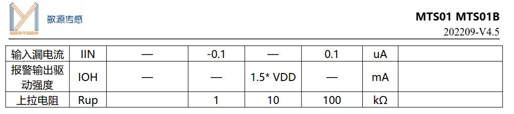
Not sure. The data-sheet https://www.lcsc.com/datasheet/lcsc_datasheet_2210121700_Mysentech-MTS01Z_C5197400.pdf shows max 100nA input leakage current.
Can I assume that there are no ESD protection diodes?
I can't read chinese, but other than that there is no indication there that there are no protection diodes. Ususally, such specs are under the condition that all other limits are observed, and typically, one limit would be something like VIH <= Vdd + 0.3V, which would be exceeded when Vdd is 0V and VIH is 5V. Now, in this case, the datasheet doesn't specify an upper limit for VIH, as far as I can tell. But that obviously can't be true (the chip certainly won't survive a sustained kilovolt applied to the pins), so we don't really know at what voltage those pins would not exceed 100 nA when powered down.
Also ... did you test that chip? I once tested a Mysentech DS18B20 clone, and that one wasn't great, though I don't remember details, IIRC quite a bit of offset from a genuine DS18B20+ from Maxim.


