Author Topic: No bitbanging necessary, or How to Drive a VGA Monitor on a PSoC 5LP w/Verilog  (Read 47685 times)

0 Members and 1 Guest are viewing this topic.

Offline miguelvpTopic starter

  • Super Contributor
  • ***
  • Posts: 5550
  • Country: us
Hi Miguel,
I'm the designer of a lot of flight controllers for multicopters and planes ( http://arsovtech.com/?page_id=1502   and   https://pixhawk.org/modules/pixracer ) but we suffer from lack of a good OSD for our video transmissions . All we have as an OSD is the old MAX7456....horrible, high current consuming chip, with just a character set. I'm thinking of a graphical OSD, which will give us more capabilities.
We have a frozen project using STM32F4xx MCU, but I think PSoCs are more flexible for the purpose.

It might be possible, not entirely sure. You could use an edge detect module and maybe if you can derive the pixel clock from the color burst or the signal is known, it could be done. I guess more information on the video signal would help.

Maybe send me details via PM?
 

Offline miguelvpTopic starter

  • Super Contributor
  • ***
  • Posts: 5550
  • Country: us
One more update (4th, but not completed since It's late)

But we have video now!


Using this test harness:


More details here (4th post):
https://www.eevblog.com/forum/projects/no-bitbanging-necessary-or-how-to-drive-a-vga-monitor-on-a-psoc-5lp-programmabl/msg825367/#msg825367
 

Offline CypressPSoC

  • Contributor
  • Posts: 46
Quote
And No, I don't get a commission from Cypress, not even free kits.
Write it up as an appnote and they might...

Thanks! didn't even think about that.

@Miguelvp - we're loving your projects with PSoC!
Write to me and I'd love to hook you up with free development boards and stuff...
I'll PM you my email address.
 

Offline miguelvpTopic starter

  • Super Contributor
  • ***
  • Posts: 5550
  • Country: us
Quote
And No, I don't get a commission from Cypress, not even free kits.
Write it up as an appnote and they might...

Thanks! didn't even think about that.

@Miguelvp - we're loving your projects with PSoC!
Write to me and I'd love to hook you up with free development boards and stuff...
I'll PM you my email address.


Thanks, sent you an email and a separate PM, was just kidding really about free kits, just wanted to let everyone know that yes I'm a fanboy but not because of perks.

Anyway, I'm leaving tomorrow to my in-laws in TX for Xmas, so I'm going to put this on hold until next year or maybe my wife's plans let me come back before new years.

I did make a new test harness, but had to change the IMO to 24MHz to avoid timing issues with the 6MHz more  precise one.
Not going to put it on the main thread because is just to show it can do individual 800x600@60Hz

With the Tutorial, it shouldn't be hard to figure out how implement what was added to this schematic for those following at home. (Edit: Although I did change the line_dma on the component from 16 to 1 because of the flip-flop takes one extra clock. Also for higher resolutions like 1024 visible, the horizontal counter has to be 11 bits instead of 10) but I think 800x600 is the best you can do with the internal oscillator.


And this is the output (I know, not even an interesting of a pattern, but it's displaying 800x600 individual pixels, of course not from a frame buffer)


Also I did try higher resolutions, but I would not push the pixel clock past 60MHz on the internal IMO. It looses lock easilly. I'll attach the OCXO soon.
« Last Edit: December 24, 2015, 07:43:43 am by miguelvp »
 

Online skench

  • Contributor
  • Posts: 19
  • Country: gb
Hi Miguelvp,

I found that to stop the timing violation messages I needed to change the device "Temperature Range" to the commercial setting of 0 to 85 instead of the default -40 to 85 C.

Regards
Stephen
 

Offline miguelvpTopic starter

  • Super Contributor
  • ***
  • Posts: 5550
  • Country: us
Hi Miguelvp,

I found that to stop the timing violation messages I needed to change the device "Temperature Range" to the commercial setting of 0 to 85 instead of the default -40 to 85 C.

Regards
Stephen

Thank you,

I'm going to be off the internet for a couple of days, but I'll resume when I get back.

Edit: btw, are you getting the same results?
« Last Edit: December 24, 2015, 04:10:49 pm by miguelvp »
 

Offline ale500

  • Frequent Contributor
  • **
  • Posts: 415
Awesome. I'll have a look at this chip, Maybe is it what I was looking for
 

Offline Carl47D

  • Newbie
  • Posts: 9
Awesome work!!!
Here´s a lot to read and learn about PSoC Verilog-based components.  :clap:
 

Offline miguelvpTopic starter

  • Super Contributor
  • ***
  • Posts: 5550
  • Country: us
Second half of reply #3 about using an external clock (optional) and showing the jitter of the internal IMO in comparison.
I updated the Zip file with archive05 in there but I'm attaching the extra support images in this post because of the file attachment limits, but embedded the images in the post.

https://www.eevblog.com/forum/projects/no-bitbanging-necessary-or-how-to-drive-a-vga-monitor-on-a-psoc-5lp-programmabl/msg825367/#msg825367

The half update starts at:
------------------------------------------------------------------------------------------------------------------------------------------------------
External clock
Optional: Using DSI Signal as a precise Clock Input


Edit: I've seen VHDL components in the Cypress made components, so even if only Verilog seems to be supported officially, their Warp synthesizer might be able to handle VHDL. I'm just noting this for future research since I do prefer VHDL if I had the choice.

Edit: also I changed the operating temperature range from industrial to comercial, thanks Stephen a.k.a. skench for looking into that!.
« Last Edit: December 28, 2015, 07:19:39 am by miguelvp »
 

Offline alanambrose

  • Frequent Contributor
  • **
  • Posts: 377
  • Country: gb
Just to say thanks Miguel, this is a very nice thread. I think quite a few people have been wanting to take their first steps in fpga/verilog.

Can I ask - in you opinion, would it be possible for the studious follower of the thread to figure out how to go on to support say hdmi or dvi?

Regards, Alan
“A foolish consistency is the hobgoblin of little minds"
 

Offline miguelvpTopic starter

  • Super Contributor
  • ***
  • Posts: 5550
  • Country: us
Can I ask - in you opinion, would it be possible for the studious follower of the thread to figure out how to go on to support say hdmi or dvi?

Regards, Alan
I'm afraid HDMI or DVI might require external hardware.

The Analog portion could be used for getting a differential signal and the chip is capable to meet the minimal 25MHz clock generation. The problem is the TMDS encoding, it uses 10 bits for each 8 bits of data, meaning that we will have to spew the actual pixel data at around 250MHz. Maybe there are some HDMI modes that require less bits reducing the number of color but I have not look at that in any detail, but even if we reduce them it's probably going to need over the 80MHz this chip can do. HDMI black and white might be possible, even any two colors.

But with an HDMI TX chip it should be possible to drive it with the PSoC.

Edit: this is a good potential HDMI TX candidate, but I will think you'll need an XTAL or something that can generate a clock more stable than the PSoC IMO.

http://www.analog.com/en/products/audio-video/analoghdmidvi-interfaces/analog-hdmidvi-display-interfaces/adv7525.html#product-overview

You'll have to make sure the video and audio signals you feed from the PSoC to the HDMI_TX are within the 3.3V logic levels. That's is configurable on the PSoC, but might require a 2nd power rail on VDDIO set to 3.3V.

One last think, it seems to source them in low quantities you'll need to go the aliexpress way, plus spin your own board because the EVAL-ADV7525 is cost prohibited. Maybe not worth it to go this way unless you can find some HDMI_TX board already made.

Edit again, this link might help:
http://www.analog.com/library/analogDialogue/archives/47-02/HDMI_VGA.html
« Last Edit: December 28, 2015, 07:38:45 pm by miguelvp »
 

Offline miguelvpTopic starter

  • Super Contributor
  • ***
  • Posts: 5550
  • Country: us
Implemented the frame buffer, the DMA transfer


Not too happy with the result since the internal clock is not enough, os I had to use the OCXO to get the monitor to lock into the video. I'll try to figure out why at a later point, but needed to post this instead of delaying things.
Also other issues came up, that will be addressed later as well.

4th Update can be found here (reply number 4):
https://www.eevblog.com/forum/projects/no-bitbanging-necessary-or-how-to-drive-a-vga-monitor-on-a-psoc-5lp-programmabl/msg825368/#msg825368

Edit: Next installment will be adding the EEPROM character set so we can display something more exciting :)
Hopefully this week or this coming weekend at most. Doing the actual project doesn't take too much time, but documenting it and explaining the steps takes a lot off time.

Edit: Also this is just black and white for now (well that upper middle MUX decides the colors 0x0 for the background and 0xf for the foreground) at a later date we will add some color buffer per character. But you can change those constants to any two colors.
« Last Edit: January 04, 2016, 03:33:03 am by miguelvp »
 

Offline miguelvpTopic starter

  • Super Contributor
  • ***
  • Posts: 5550
  • Country: us
Part 5 (EEPROM character set) is done and solved some timing issues.
Still using the OCXO and I'll do that on part 6, where I will attempt to use the UDBs and Datapaths within Verilog to optimize timings and usage of resources, and shuffle things around for the remaining tasks.

This is just half of post 5, I'll add some other things in a 2nd half of the post.

Link here (Post 5 I believe):
https://www.eevblog.com/forum/projects/no-bitbanging-necessary-or-how-to-drive-a-vga-monitor-on-a-psoc-5lp-programmabl/msg825369/#msg825369

Current result:


1st character is off, I will address that on the 2nd half of the post to come soon.
 

Offline miguelvpTopic starter

  • Super Contributor
  • ***
  • Posts: 5550
  • Country: us
Fixed the memcpy by only copying part of the frame per refresh 1/10th at a time so it takes 10 frames to update the DMA buffer giving us just a mere 6fps at the CPU level, the video is still 60fps from the DMA buffer to the display though.

I don't know if anyone is following this anymore but I'll keep on updating since its still getting views.

Update is at the bottom of the previous post:
https://www.eevblog.com/forum/projects/no-bitbanging-necessary-or-how-to-drive-a-vga-monitor-on-a-psoc-5lp-programmabl/msg825369/#msg825369

After -- Continuation

The DMA memory to memory is coded, and it was partially working but now it's broken. I probably messed up the TD chain but I'll fix it at a later time, that should help get back to 60 fps.

I added code to actually change the buffer while is not refreshing so it's a little more dynamic than just a mere static frame buffer.
It's just inverting characters and not the grid to demonstrate the frame buffer is working.


This is what is doing when the loop is not busy refreshing the screen.
Code: [Select]
            // For fun lets flip a character of the frame buffer
            // while we are idle at 2fps (every 30 frames),
            // our current update rate is 6fps (every 10 frames) so its divisable.
            if (frame == 10)
            {
                // Reset the frame counter.
                frame = 0;
                // Flip the current character 8x8 bits
                for (n=0; n<8; n++)
                {
                    cframe[y+n][x] = ~cframe[y+n][x];
                }
                // Update our x and y values for the next loop
                // Only do the characters not the grid so skip every other character.
                x = x+2;
                if (x >= VGA_X_BYTES)
                {
                    // We reached the end of the line so reset the column to 0
                    x = 0;
                    // Increase the row by two characters (16 pixels)
                    y += 16;
                    // Adjust for our last half character since we don't want to get past the buffer
                    // The -4 is specific code for the 100x37.5 (800x600) mode
                    if (y >= VGA_Y_BYTES-4)
                    {
                        y = 8;
                    }
                }
            }

Edit: I did fix the timings as well so we get the full frame as expected, with nothing cutting off the edges.
Edit2: found what was wrong with the DMA memory copy, actually many things, using DMA__ instead of DMA_MEM__
so it was overriding my other DMA channel, also I needed to preallocate all of the transaction descriptors beforehand.
Forgot to add the CPU trigger and right now I'm trying to figure out why it doesn't reach the end of the chain to trigger the interrupt. But I'm getting there.
« Last Edit: January 11, 2016, 04:53:34 am by miguelvp »
 

Offline miguelvpTopic starter

  • Super Contributor
  • ***
  • Posts: 5550
  • Country: us
Fixed the DMA memory copy.
We can change the CPU buffer at 60 fps, that is if you can do much in 16.667 ms minus the time it takes to refresh the screen.
Still plenty of time for a lot of things since that is 666,666.7 clock ticks per frame at 40MHz CPU clock and 60Hz frame rate.

The refresh fits during the vertical retrace (28 lines out of 628 lines total) so we have at least 636,942.7 CPU cycles left when it's not refreshing because the DMA copy is probably less than the 28 lines required.
That means we have at least 15.924 ms left out of the 16.667 per frame to do things to the CPU frame buffer.

Edit: 800x600@60Hz with 60fps update time from the CPU on a small Cortex M3 MCU on a $10 dev kit is pretty cool IMHO.

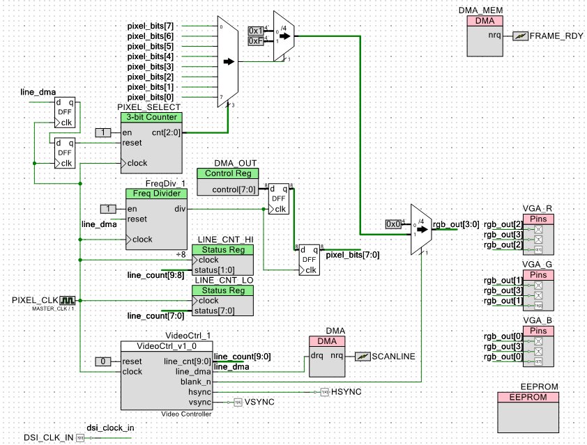
Current schematic so far:


Added the archive on that post (archive 09) and also included the main.c as an attachment (DMAmain.c)

Next the Verilog optimization using the UDBs and Datapaths to make it even more resource efficient and hopefully allowing us to go back to the internal oscillator instead of the OCXO

Edit: the Verilog optimization might take a while because explaining how the UDBs and Datapath work is going to take a lot of explanation, but I'll try to keep it concise.

Edit again, since the MCU can handle 80MHz I could derive that by halving the PIXEL_CLK by 2 and doubling the number of ticks we have to spare when it's not refreshing. Problem is that I want to target the internal IMO so we can't hit 80MHz, but there is still plenty of room for improvement, with the OCXO we can double the performance FWIW since we are at just 50% of what the MCU can do.

Edit again once more: with the MCU at 80MHz at 800x600@60Hz our idle time would be 1,273,885 cycles on idle time, maybe better since the DMA memory copy would take less than the 26 lines frame time. This chip really rocks!
I do wish that the PLL derived clocks were separate, meaning that we could bias the digital clock by 2 and leave the CPU clock at full 80MHz but there are ways around that as well.


« Last Edit: January 11, 2016, 09:06:36 am by miguelvp »
 

Offline miguelvpTopic starter

  • Super Contributor
  • ***
  • Posts: 5550
  • Country: us
I guess the question at hand, should I keep going? or is that enough to expose what this chip can do?

If you are a casual, then register and at least tell me to keep on doing this, if you are a regular give me some feedback. It's not my site after all anyways.

I think I already exposed many features on this chip, but there is still plenty to cover.

I will most likely still do this until completion but the rest is a bit boring so not sure if it's worth the effort.

I'm just asking for a little feedback.

Edit: after 6 updates without a response I'm inclined to just move on to a different project, since in my mind, this is done and I'm just polishing the hard edges. I will still finish it but just publish the results without explanation, and I think that might be the best unless it's worthy to be so wordy.
« Last Edit: January 11, 2016, 10:34:49 am by miguelvp »
 

Offline deephaven

  • Frequent Contributor
  • **
  • Posts: 796
  • Country: gb
  • Civilization is just one big bootstrap
    • Deephaven Ltd
I've been following your progress with interest. Not many people here go into such in-depth details of their projects. This is a great reference for anyone wanting to embark on using the PSoC stuff and it could well encourage other people to have a go. It's certainly an amazingly low price point. So, yes, if you have the time to continue the write-up please do so. I'm sure there are a lot of silent readers out there!
 

Online skench

  • Contributor
  • Posts: 19
  • Country: gb
I can only second what deephaven has said.
 

Offline miguelvpTopic starter

  • Super Contributor
  • ***
  • Posts: 5550
  • Country: us
Cool, thanks, then moving along I'll go for the UDB and Datapaths this week.

It should reduce the number of resources we are using.

Also, according to my calculations, we have at least 95.5% of the CPU left idling.
« Last Edit: January 11, 2016, 04:33:01 pm by miguelvp »
 

Offline OrangeWindies

  • Newbie
  • Posts: 1
  • Country: se
I guess the question at hand, should I keep going? or is that enough to expose what this chip can do?

If you are a casual, then register and at least tell me to keep on doing this, if you are a regular give me some feedback.

I've registered just to give you some feedback. You should definitely keep going.

Your project inspired me to do something similar with composite video output on a PSoC 5LP. I'm looking forward to the UDB and datapath optimisation as I'm pretty sure that my implementation (I've never written Verilog before) is pretty sub-optimal.
 

Offline miguelvpTopic starter

  • Super Contributor
  • ***
  • Posts: 5550
  • Country: us
Thanks,

I'm pretty much done with my research on how to approach this, I might be able to fit it in just 2 UDB Datapaths out of the 24 the 5LP has, meaning this could even fit in a PSoC 4 or I'll aim for that.
 

Offline miguelvpTopic starter

  • Super Contributor
  • ***
  • Posts: 5550
  • Country: us
Most of the UDB Datapath work finished, but I'll have to finish it tomorrow (or soon)
I'm not placing the whole project anymore, because the new modules is equivalent to the old one (other than more efficient)

At this state it has not replaced our original one yet and we might need to revise the untested Verilog.

For those curious, this is a depiction of a UDB Datapath with its ALU


Link to update:
https://www.eevblog.com/forum/projects/no-bitbanging-necessary-or-how-to-drive-a-vga-monitor-on-a-psoc-5lp-programmabl/msg825370/#msg825370
 

Offline miguelvpTopic starter

  • Super Contributor
  • ***
  • Posts: 5550
  • Country: us
Well, finished implementing the UDB based component but it's not working, but I'm updating the progress anyways.

https://www.eevblog.com/forum/projects/no-bitbanging-necessary-or-how-to-drive-a-vga-monitor-on-a-psoc-5lp-programmabl/msg825371/#msg825371

I'll try to see if I can fix it, or if it makes more sense to move on since our previous version works fine.
Or maybe I'll use the UDB Editor instead of the Datapath editor directly and draw the state machine since that should be easier and less error prone.

At least it shows how to make a new component version that you can update or use the previous version


Offline miguelvpTopic starter

  • Super Contributor
  • ***
  • Posts: 5550
  • Country: us
For those that want more information, there is a huge PSoC 5LP Architecture Technical Reference Manual that complements the datasheet and covers all kinds of details.

http://www.cypress.com/documentation/technical-reference-manuals/psoc-5lp-architecture-trm

And then there is a pretty hard to navigate PSoC® 5LP Registers TRM (Technical Reference Manual) that describes pretty much all available registers (most boring unless you are looking for some specific register to do something that is not really accessible by Creator)

http://www.cypress.com/documentation/technical-reference-manuals/psoc-5lp-registers-trm-technical-reference-manual
 

Offline miguelvpTopic starter

  • Super Contributor
  • ***
  • Posts: 5550
  • Country: us
End of the project, I'm under using the DMA capabilities and I have to re-structure the whole thing so we can do multiple synchronous DMA transfers that don't interfere with our transfers from the higher memory to screen.

During the vertical retrace we do transfer the whole frame buffer in 64 byte bursts, that's is a more efficient transfer than wasting 8 clock cycles for one byte to draw 8 pixels. Any other transfers on that DMA spoke will cause contention that will manifest on what you see in the screen.

So a new iteration is needed, but documenting all that would take too much time.

https://www.eevblog.com/forum/projects/no-bitbanging-necessary-or-how-to-drive-a-vga-monitor-on-a-psoc-5lp-programmabl/msg825372/#msg825372

In any event, what it's there so far is pretty useful as it is and the whole purpose of the tutorial was to show how to use Verilog on this affordable chip.

Synchronous DMA transfers over a 32 bit channel is beyond what I want to get into, but our simple 8 bit transfers are only using 25% of the real bandwidth and we are only taxing the system by 50% of it's capabilities. So a lot more is posible but time consuming to explain.

I hope I left behind plenty of information to get you started and looking into how to improve it on your own.

I'm going to do one more post using just the component we created here to make a simple scope but without using the frame buffers and directly drawing the scope signals by hardware to demonstrate that aspect of things.

I'll work on that this coming weekend.

After all we ended up being able to display a full 800x600 frame buffer at 60Hz with alphanumeric text and the CPU is free for 95.5% of the time to do things on that frame buffer as long as it doesn't involve more DMA channels, which are needed for the rest of the planned steps.

But there is a lot of optimizations that can be done. The 7 cycle setup time is a one off, after that you can push one byte per clock cycle allowing more bandwidth with the proper chaining and priorities on the other synchronous transfers without contention.

I do hope you got something out of this long tutorial.


Share me

Digg  Facebook  SlashDot  Delicious  Technorati  Twitter  Google  Yahoo
Smf