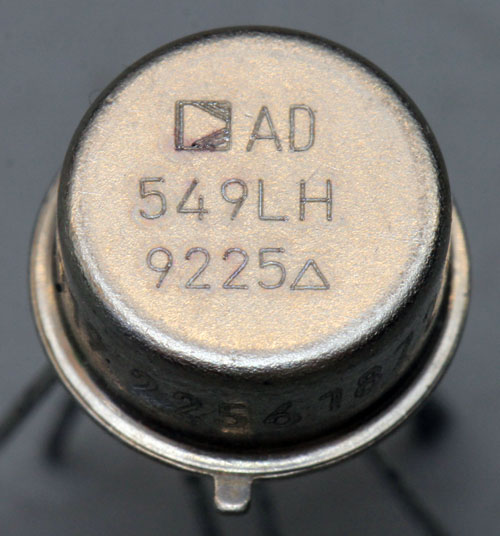
The AD549 is a so-called electrometer opamp. These are opamps with extremely low input currents. In the best bin with index L, the typical input current is just 40fA regardless of the common mode voltage. This corresponds to just one electron every four microseconds. Up to the maximum operating temperature of 70°C this current rises sharply as usual, but remains below 2,8pA.
The typical offset voltage is 0,3mV and can increase up to 0,9mV at high temperatures. The bandwidth is 1MHz, the slew rate 3V/µs.
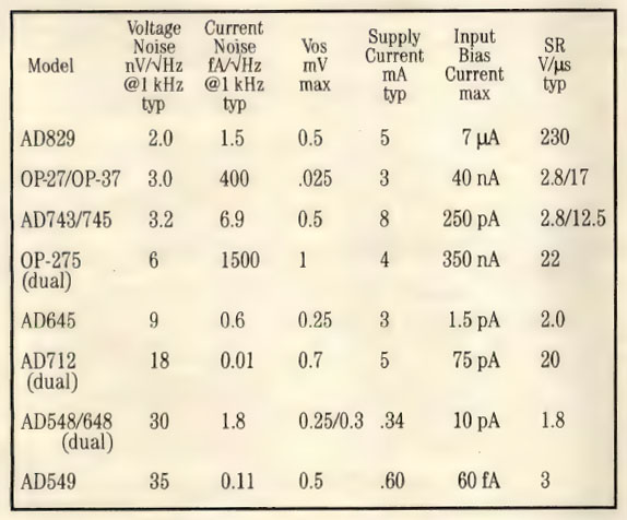
A 1992 Analog Devices advertisement compares the AD549's specifications to other low-noise op amps. The bias current of the AD549 stands out especially. It is by far the lowest of all types.

Analog Devices achieves the extremely low input current with the so-called "Topgate JFET Technology". The datasheet refers to the patent US5319227 "Low-leakage JFET having increased top gate doping concentration". This patent describes a special JFET and contains the above figure, which has been colored here for better understanding.
Much of the leakage current of an ordinary JFET occurs at the large interface between the gate and the substrate. In the top-gate JFET described in the patent, the upper part of the gate is isolated from the lower part. As will be shown, the input signal of the AD549 is connected only to the upper part of the gate. The small area and isolation from the substrate significantly reduces leakage current.
The package provides a guard pin that is only connected to the housing. If you do not want to increase the low input currents of the AD549 excessively by leakage currents, you have to surround the input potentials with shields which carry the same potential. This applies to the housing but also and especially to the circuit board. It is even better not to build the critical input pin with the input circuitry on the board at all, but to construct it on highly insulating spacers.
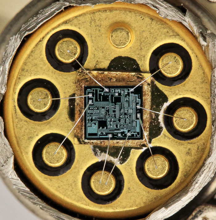
The negative supply potential is led to the die with two bondwires.
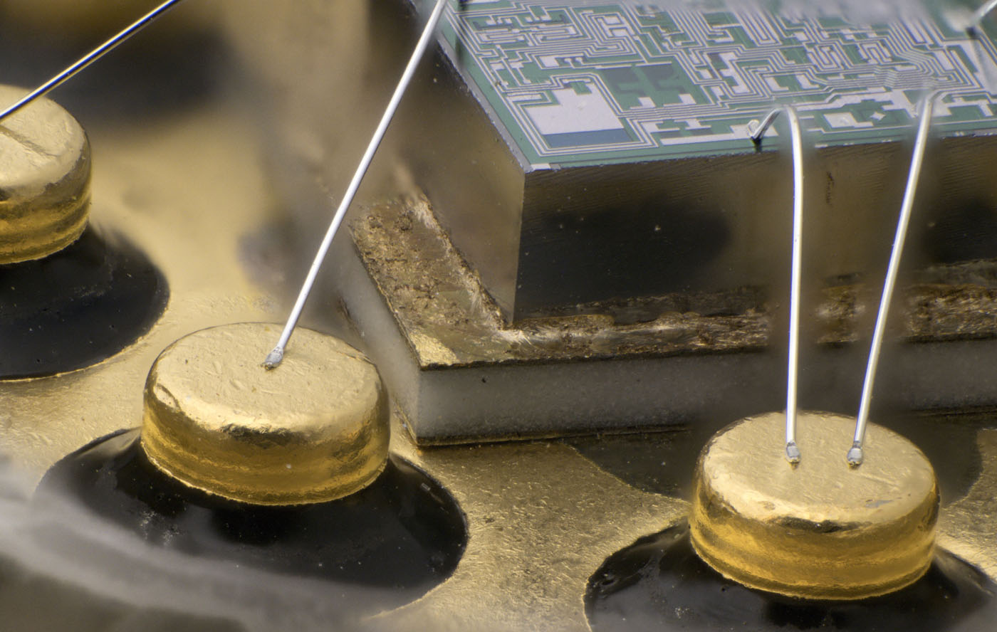
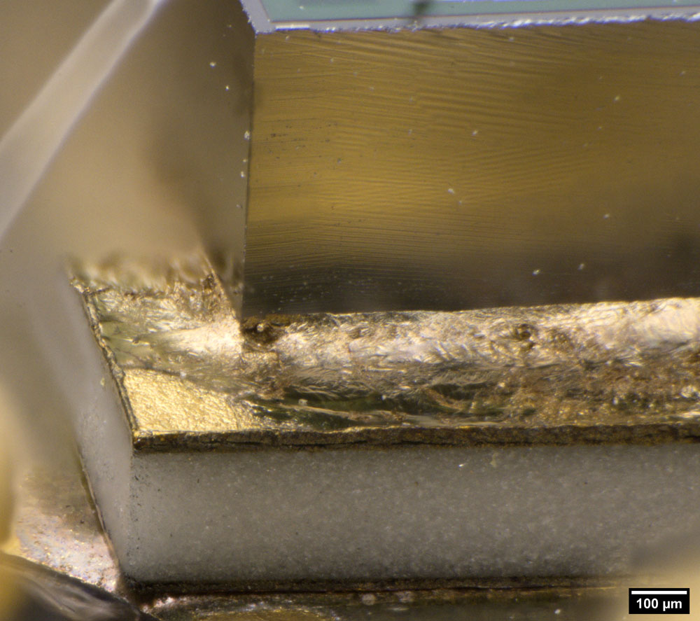
Since the guard potential is applied to the housing, the die must be isolated from the housing with a ceramic carrier.
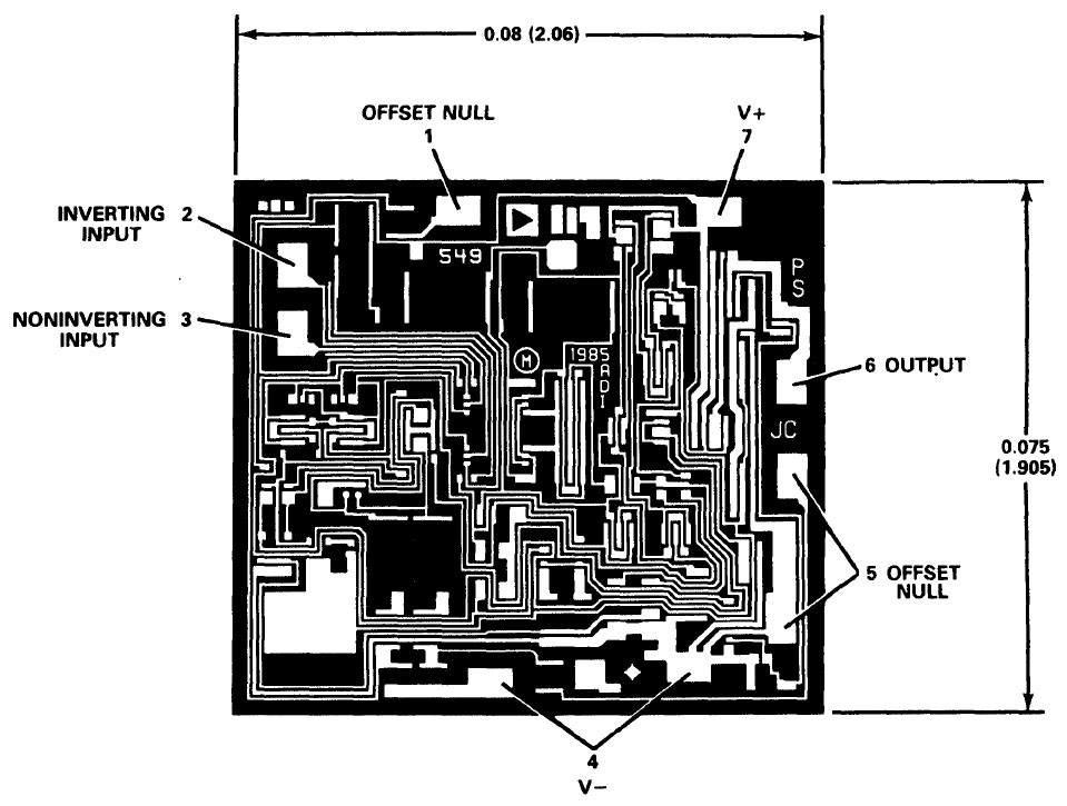
Older versions of the datasheet contain an image of the metal layer. The dimensions of the die are therefore 2,06mm x 1,905mm.
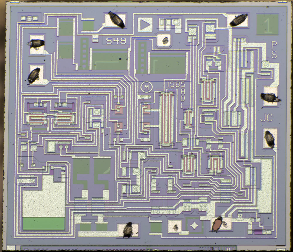
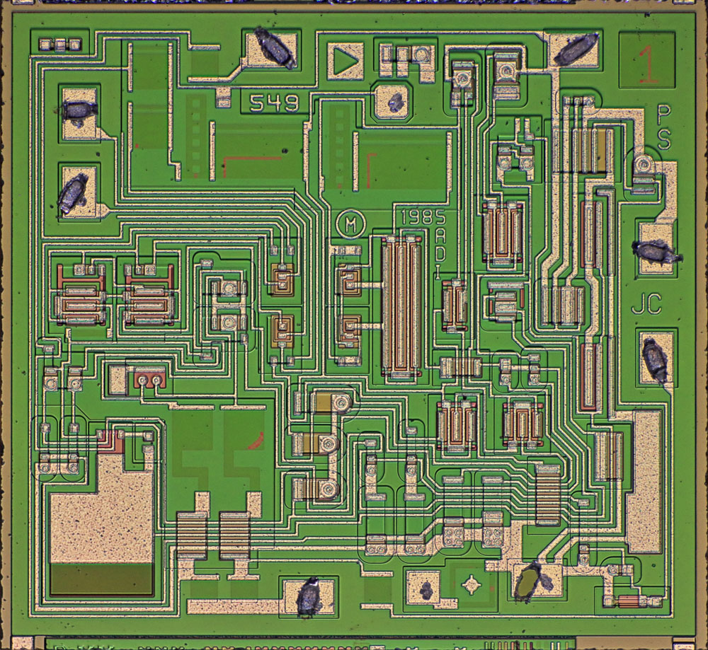
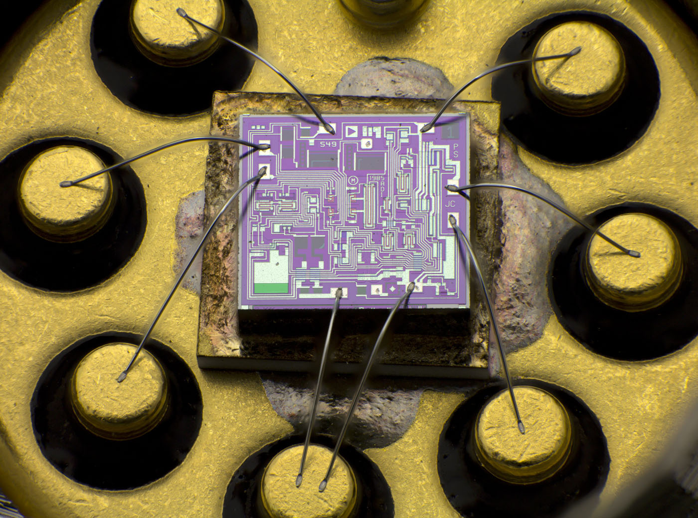
On the die there is the designation 549 and twice two letters that could be abbreviations of the developers. The design dates back to 1985.
Several resistors were calibrated with a laser. Typical for Analog Devices, there is a square with a testpad on the lower edge that is used to adjust the laser process and the number 1 is engraved in the upper right corner.
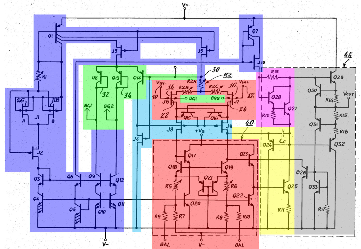
The datasheet of the AD549 does not contain a circuit diagram. However, it refers to the patent US4639683, which describes the above opamp. As will be shown, the schematic shown there matches the circuit in the AD549 except for one small detail. For better understanding, the individual function blocks have been colored.
The red block is the differential amplifier at the input of the OP549. The JFETs J6/J7 are the input transistors. They each have two gate terminals, of which just the top gate is connected to the respective input. The differential amplifier has its own V- potential. The double transistor Q21 guarantees that the potentials in this part of the circuit never rise too high. The transistors Q18/Q19 represent a current mirror with which the input transistors operate. Q17 generates the base current of the current mirror. Transistor Q23 forms the output of the differential amplifier with current sink Q22. Current sink Q20 appears to have been inserted in the left path to keep the circuit as symmetrical as possible.
Transistors Q15/Q16 probably reduce saturation effects when the input stage is overdriven. In this case, they open the cascode transistors J8/J9 (cyan), which otherwise shield the input transistors from the effects of common mode voltages.
The bias setting (blue) is relatively complex. It is based on the two JFETs J1A and J1B with resistor R1. The reference current generated across them is distributed to the circuit parts under J3 and J5 by transistor Q1. The cascode circuit with the JFETs isolates the current sources from voltage fluctuations. The reference current is further multiplied in the lower half by transistors Q3-Q6 and Q9-Q12.
Resistor R2A is balanced so that, in combination with the reference current, the same potential is present at testpad 30 as at the front gates of J6 and J7. Via transistors Q8/Q13/Q14 (green) this potential is transferred to the respective back gates. This ensures that front gate and back gate always have the same potential.
The input amplifier controls the voltage amplifier stage (yellow), which in turn controls the output stage (gray). The quiescent current setting (purple) reduces the crossover distortion. The power amplifier is supplied by its own current mirror consisting of Q7 and J10. Q30 and Q31 protect the output stage from too high currents. An overcurrent on the lowside does not directly reduce its output level, but the drive of the voltage amplifier stage.
An important point of the circuit is the adjustment. First, using resistor R1, the current through J1A/J1B is set to the value at which the temperature coefficient of the JFETs becomes minimum. Then R2A is adjusted so that the potential at point 30 is the same as at the front gates, i.e. the inputs of the AD549. This is necessary to get the same potential at the back-gates as at the front-gates. The JFETs J1A/J1B are constructed in the same way as the input transistors J6/J7. This ensures that production variations and drift effects affect both transistor pairs very similarly.
After the adjustment of the bias, the offset voltage and temperature drift of the input stage are adjusted. The resistors R5/R6 define the distribution of the currents to the two input transistors. Since the temperature drift of the JFETs depends on the drain current, the temperature drift of the offset voltage can be adjusted via this resistors. For this reason, it is not ideal for a JFET differential amplifier to adjust the offset voltage via the ratio of the drain currents, since this simultaneously changes the temperature drift of the offset voltage. Instead, the offset voltage of the AD549 is adjusted with the source resistors R2B/R2C. Because there is no easy way to vary the source resistors externally, the external offset adjustment is still done via the current distribution in the two branches. Accordingly, the datasheet indicates an additional temperature drift of up to 2,4µV/°C per adjusted millivolt of offset voltage.
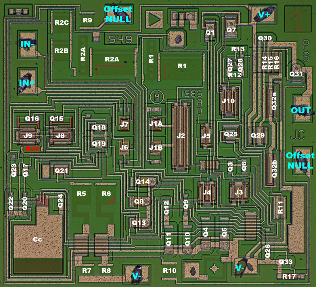
On the die all components from the schematic of the patent can be found. Just the resistor RJ9 is a small deviation. This resistor is located in the drain connection of the cascode JFET J9. It is from this branch of the differential amplifier that the signal is decoupled to the voltage amplifier stage. The resistor was obviously inserted quite deliberately. The purpose of the resistor remains unclear.
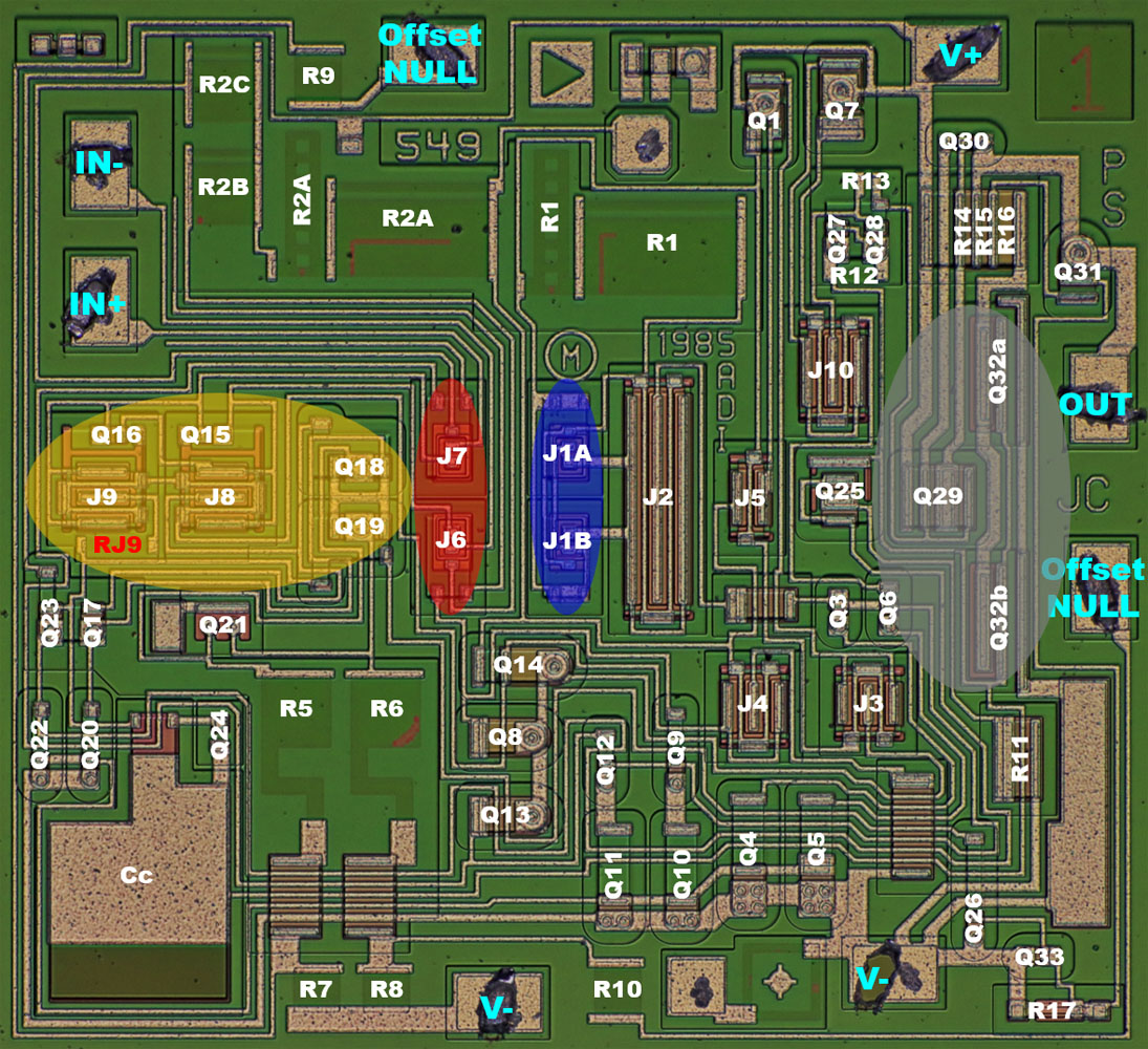
The JFETs in the input amplifier of the AD549 are located in the center (red). Directly next to them, the JFETs of the reference path are integrated (blue). The arrangement around the horizontal symmetry axis of the die reduces the effects of thermal gradients, which are generated to a large extent by the output stage (gray). There, the lowside transistor has been split into two transistors and arranged around the highside transistor. This measure guarantees that independent of the load of highside and lowside the power dissipation always occurs symmetrically around the horizontal symmetry axis of the die. The remaining critical transistors of the input amplifier are arranged on the symmetry axis too (yellow).
The two JFETs at the input of the differential amplifier and the two JFETs in the reference path are integrated so that they behave as equally as possible. A further improvement could only be achieved by splitting and cross-connecting the transistors, but this would increase the area of the input transistors too, which would then again have a negative effect on the leakage currents and parasitic capacitances.
Having the operating current of the JFETs set by identical JFETs is extremely advantageous. David Fullagar describes in the widely cited article "Better understanding of FET operation yields viable monolithic J-FET op amp" that production variations cause the drain current Idss of integrated JFETs to drift by a factor of 9. Accordingly, it is difficult to define an ideal operating current in a design.
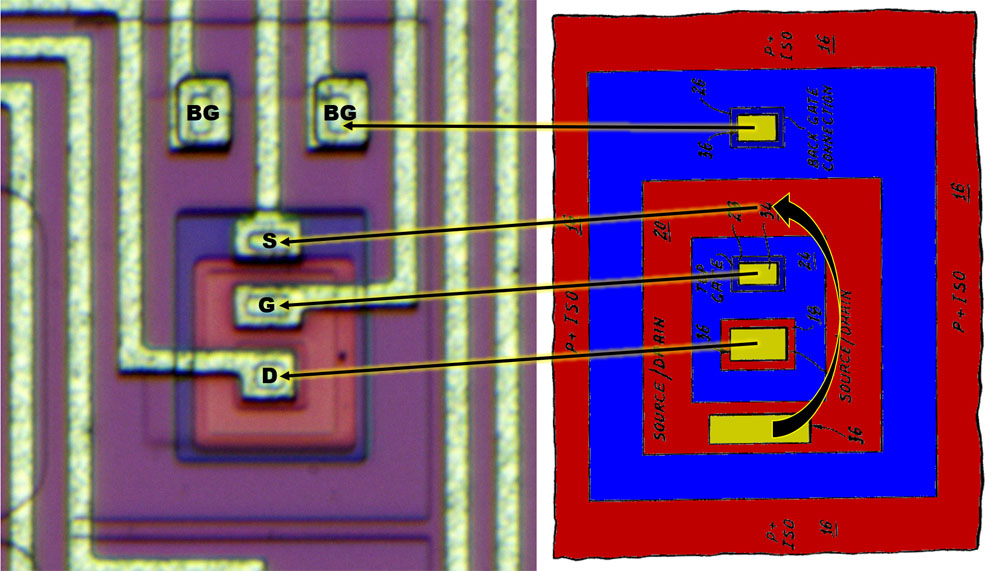
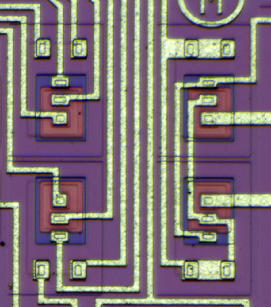
If you compare the structures with the patent US5319227, the parallels are easy to see. Just the source contact is not on the outside in the AD549, but between the top-gate and the back-gate connection.
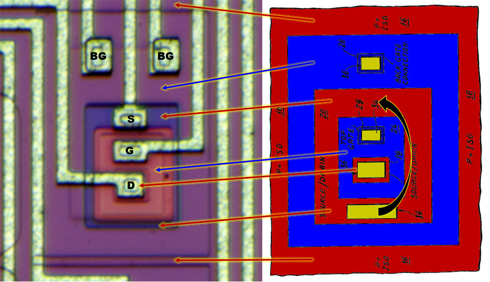
The structures cannot be immediately assigned at first glance. This is mainly due to the fact that the colors on the die are partly inverse to the usual colors for n- and p-doping.
The outermost square frame is the boundary between the n-doped well and the heavily p-doped insulating layer surrounding the transistor. The n-doped well carries the potential of the back gate.
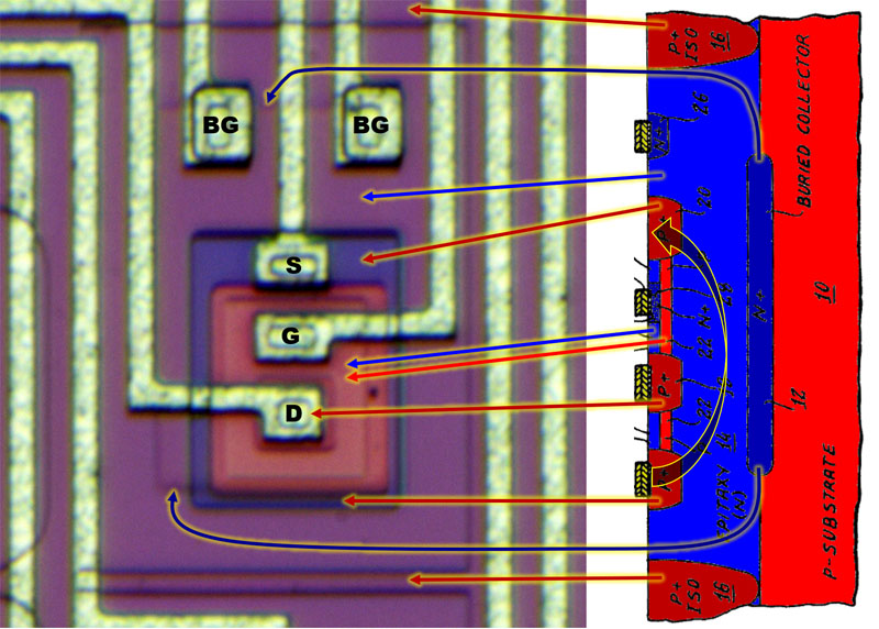
The dark blue frame contains the strong p-doping, which is the larger, outer source electrode. Below the center drain contact is the same doping, but it is hidden by the metal layer.
The red area is the n-doped top gate. Below it is the channel between source and drain. At the transitions from the red gate area to source and drain, a kind of frame can be seen. Probably there the gate area overlaps the highly doped contacts to the actual channel. So you can be sure that the channel is completely covered by the gate.
The buried layer with its strong n-doping, which is used as a collector feed line in NPN transistors, is just visible as a step in the surface.
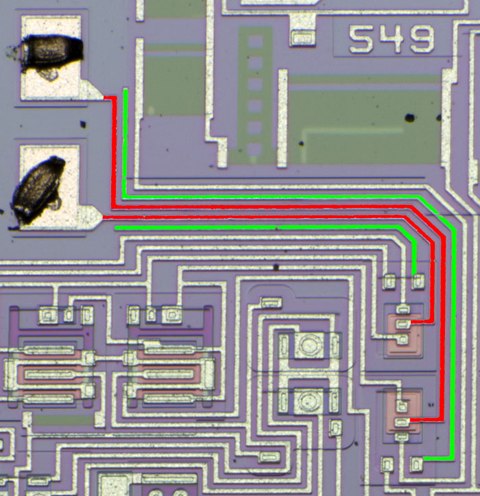
The two lines from the inputs of the AD549 to the JFETs of the differential amplifier (red) are shielded with the potentials of the back-gates (green). This reduces the parasitic capacitances and probably also the leakage currents to some extent.
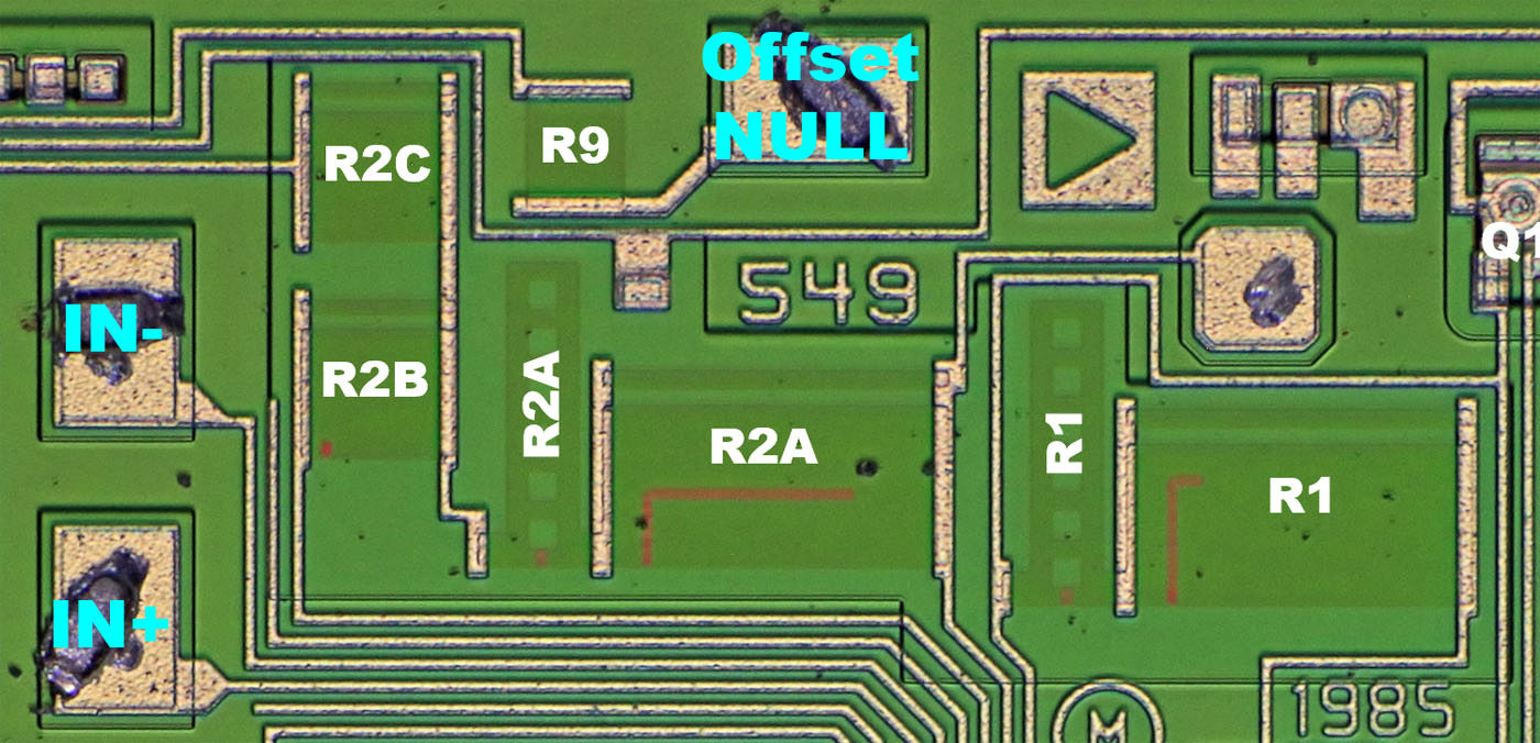
Resistors R1 and R2A each consist of two elements that allow more extensive adjustment. A test point allows to measure the potential above resistor R2, which is necessary to adjust the synchronization of reference current source and input stage.
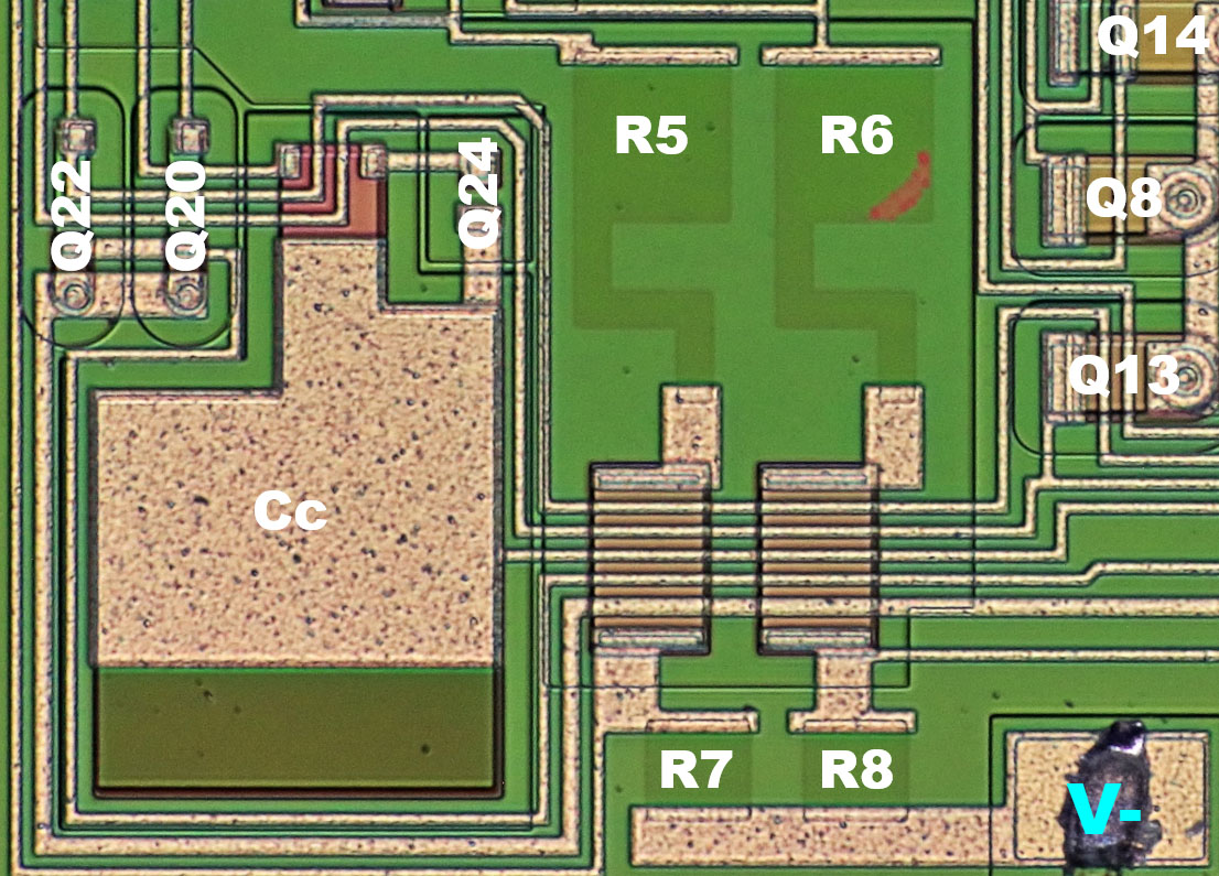
The resistors R5/R6, which are used to adjust the offset drift, provide a less complex structure. The traces of the adjustment are clearly visible.
The design offers the possibility to increase the capacitor Cc and thus adjust the frequency response.

The bipolar transistors Q15 and Q18 are directly integrated into the structures of the JFETs J9 and J8.
https://www.richis-lab.de/Opamp61.htm 


