Author Topic: Optocoupler with DC-DC converter and regulator in a board with chassis  (Read 9588 times)

0 Members and 1 Guest are viewing this topic.

Offline loop123Topic starter

  • Frequent Contributor
  • **
  • !
  • Posts: 297
  • Country: ca

I need an Optocoupler with DC-DC converter and regulator in a board or with chassis (with everything built in).

It has to pass 1mV from 0 to at least 20,000Hz (2 differential inputs and common/ground, 1 channel is ok) with no ripples or distortions or noise. 

Usually what noises are present in optocouplers?

It needs DC-DC converter with output to the Optocoupler with less than 5mA and regulator to power the DC-DC converter.

Have you seen any finished product like this? If not, and need to build it. What components of best quality must one need?

I don't have much experience soldering so prefer a ready made product or you make me one (and I'll pay you for the service, thanks).
 

Offline Andy Chee

  • Frequent Contributor
  • **
  • Posts: 688
  • Country: au
Re: Optocoupler with DC-DC converter and regulator in a board with chassis
« Reply #1 on: February 08, 2024, 01:23:58 am »
There may be a finished product.  What is your intended purpose?
 

Online moffy

  • Super Contributor
  • ***
  • Posts: 1749
  • Country: au
Re: Optocoupler with DC-DC converter and regulator in a board with chassis
« Reply #2 on: February 08, 2024, 01:40:28 am »
It has to pass 1mV from 0 to at least 20,000Hz (2 differential inputs and common/ground, 1 channel is ok) with no ripples or distortions or noise. 

Sounds like an audio application, moving coil mic or phono cartridge? Optocouplers are not noted for their low distortion, they also have gain drift issues hence they are typically used in digital applications. They are often used for feedback purposes in DC/DC converters but the comparison is done on one side and the error transmitted to the other so linearity is less of an issue. The best example of a linear optocoupler is the IL300: https://www.vishay.com/docs/83622/il300.pdf
and the app note: https://www.vishay.com/docs/83708/appnote50.pdf
« Last Edit: February 08, 2024, 01:42:22 am by moffy »
 

Offline loop123Topic starter

  • Frequent Contributor
  • **
  • !
  • Posts: 297
  • Country: ca
Re: Optocoupler with DC-DC converter and regulator in a board with chassis
« Reply #3 on: February 08, 2024, 03:13:10 am »
2007377-0

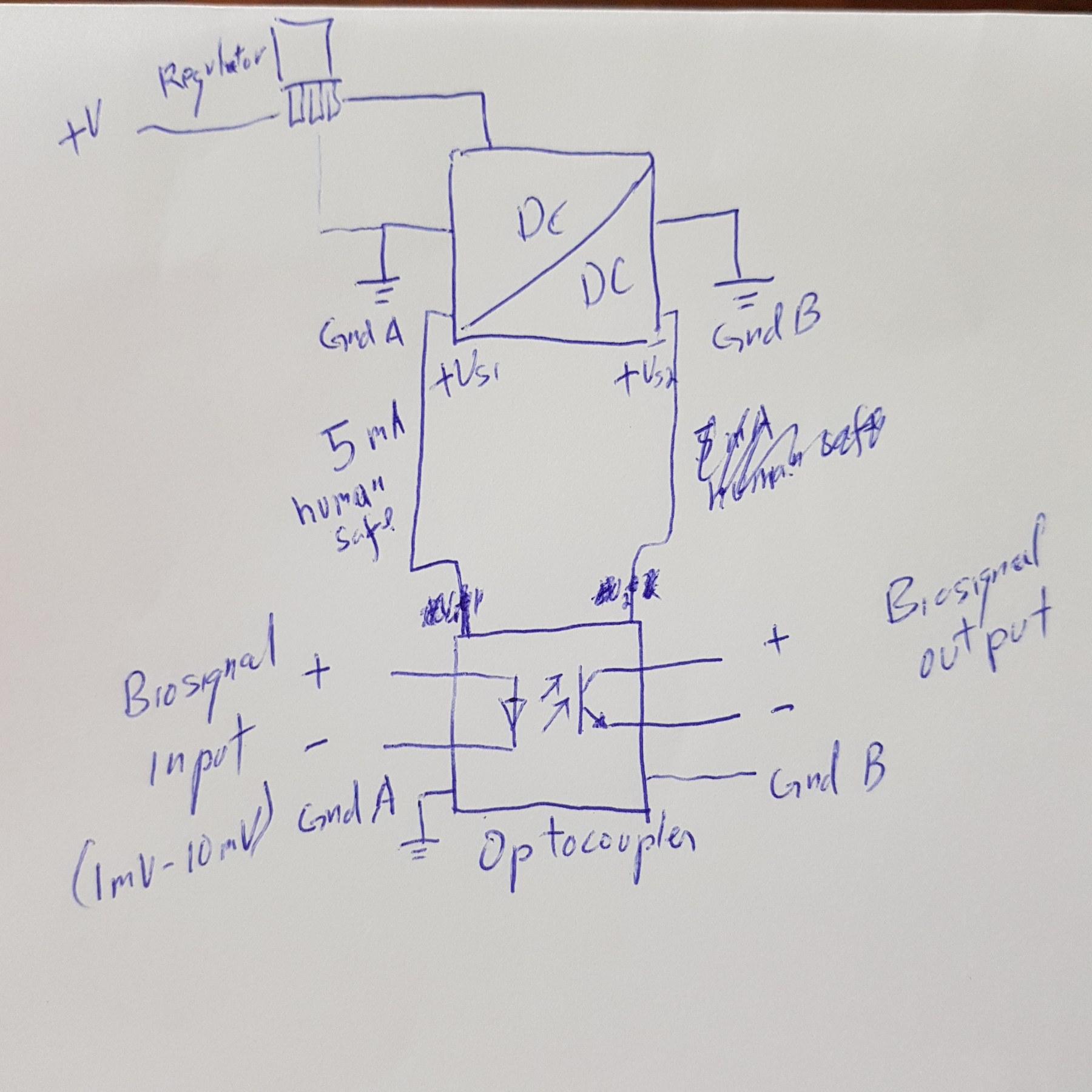
The application is biopotential signal of 1mV to 10mV differential + and - with common (or ground), one channel only. The optocoupler will move the biosignal across the isolation barrier, and the DC-DC converter is needed to provide power for the isolated side while maintaining the isolation. The DC current of the input circuit of the optocoupler must be 5mA or human safe so in the event the optocoupler has fault and the isolation is broken, huge DC current from device (battery operated) wouldn't get into the skin (which is abraded so resistance is not very high).

The biosignal output must be similar to the input with no gain , no distortion and noises introduced. What optocoupler, DC-DC converter can be used for this purpose?  Frequency range can be 2500Hz, doesn't have to be 20000Hz. What is the frequency response of a typical optocoupler?

Since the application can be used in any input in any generic device. Isn't there any finished product like it?
« Last Edit: February 08, 2024, 03:31:06 am by loop123 »
 

Offline Andy Chee

  • Frequent Contributor
  • **
  • Posts: 688
  • Country: au
Re: Optocoupler with DC-DC converter and regulator in a board with chassis
« Reply #4 on: February 08, 2024, 03:35:15 am »
The biosignal output must be similar to the input with no gain , no distortion and noises introduced. What optocoupler, DC-DC converter can be used for this purpose?  Frequency range can be 2500Hz, doesn't have to be 20000Hz. What is the frequency response of a typical optocoupler?
Frequency response is not a problem for optocouplers.  The big problem for optocouplers is distortion, they are normally used for digital signals, not analogue signals (power supply feedback circuits excepted).

Since the application can be used in any input in any generic device. Isn't there any finished product like it?
https://www.adinstruments.com/products/bio-amps

https://physicsopenlab.org/2020/02/04/biopotential-amplifier/ (no isolation though, you will have to add your own IL300 and iso-power supply)
« Last Edit: February 08, 2024, 03:38:25 am by Andy Chee »
 

Online moffy

  • Super Contributor
  • ***
  • Posts: 1749
  • Country: au
Re: Optocoupler with DC-DC converter and regulator in a board with chassis
« Reply #5 on: February 08, 2024, 04:18:43 am »
What you need is a medical grade isolation amplifier and DC/DC supply unless of course you use batteries on the sensor side and only charge them when not attached to a person. They have a whole different level of qualification and standards to normal electronics and need to be rated for medical use. The only example after a brief search is: https://www.digitimer.com/product/life-science-research/amplifiers/nl820a-isolation-amplifier/
which I cannot vouch for, having never had the need to use.
 

Offline loop123Topic starter

  • Frequent Contributor
  • **
  • !
  • Posts: 297
  • Country: ca
Re: Optocoupler with DC-DC converter and regulator in a board with chassis
« Reply #6 on: February 08, 2024, 05:19:59 am »

I already have a bioamplifier powered by 12 pcs of 1.2V rechargeable NiMh batteries for total of 14.4V DC. However, if I will just use an optocoupler and there is fault inside the optocoupler photon gap, it can conduct 14.V dc either from the optocoupler emitter or detector circuit side to the user input. Imagine what would happen to you if you got exposed to 14.4V DC and your chest area is abraded, and your resistance is low. Then the 14.4V DC huge current can get into the skin and stop your heart.

Btw.. what is the maximum current that can be produced by 12pcs of 2500mAH 1.2v Ni-Mh for total of 14.4V if the resistance of the load or your skin is minimal?

Therefore the DC-DC is important because it would limit the user input circuit to only 5mA. And in the even of optocoupler fault. At least you are exposed only to 5mA.

With the above. Please give recommendation for the best optocoupler. Andy said it has distortions for analog signals? Why is that? how bad is it?  After we select the best optocoupler, then we can easily choose the DC-DC converter.

Thanks.
 

Online moffy

  • Super Contributor
  • ***
  • Posts: 1749
  • Country: au
Re: Optocoupler with DC-DC converter and regulator in a board with chassis
« Reply #7 on: February 08, 2024, 05:24:54 am »
You can quite easily limit the output of the batteries to 5ma or much better since there are so many good low voltage opamps etc available just work from say a 3V supply, you are only dealing with 1-10mv signals and you can still limit the 3V supply to 5ma.
 

Offline Andy Chee

  • Frequent Contributor
  • **
  • Posts: 688
  • Country: au
Re: Optocoupler with DC-DC converter and regulator in a board with chassis
« Reply #8 on: February 08, 2024, 06:27:33 am »
Please give recommendation for the best optocoupler.
For analog signals, you can either use an analog optocoupler like the IL300 or HCNR200, or you can first convert the analog signal to digital and transmit the digital signal across any digital optocoupler.

In both scenarios, you will need another opamp in front of the isolation barrier, because neither analog nor digital optoisolator will be able to respond to 1mV signals.
« Last Edit: February 08, 2024, 06:30:41 am by Andy Chee »
 

Offline loop123Topic starter

  • Frequent Contributor
  • **
  • !
  • Posts: 297
  • Country: ca
Re: Optocoupler with DC-DC converter and regulator in a board with chassis
« Reply #9 on: February 08, 2024, 08:54:12 am »
You can quite easily limit the output of the batteries to 5ma or much better since there are so many good low voltage opamps etc available just work from say a 3V supply, you are only dealing with 1-10mv signals and you can still limit the 3V supply to 5ma.

What circuit can you use (or finished product) to limit the 14.4V (12 pcs of 2500maH 1.2v NiMH rechargeable batteries) to 5ma?  I'll try to adjust the current limit lower and lower to see what current lowest the amplifier can run. Won't doing this damage the amplifier? Thanks.
 

Online moffy

  • Super Contributor
  • ***
  • Posts: 1749
  • Country: au
Re: Optocoupler with DC-DC converter and regulator in a board with chassis
« Reply #10 on: February 08, 2024, 10:26:07 pm »
Remove ZD1 from the first circuit and you have a current limiter circuit, the current is set roughly by the voltage drop across D2 divided by R2 or Io = Vd2/R2 and Vd2 is about 0.7V. It's not very accurate. There are better configurations if you want to search for them.

P.S. https://www.electronics-notes.com/articles/analogue_circuits/power-supply-electronics/current-limiter-circuit.php
« Last Edit: February 08, 2024, 11:09:01 pm by moffy »
 

Offline loop123Topic starter

  • Frequent Contributor
  • **
  • !
  • Posts: 297
  • Country: ca
Re: Optocoupler with DC-DC converter and regulator in a board with chassis
« Reply #11 on: February 08, 2024, 10:55:00 pm »
Remove ZD1 from the first circuit and you have a current limiter circuit, the current is set roughly by the voltage drop across D2 divided by R2 or Io = Vd2/R2 and Vd2 is about 0.7V. It's not very accurate. There are better configurations if you want to search for them.

What ZD1? what D2, R2? What are you talking about? Maybe you were responding to another person message? My battery is only this configuration:

2008424-0

Where to put resistor to limit the current to say 5mA only?
 

Online moffy

  • Super Contributor
  • ***
  • Posts: 1749
  • Country: au
Re: Optocoupler with DC-DC converter and regulator in a board with chassis
« Reply #12 on: February 08, 2024, 11:10:00 pm »
Sorry, my bad the link was left out. :palm:
It is in the original post now.
 

Offline loop123Topic starter

  • Frequent Contributor
  • **
  • !
  • Posts: 297
  • Country: ca
Re: Optocoupler with DC-DC converter and regulator in a board with chassis
« Reply #13 on: February 08, 2024, 11:26:05 pm »
Sorry, my bad the link was left out. :palm:
It is in the original post now.

It's complicated to use and build that circuit in a pcb. Why can't I just put a resistor in series with the supply illustrated? For example, since the voltage is 7.95V, and required current is 5mA. Why not R=V/I = 7.95/0.005 = 1590 Ohms?

If that wont it (and why not)? Why can't I just use an isolated DC-DC converter with 5mA output? Isn't there such?
« Last Edit: February 08, 2024, 11:28:25 pm by loop123 »
 

Offline loop123Topic starter

  • Frequent Contributor
  • **
  • !
  • Posts: 297
  • Country: ca
Re: Optocoupler with DC-DC converter and regulator in a board with chassis
« Reply #14 on: February 09, 2024, 12:29:45 am »
To illustrate above. I was looking for an isolated DC-DC converter with 10mA or less output but even this brand that caters medical can reach 200mA! We know 90mA is also hazardous for the heart. Is it because isolated DC-DC converter purpose is to isolate from ground and not to protect from the DC itself?? see specs:

2008517-0

2008523-1

2008529-2
 

Online moffy

  • Super Contributor
  • ***
  • Posts: 1749
  • Country: au
Re: Optocoupler with DC-DC converter and regulator in a board with chassis
« Reply #15 on: February 09, 2024, 12:31:02 am »
Sorry, my bad the link was left out. :palm:
It is in the original post now.

It's complicated to use and build that circuit in a pcb. Why can't I just put a resistor in series with the supply illustrated? For example, since the voltage is 7.95V, and required current is 5mA. Why not R=V/I = 7.95/0.005 = 1590 Ohms?

If that wont it (and why not)? Why can't I just use an isolated DC-DC converter with 5mA output? Isn't there such?
If you don't mind the voltage drop with current, remember each 1mA will drop you voltage by 1.59V.
 

Offline loop123Topic starter

  • Frequent Contributor
  • **
  • !
  • Posts: 297
  • Country: ca
Re: Optocoupler with DC-DC converter and regulator in a board with chassis
« Reply #16 on: February 09, 2024, 01:32:52 am »
Sorry, my bad the link was left out. :palm:
It is in the original post now.

It's complicated to use and build that circuit in a pcb. Why can't I just put a resistor in series with the supply illustrated? For example, since the voltage is 7.95V, and required current is 5mA. Why not R=V/I = 7.95/0.005 = 1590 Ohms?

If that wont it (and why not)? Why can't I just use an isolated DC-DC converter with 5mA output? Isn't there such?
If you don't mind the voltage drop with current, remember each 1mA will drop you voltage by 1.59V.

How did you compute 1mA and voltage drop of 1.59V from my computations? and what you mean "each 1mA will drop you voltage by 1.59V". Each 1mA used inside circuit??  If the circuit used 3mA, it will drop voltage by 1.59x3= 4.77V (inside the circuit or the resistor outside)?  Also where will I put the resistor?  The circuit needs V+ and V- so my battery is designed this way to have a common ground so it can create +V and -V. Will I put the resistor in each +V and -V, what value?


2008547-0

Also don't miss the message about the isolated DC-DC just before your message which we sent at same time. Thanks.
« Last Edit: February 09, 2024, 01:47:30 am by loop123 »


Share me

Digg  Facebook  SlashDot  Delicious  Technorati  Twitter  Google  Yahoo
Smf