Author Topic: Optoelectronics - die pictures  (Read 18338 times)

0 Members and 1 Guest are viewing this topic.

Offline NoopyTopic starter

  • Super Contributor
  • ***
  • Posts: 1729
  • Country: de
    • Richis-Lab
Optoelectronics - die pictures
« on: September 18, 2020, 09:38:12 pm »
Hi all!


I need a topic for optoelectronic pictures.  8)

You can find the main page here:
https://richis-lab.de/Opto.htm


Today I have uploaded pictures of the 7 segment led display VQB17 built in the "Werk für Fernsehelektronik Berlin":


In a red cap there is a opaque foil above a white light shaper with a black textured surface.


You can see the LEDs through the light shaper.
...In the middle there is a loose bondwire...


To connect the pins to the board they used pressfit technology. Very cool!  :-+


The die is 310µm x310µm.
You can spot a MESA structure and a dark square. I assume the dark square is some highly doped contact area.


You can´t really recognize which part of the structure is glowing because the light spreads through the semiconductor and the protective coat all over the die surface.
It start´s glowing at 5µA.


The LED glows also at -12V (2,5mA)...  ;D
The light is much less uniform and of course a lot darker.


More pictures here:

https://richis-lab.de/Opto02.htm

 :-/O
« Last Edit: September 19, 2020, 06:59:44 am by Noopy »
 

Offline NoopyTopic starter

  • Super Contributor
  • ***
  • Posts: 1729
  • Country: de
    • Richis-Lab
Re: Optoelectronics - die pictures
« Reply #1 on: September 24, 2020, 08:27:42 pm »
Let´s look inside a blinking LED:

https://richis-lab.de/Opto03.htm


You can´t burn the package stuff like epoxy mould. There is always some sticky dirt left. But you can take pictures through the package. The quality is a bit worse but it´s ok...


The "controller" is 0,48mm x 0,46mm the LED is 0,2mm x 0,19mm.


As expected there is a RC oscillator which frequency is divided with the help of 19 flip-flops.
And hey, the die has two outputs. It can be used to drive two LEDs alternating.
Since the outputs a current sources the not used output is connected to ground.


The current flowing into the LED shows that the second stage consumes nearly the same current as the first stage.
The blinking frequency is round about 1,2Hz.


You can see the oscillator frequency between the pins. The frequency is 0,59MHz. Devided by 19 you get 1,1Hz. That´s quite close to the 1,2Hz observed in the current flow. The frequency is not very stable.

 :-/O

Offline Zero999

  • Super Contributor
  • ***
  • Posts: 19491
  • Country: gb
  • 0999
Re: Optoelectronics - die pictures
« Reply #2 on: September 24, 2020, 10:01:18 pm »
Thanks a lot.

What does Pre mean?

Presumably you don't need a series resistor for that particular LED? I always thought flashing LEDs still needed one.

Another thing which interests me is the maximum operating voltage is seldom mentioned on flashing LED datasheets. In another thread someone ran one off rectified 24VAC, so nearly 34V, via a suitable resistor, with no problems.
 

Offline Renate

  • Super Contributor
  • ***
  • Posts: 1460
  • Country: us
Re: Optoelectronics - die pictures
« Reply #3 on: September 24, 2020, 11:05:53 pm »
Looks nice.

Hey, what's your camera/optics/filters/polarization/lighting?
(I can't find any info on your website, auf Englisch oder Deutsch.)
 

Offline David Hess

  • Super Contributor
  • ***
  • Posts: 16607
  • Country: us
  • DavidH
Re: Optoelectronics - die pictures
« Reply #4 on: September 24, 2020, 11:11:35 pm »
I thought the old style blinking LEDs were fabricated as one chip.
 

Offline profdc9

  • Frequent Contributor
  • **
  • Posts: 319
  • Country: us
Re: Optoelectronics - die pictures
« Reply #5 on: September 25, 2020, 02:30:33 am »
If you immerse the plastic in an indexing matching liquid such as glycerin (index of refraction 1.47) or corn syrup (index of refraction 1.53), you can make the bulb "disappear."  Then place a flat piece of glass like a watch glass or a microscope slide on top of the liquid and you should get a very good picture.

 
The following users thanked this post: BravoV, Noopy

Offline NoopyTopic starter

  • Super Contributor
  • ***
  • Posts: 1729
  • Country: de
    • Richis-Lab
Re: Optoelectronics - die pictures
« Reply #6 on: September 25, 2020, 03:15:49 am »
What does Pre mean?

Pre stands for Predriver.


Presumably you don't need a series resistor for that particular LED? I always thought flashing LEDs still needed one.

Another thing which interests me is the maximum operating voltage is seldom mentioned on flashing LED datasheets. In another thread someone ran one off rectified 24VAC, so nearly 34V, via a suitable resistor, with no problems.

I wasn´t sure first. This blinking LED also had no datasheet. On the package it says 5V and 20mA and with 5V it works consuming round about 20mA.  :-+ ;D But of course it´s possible that there are a lot of blinking LEDs needing a resistor. I have to admit that was the first blinking LED I had on my table.


Looks nice.

Hey, what's your camera/optics/filters/polarization/lighting?
(I can't find any info on your website, auf Englisch oder Deutsch.)

Thanks!  :)
I have a HowTo-page: https://www.richis-lab.de/Howto.htm
I have to update the pages but basically I still work with this equipment.
Here you can find some discussion regarding the HowTo: https://www.eevblog.com/forum/projects/decapping-and-chip-documentation-howto/msg2663778/#msg2663778


I thought the old style blinking LEDs were fabricated as one chip.

Perhaps I have to take some more pictures...  :)


If you immerse the plastic in an indexing matching liquid such as glycerin (index of refraction 1.47) or corn syrup (index of refraction 1.53), you can make the bulb "disappear."  Then place a flat piece of glass like a watch glass or a microscope slide on top of the liquid and you should get a very good picture.

Thans for the hint!  :-+
 
The following users thanked this post: Zero999, Renate

Offline NoopyTopic starter

  • Super Contributor
  • ***
  • Posts: 1729
  • Country: de
    • Richis-Lab
Re: Optoelectronics - die pictures
« Reply #7 on: October 08, 2020, 09:17:59 pm »

Let´s look into a infrared camera module: Flir Lepton 2.5


The Lepton 2.5 uses a shutter to calibrate the temperature measured with the microbolometer pixel.


A temperature sensor on top of the module measures the temperature of the shutter (near the shutter  ;)).
Yes, the module suffered some water damage.  ;D


On top of the sensor there are two lenses in a "screw". By screwing this optic in and out you can adjust the focus.
The lenses are probably built out of silicon.


The housing uses a conductive coating. Here you can see the second lens in the "screw".


The sensor module is quite big. Under the die in the middle there is a 0,6mm copper heatspreader. The heatspreader has to guarantee a uniform temperature over the die.
On top of the middle die there is an other die that forms a vacuum chamber. Gases would cool the sensor pixels.


The top level die has a coating to reduce infrared reflection.
The lenses had also a coating.


The top level die has a coating on the bottom to damp light outside the active area.


Some damage...  :'(


Here you can see the sensor array with the first signal processing.
Under the big metal rectangles there are probably the dark reference pixels.
In the upper left corner you can see a small 4x3 array probably also some reference.


One pixel is 17x17µm as Flir states in the datasheet. The diameter of one active area is round about 15µm.


Well it´s kind of a MEMS. You can see the height of the pixels. The distance is important to thermaly isolate the pixel from the substrate.


Even careful cleaning damages the pixel structures.
But here you can see the structures of the last two pixels seem to be corrupted. For a resolution of 80x60 the die uses 84x64 pixels. As seen with the DLP (https://richis-lab.de/DLP.htm) these MEMS-structures need dummy parts at the edge.


Can´t say much about the signal processing flip-chip. Damn underfiller.  >:(


I assume the small one is a voltage regulator.


More pictures here:

https://richis-lab.de/Opto04.htm

 :-/O

Offline capt bullshot

  • Super Contributor
  • ***
  • Posts: 3033
  • Country: de
    • Mostly useless stuff, but nice to have: wunderkis.de
Re: Optoelectronics - die pictures
« Reply #8 on: October 09, 2020, 05:15:16 pm »
Thanks, these are very fascinating pictures.
Safety devices hinder evolution
 

Offline tooki

  • Super Contributor
  • ***
  • Posts: 11473
  • Country: ch
Re: Optoelectronics - die pictures
« Reply #9 on: October 09, 2020, 06:09:51 pm »
Great pictures as always!


In a red cap there is a opaque foil above a white light shaper with a black textured surface.
Well, clearly it’s not opaque — “opaque” means “lichtundurchlässig”. (Same as “opak” in German.) It’d be accurate to call it a translucent film. (“Foil” in English refers exclusively to thin metal, not other materials. Those we call “films”.)
 

Offline RoGeorge

  • Super Contributor
  • ***
  • Posts: 6185
  • Country: ro
Re: Optoelectronics - die pictures
« Reply #10 on: October 09, 2020, 06:25:39 pm »
Wow, that IR sensors!   :o
Very nice pics, thank you.

It looks like there is a small lens above each pixel, and some of the pixels lost their lens.  How are those lens made?  Are they grown on top of the circuit, or fabricated separately then glued on top later?   :-//

Offline NoopyTopic starter

  • Super Contributor
  • ***
  • Posts: 1729
  • Country: de
    • Richis-Lab
Re: Optoelectronics - die pictures
« Reply #11 on: October 09, 2020, 06:34:05 pm »
Thank you all!  :)

tooki you are right. I was wrong. "opaque" and "opak" are both wrong.
Also the hint regarding "foil" is interesting. Kind of a false friend.
Thank you! :-+


It looks like there is a small lens above each pixel, and some of the pixels lost their lens.  How are those lens made?  Are they grown on top of the circuit, or fabricated separately then glued on top later?   :-//

That small parts are small plates which are mounted elevated over the substrate so they don´t loose thermal energy. You want to isolate these plates as good as possible to convert every infrared photon into a delta T.
At first most of the pixels looked good but while cleaning the die I damaged a lot of them.
The structures are fabricated like every MEMS. You stack special layers and etch one of the lower layers away.
I have written some words about that here: https://www.eevblog.com/forum/projects/dlp-die-pictures/msg2967068/#msg2967068
 
The following users thanked this post: brabus, RoGeorge

Offline tooki

  • Super Contributor
  • ***
  • Posts: 11473
  • Country: ch
Re: Optoelectronics - die pictures
« Reply #12 on: October 09, 2020, 07:45:56 pm »
Thank you all!  :)

tooki you are right. I was wrong. "opaque" and "opak" are both wrong.
Also the hint regarding "foil" is interesting. Kind of a false friend.
Thank you! :-+
Indeed! There are lots of false friends, from the classic “actual” vs. “aktuell”, “when” vs “wenn”, “eventually” vs. “eventuell”, to really subtle ones like the difference between the English word “manager” and the German word “Manager”* (which was obviously borrowed from English, but actually means something subtly different, but similar enough that people who aren’t truly bilingual won’t realize the other person means something else), and amusing ones like “body bag”, which means radically different things** in the two languages! 😂

*English “manager” means a person at any level of management, even way down at the bottom with just one layer of subordinates. In German, “Manager” specifically and exclusively refers to executive-level management. (English “manager” is “Leiter” in German, e.g. store manager is “Filialleiter”.)

**In German, a “body bag” is a one-strap backpack. In English, it’s the bag you use to hold a cadaver.
 
The following users thanked this post: james_s, schmitt trigger

Offline edavid

  • Super Contributor
  • ***
  • Posts: 3381
  • Country: us
Re: Optoelectronics - die pictures
« Reply #13 on: October 09, 2020, 08:29:58 pm »
(“Foil” in English refers exclusively to thin metal, not other materials. Those we call “films”.)

Except that an overhead projector transparency is often called a "viewfoil"  :-//
 

Online T3sl4co1l

  • Super Contributor
  • ***
  • Posts: 21657
  • Country: us
  • Expert, Analog Electronics, PCB Layout, EMC
    • Seven Transistor Labs
Re: Optoelectronics - die pictures
« Reply #14 on: October 09, 2020, 09:38:50 pm »
And every so often you see plastics referred to as foils, seems to sometimes show up with polyimide (particularly strong? shiny? golden?), maybe thicker pieces of mylar etc.  Not sure why.

Tim
Seven Transistor Labs, LLC
Electronic design, from concept to prototype.
Bringing a project to life?  Send me a message!
 

Offline tooki

  • Super Contributor
  • ***
  • Posts: 11473
  • Country: ch
Re: Optoelectronics - die pictures
« Reply #15 on: October 12, 2020, 01:33:16 pm »
(“Foil” in English refers exclusively to thin metal, not other materials. Those we call “films”.)

Except that an overhead projector transparency is often called a "viewfoil"  :-//
I never, ever heard them called that when I was in school.
 

Offline tooki

  • Super Contributor
  • ***
  • Posts: 11473
  • Country: ch
Re: Optoelectronics - die pictures
« Reply #16 on: October 12, 2020, 01:34:44 pm »
And every so often you see plastics referred to as foils, seems to sometimes show up with polyimide (particularly strong? shiny? golden?), maybe thicker pieces of mylar etc.  Not sure why.

Tim
Maybe association with the metalized versions of those plastic films.
 

Offline NoopyTopic starter

  • Super Contributor
  • ***
  • Posts: 1729
  • Country: de
    • Richis-Lab
Re: Optoelectronics - die pictures
« Reply #17 on: February 20, 2021, 09:46:01 pm »
More light!  8)


VQC10, a Dot-Matrix-Display with four 7x5 segments built by the Werk für Fernsehelektronik Berlin. Usually the VQC10 is potted but this one is a development part.
Interesting point: The VQC10 usually has a continuous pin row at the lower edge, here we see a big gap in the middle. The datasheet states the missing pins are used to transfer the heat out of the module. It seems like they got problems with the temperature while developing the VQC10...


There is a application note showing that the huge number of LEDs (140) drives the heat transfer to its limits. With a ambient temperature of 85°C you have to reduce the supply voltage to 2,5V or the pulse width to 1:25.


On the lower part of the board there are four 6-Flip-Flop-Dies controlling the columns.


It´s a development part. There is no connection to the FlipFlops but they connected the first three columns of all segments together and they connected the last two columns of all segments together.
The boreholes between the lines are interesting. I assume there have been connections so it was easier to test all LEDs in production. After testing you drill the holes and the VQC10 acts as it is designed to act.


The FlipFlop-Die has seen better days. It´s cracked in the upper right corner...


You can clearly see the output transistor with four resistors for adjusting the LED current.


A lot of the LED dies are not connected to the bondwire. Back in the days they had quite some problems with the bond quality.


The LEDs are 0,46mm x 0,46mm.
The datasheet states that GaAsP was used to built the LED.
In the VQB17 (https://www.richis-lab.de/Opto02.htm) they used AlGaAs which is more efficient than GaAsP. I assume they didn´t use AlGaAs in the VQC10 because back in the days these LEDs were less robust. Perhaps that would have been a problem with the high temperatures in the VQC10.


With the right display you can see a small glimpse at 5µA.


For all others here you see 10µA.


2mA


Now that is interesting!  8)
GaAsP-LEDs are fabricated on a GaAs substrate. The lower dark area is the GaAs. The bright layer is the GaAsP. GaAs has a smaller bandgap than GaAsP and therefore can absorb the light generated in the upper layer quite efficient. Because of that the lower part is dark.


Breakdown occurs first at 22V!  :o
Here you see 900µA. The light emission occurs only at the borders of the p-doped region. I assume that is because of the higher electrical field and the higher impurity density.


More pictures here:

https://www.richis-lab.de/Opto05.htm

 :-/O
 
The following users thanked this post: RoGeorge, Miyuki, capt bullshot

Offline Renate

  • Super Contributor
  • ***
  • Posts: 1460
  • Country: us
Re: Optoelectronics - die pictures
« Reply #18 on: February 21, 2021, 04:12:04 pm »
A lot of the LED dies are not connected to the bondwire. Back in the days they had quite some problems with the bond quality.
I think that they just got bored bonding on this development device.
 

Offline NoopyTopic starter

  • Super Contributor
  • ***
  • Posts: 1729
  • Country: de
    • Richis-Lab
Re: Optoelectronics - die pictures
« Reply #19 on: February 21, 2021, 04:33:39 pm »
A lot of the LED dies are not connected to the bondwire. Back in the days they had quite some problems with the bond quality.
I think that they just got bored bonding on this development device.

You are right. In this device they stopped bonding but they had quite some problems with the quality of the bonds.  :-+

Offline NoopyTopic starter

  • Super Contributor
  • ***
  • Posts: 1729
  • Country: de
    • Richis-Lab
Re: Optoelectronics - die pictures
« Reply #20 on: March 28, 2021, 08:40:24 pm »


Worldsemi WS2812B, an intelligent RGB-LED.
The potting is clear enough to take pictures through it.


The WS2812B has four contacts: Vdd, Vss, Data_In and Data-Out.
Interesting: The red LED is connected to Vdd by its substrate while the green and the blue LED needed a second bondwire to contact Vdd.


The red LED has an edge length of 0,17mm.


The edge length of the green and the blue LED is 0,20mm.
The structures look similar to a small signal transistor. There is a very small patterning on the surface.


The control die is 0,9mm x 0,7mm.
You can see the lines of the gatearray logic in the lower part of the die. The upper left area probably contains the housekeeping.


In the lower left corner there are the three "power stages".
I assume the structures on the left are some protection whatever. I don´t think they have put the power stages at the edge of the die.
The greenish squares are connected quite massive with the bondpads and Vss. It would be logical that these are the current sink transistors.
The following smaller structures... ...perhaps the current regulation circuits?

There is a fourth bonpad. A RGBW-controller? No, I don´t think so. The fourth structure looks different. The connection to the bondpad is smaller, the square looks different and the supposed current regulator is mirrored. In my opinion with this structure you can adjust the LED current.


There seems to be a fusible link in the upper left corner of the bondpad. That seems plausible. With the fuse connected you have the normal current, with the fuse cut you can adjust the current with an external resistor. Probably...  :-/O


https://www.richis-lab.de/Opto06.htm

 :-/O
 
The following users thanked this post: doktor pyta, RoGeorge

Offline NoopyTopic starter

  • Super Contributor
  • ***
  • Posts: 1729
  • Country: de
    • Richis-Lab
Re: Optoelectronics - die pictures
« Reply #21 on: April 30, 2021, 04:32:11 am »


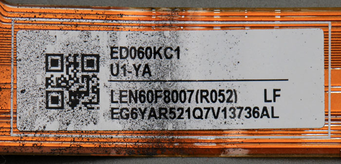
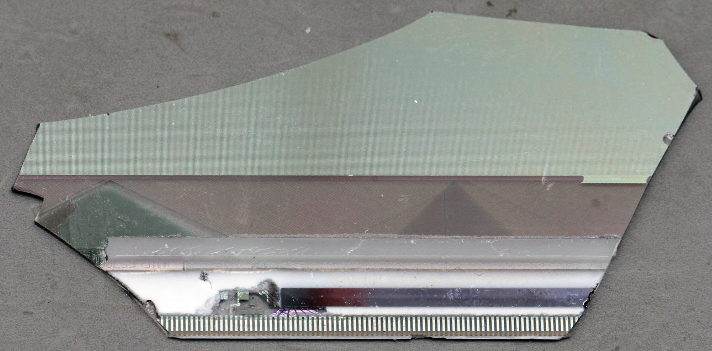
The ED060KC1 is a e-paper display used in the Kindle Paperwhite 3. It supplies you with a 16 greyscale 1072 x 1448 resolution.
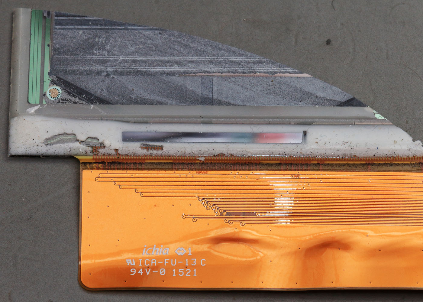
I own a fragment of the display. The top glass is already removed. We see the lower glass with the TFT electronics and the active mass.


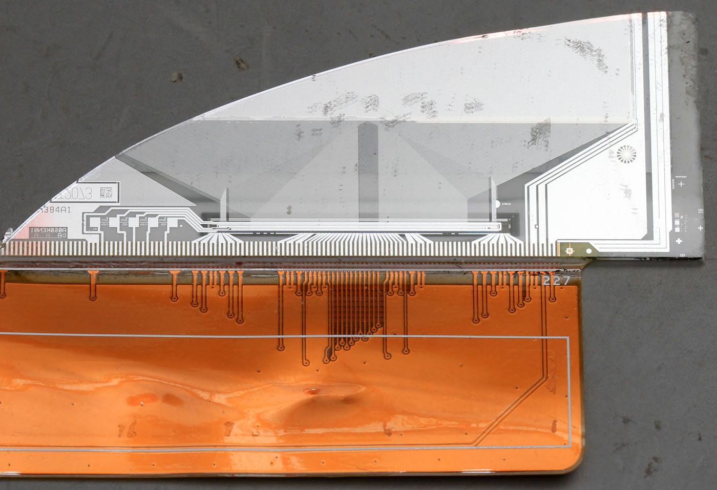
If we turn the glass we see the undermost metalisation of the upper side.


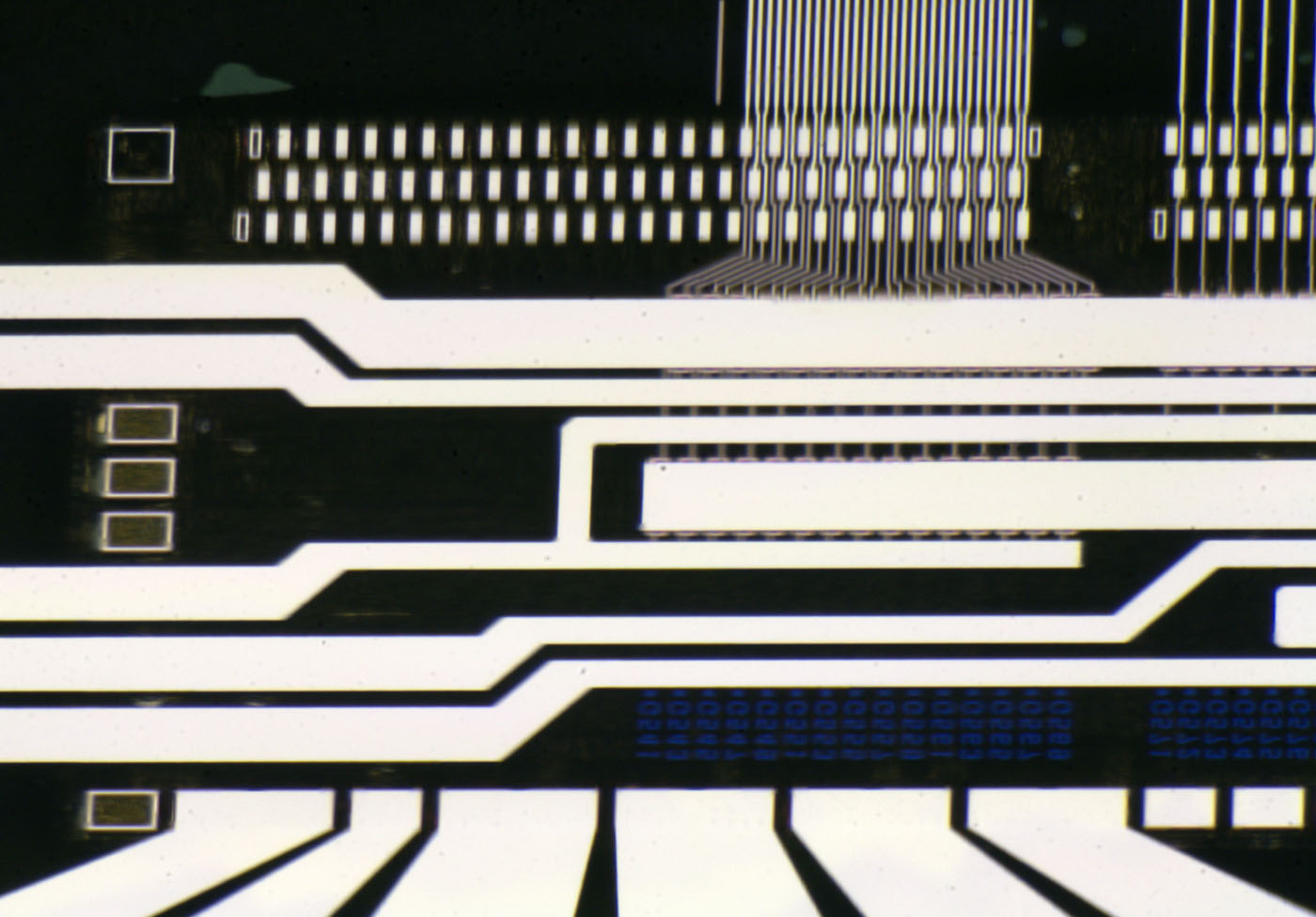
Here is the controller. Some tracks come from the flex connector and a huge amount of signals travel to the display.


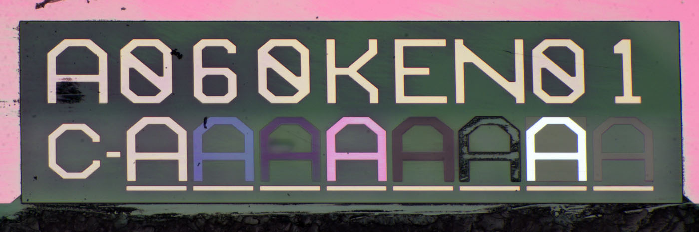
Probably A060KEN01 is the panel name.
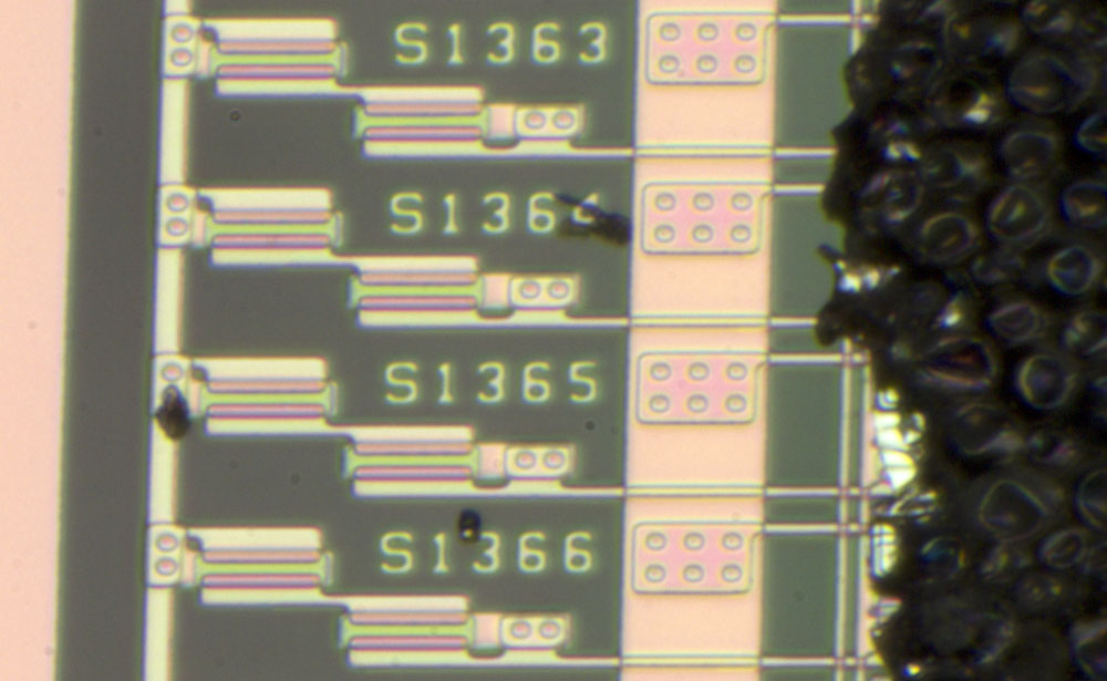
We see eight mask revisions.


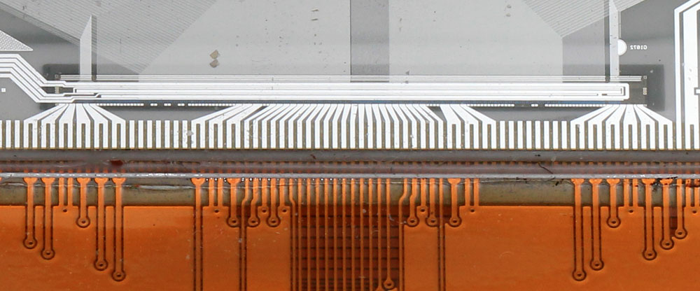
Is everything aligned properly?


Probably that´s the contact connecting the upper glass that is just the upper electrode for the whole display.


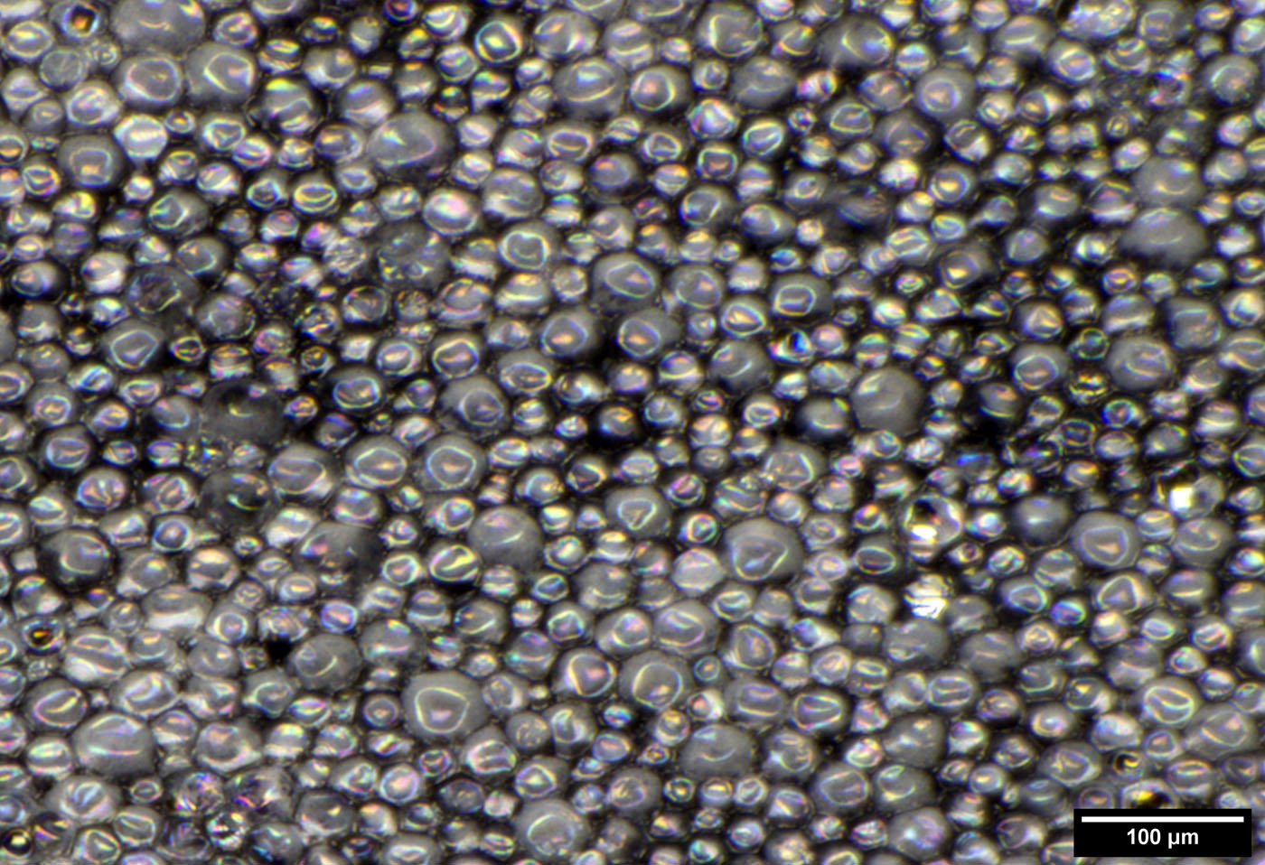
The active mass consists of bubbles with a diameter of up to 60µm containing pigments that travel through the bubble depending on the electrical field. Then the bubble is dark or bright.


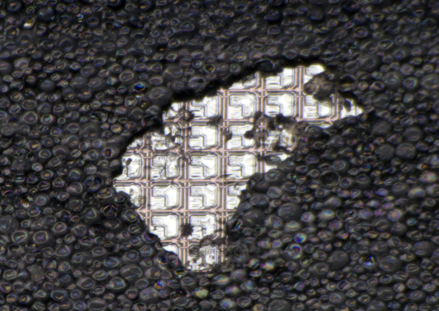
Under the thin layer of this active mass we have the TFT circuit.


Datasheet says the dot pitch is 84µm.
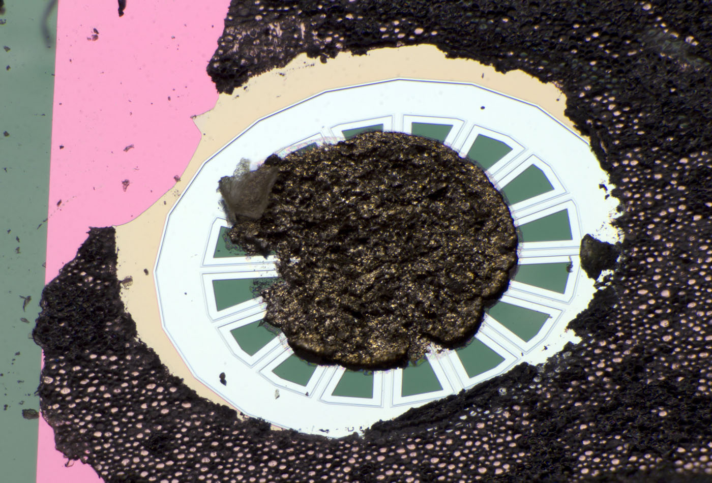
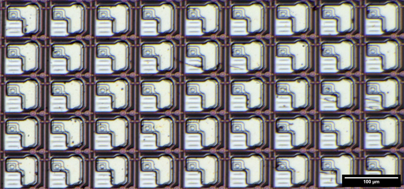
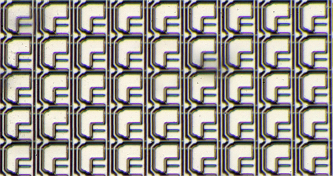
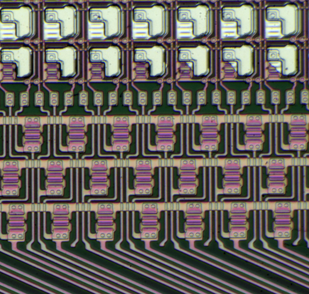
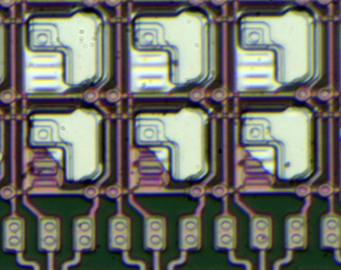
The bright area is the upper electrode controlling the electrical field around the active mass.
On the upper electrode we see the contours of a capacitor (the bigger area) and the pixel switch (the smaller square).
You need a capacitor because the pigments in the bubbles are quite slow but you want to switch the pixel fast.

Around the pixel there are supply and control lines. There are two horizontal lines. One line is the reference for the capacitor in the pixel, one is the activation line for the whole row.
There are three vertical lines. One line is controlling the gates of the transistors of the pixel column. The other two lines seem to be connected to every horizontal line. That can´t be true because then it would be impossible to address one single line. It seems like the controller is selecting the pixel rows by these additional vertical lines. In pictures of the complete display you can´t spot a controller on the sides of the panel.


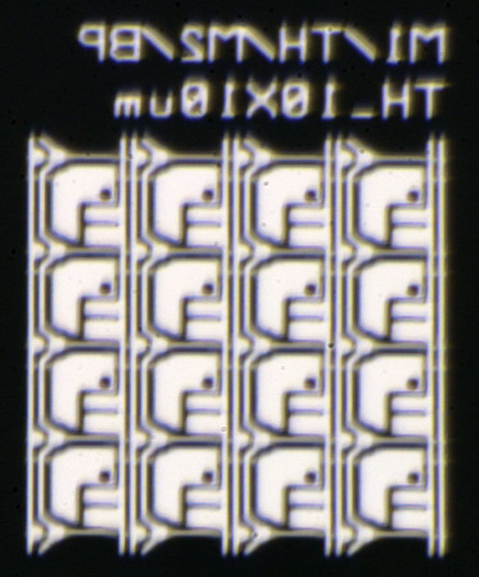
From the bottom of the glass we can take a look at the undermost metal layer. We clearly see the two gate electrodes of every pixel. You need two electrodes because TFT transistors have a high leakage current. With the high voltage (something around +/-10-20V) the current flow would degrade the pixel status.


On the left side of the panel the capacitor reference is connected directly to one big metal line. The row selection line is connected to two transistors probably acting as a pull-up or pull-down.


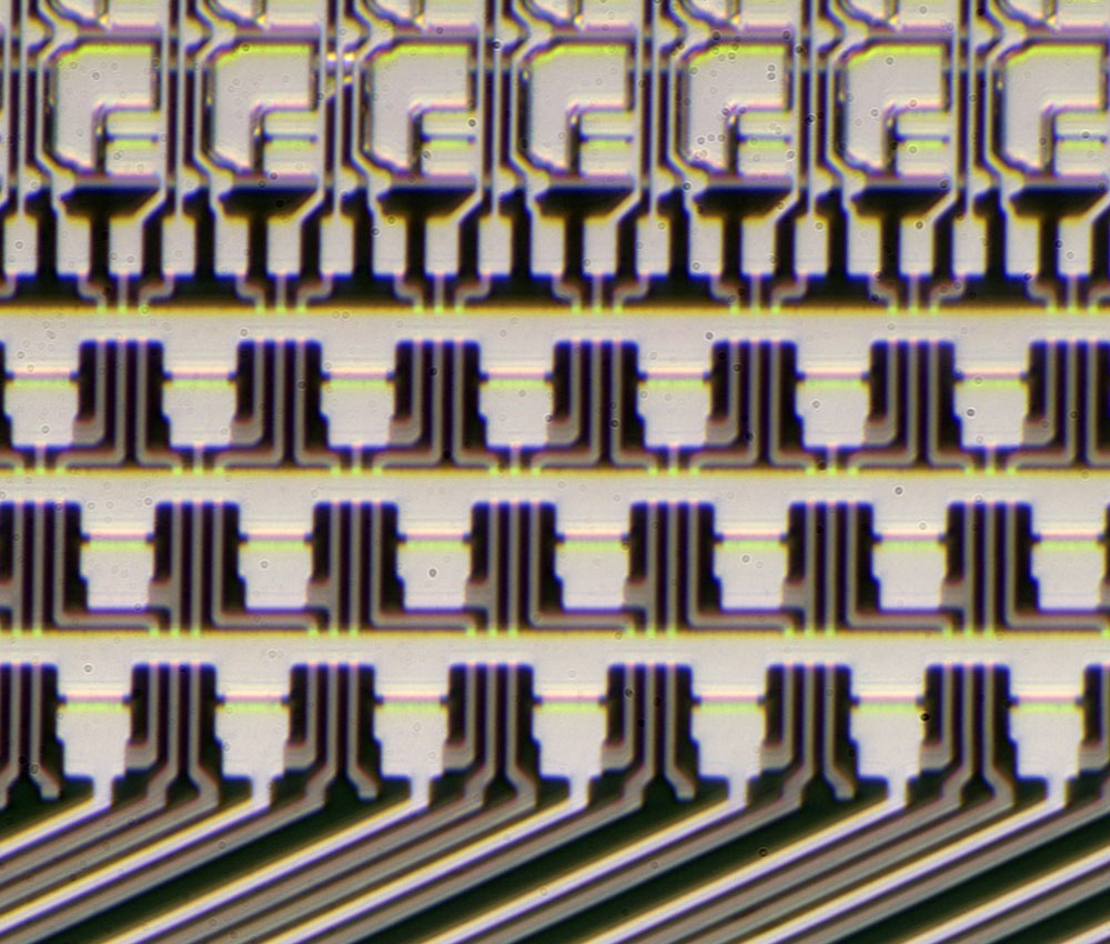
On the lower part of the panel there are three big lines acting as pull-up or pull-down for the control lines.
Not every line is connected. That is plausible because for 1072 x 1448 dots you need 1,35 row control lines for every column control line.


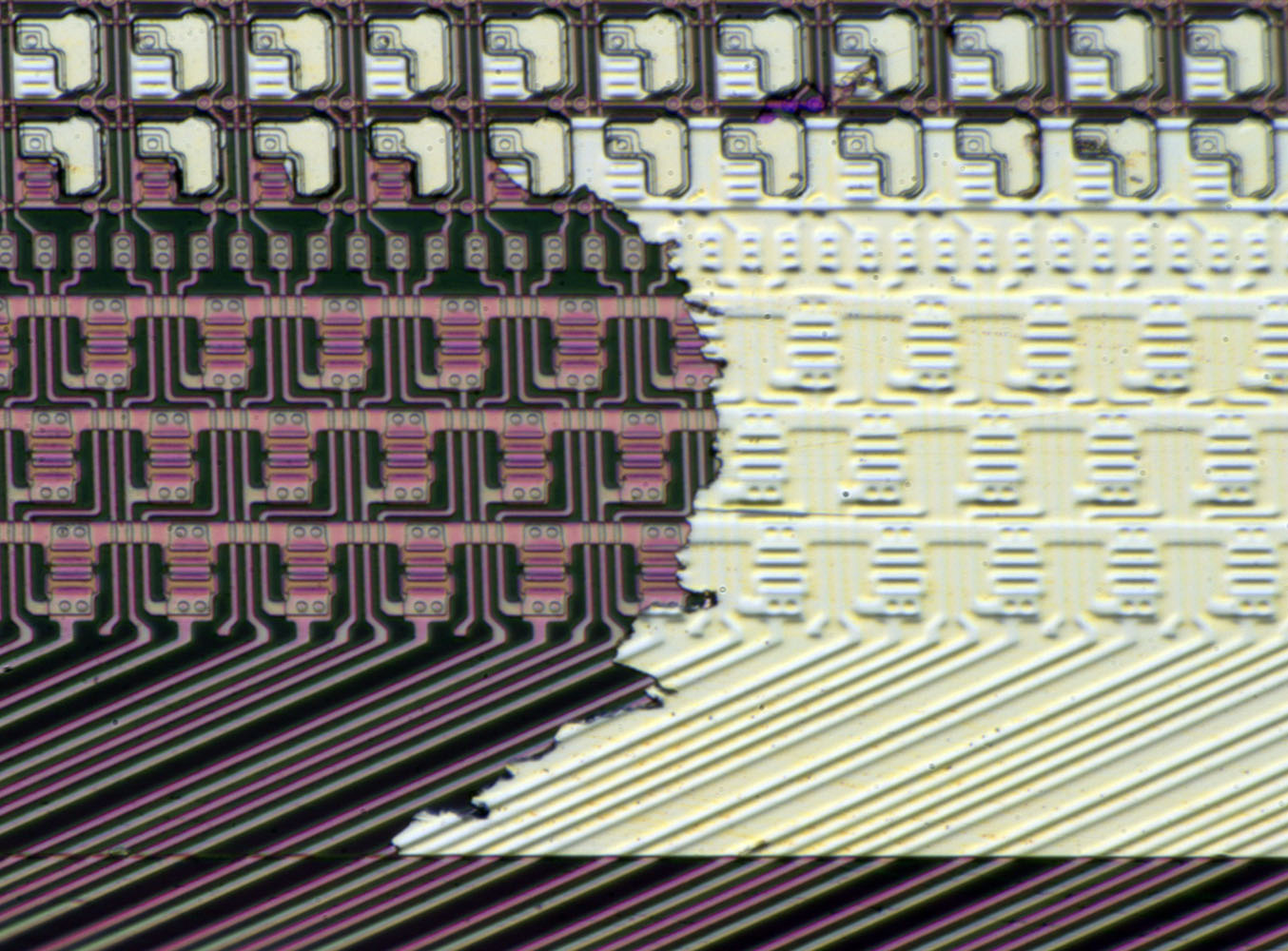
There seems to be a lack of metal on the lowest pixel row. In one place there is a huge amount of metal. Probably the lowest line is a dummy line like we have seen that in the DLP-Modul DMD1076 (https://www.richis-lab.de/DLP.htm) and in the Lepton 2.5 (https://www.richis-lab.de/Opto04.htm).


Fortunately here we can see the two transistors.


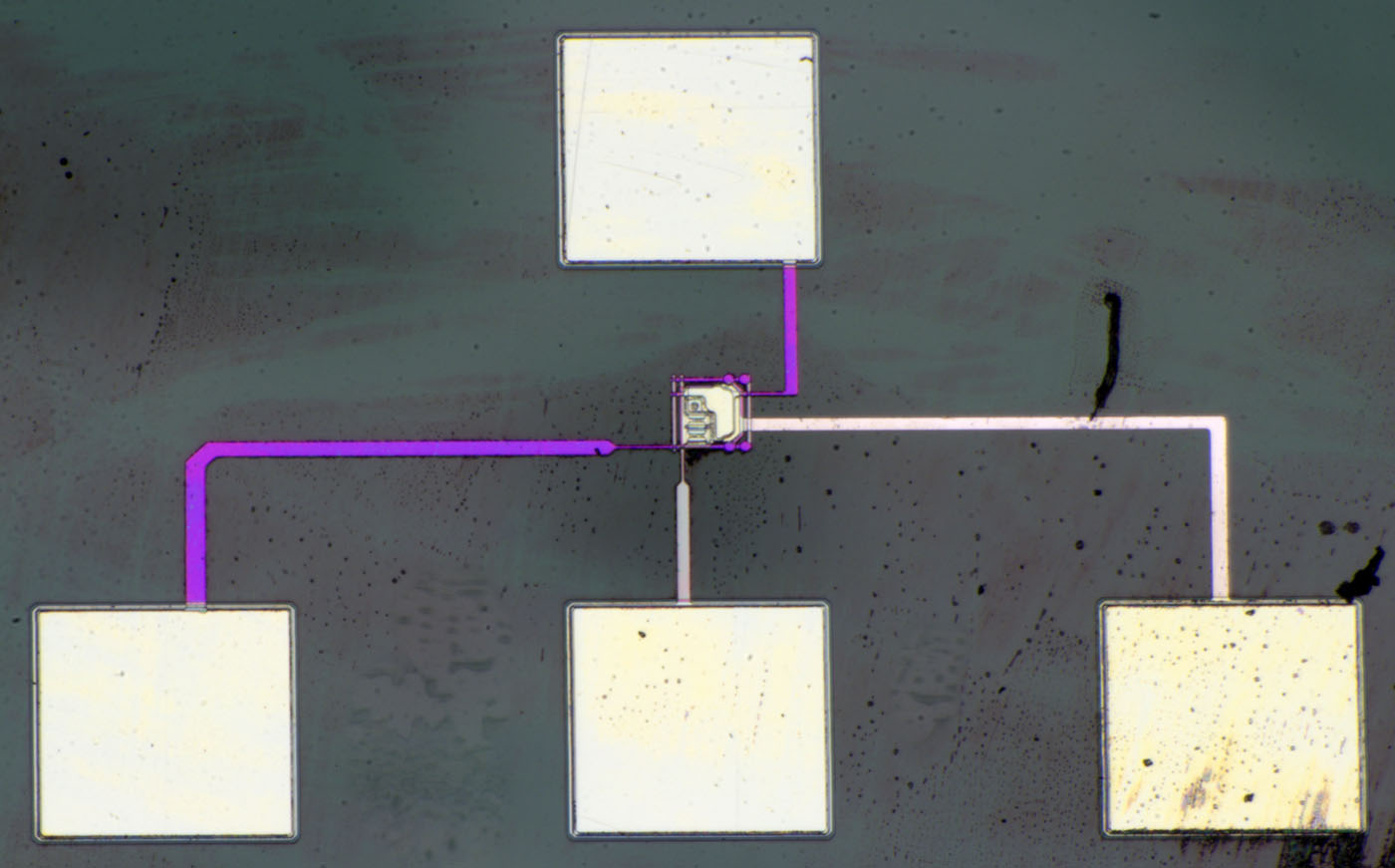
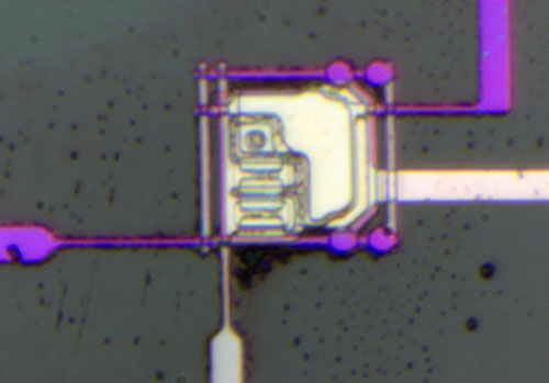
A test structure! With the bottom pad you can switch the pixel. The left pad supplies the pixel. The upper pad is the reference for the capacitor and the right pad is connected to the upper electrode.


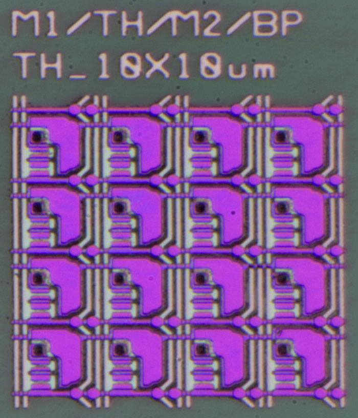
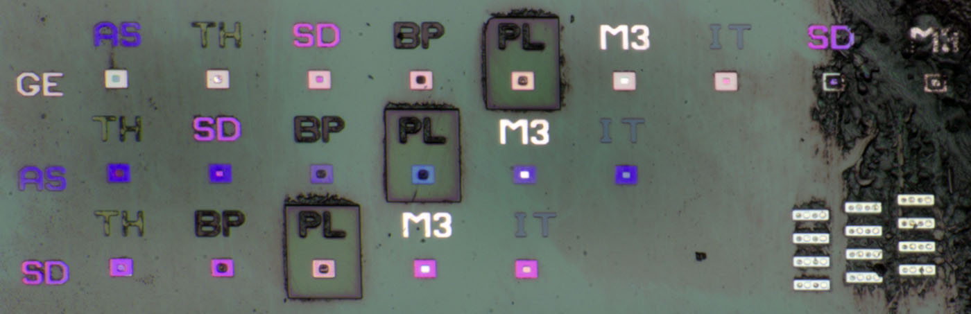
On the edge of the panel we have some nice test structures showing the construction of the panel.
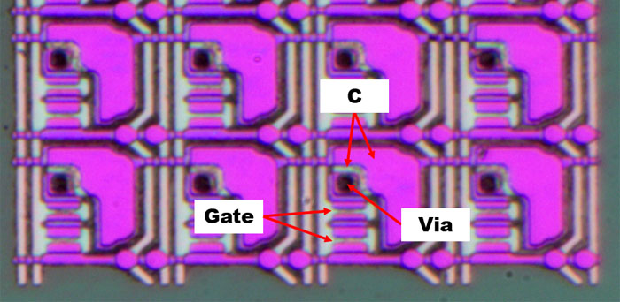
Here we see M1 and M2 showing us the metal parts of the MOSFETs.
TH probably stands for through hole and gives you 10µm vias. It seems that is a little too much.
I don´t know what BP means.


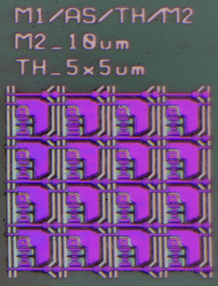
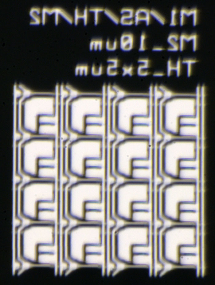
Here we have AS. That probably stands for amorphous silicon that is located in the MOSFET area.
Vias are smaller here. Looks good now.
It seems M2_10µm stands for a different transistor type. The contacts between the MOSFETs are smaller in this area.


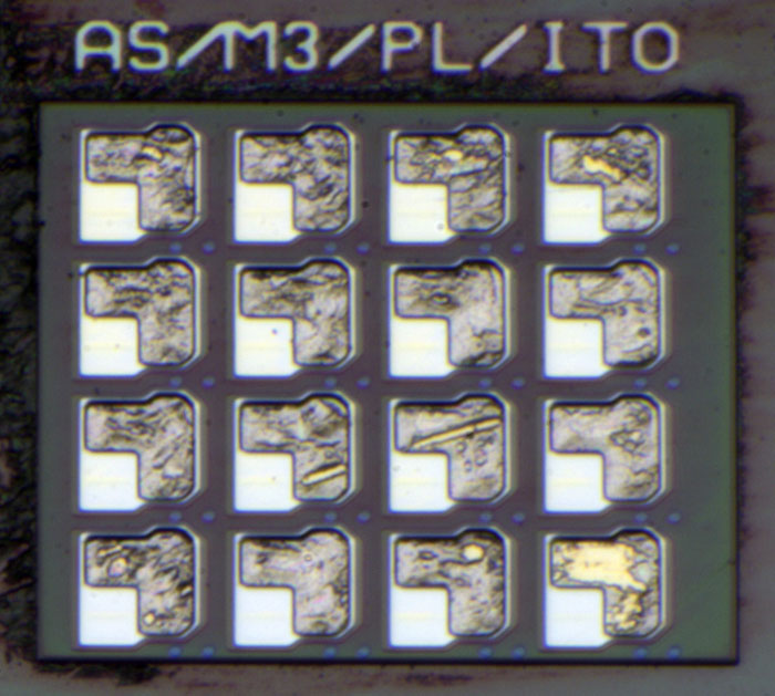
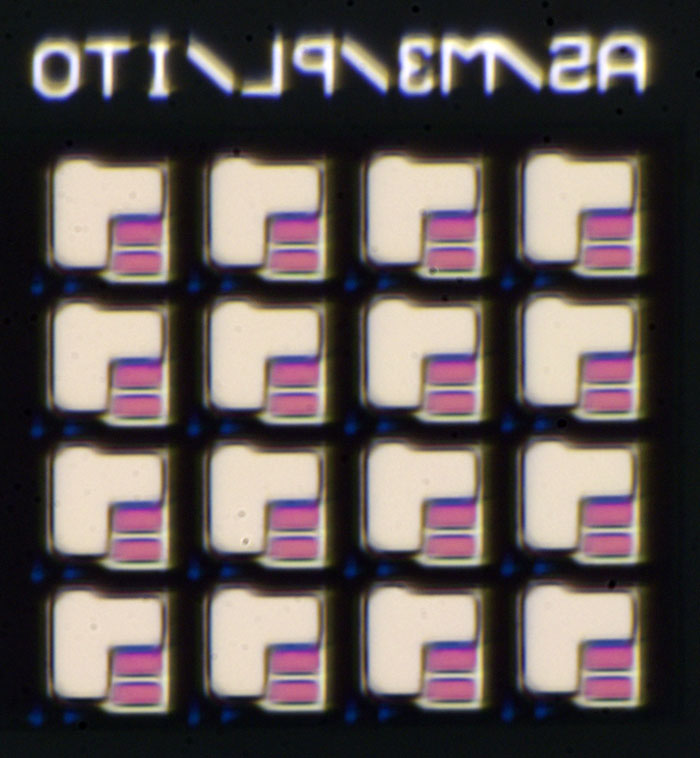
Here we see the uppermost metal layer M3. There is a lower part which increases the capacitance of the capacitor underneath. The capacitance is located between M2 and M1/M3.
The amorphous silicon looks reddish here.
Where the control lines cross each other there are blue dots. Perhaps these dots control whether or not the control lines have contact to each other.  :-//


https://www.richis-lab.de/eink01.htm

 :-/O
 
The following users thanked this post: edavid, doktor pyta, RoGeorge, Renate

Offline RoGeorge

  • Super Contributor
  • ***
  • Posts: 6185
  • Country: ro
Re: Optoelectronics - die pictures
« Reply #22 on: April 30, 2021, 08:55:26 am »
Looking at all those parallel traces on glass, I wonder if they can be used as a diffraction grate for a laser pointer, to project interference patterns on a wall.   ;D

Offline NoopyTopic starter

  • Super Contributor
  • ***
  • Posts: 1729
  • Country: de
    • Richis-Lab
Re: Optoelectronics - die pictures
« Reply #23 on: April 30, 2021, 11:49:48 am »
Looking at all those parallel traces on glass, I wonder if they can be used as a diffraction grate for a laser pointer, to project interference patterns on a wall.   ;D

That would definitely look interesting!  ;D


A small update: ITO stands for Indium Tin Oxide and that makes perfectly sense. It seems like there is a layer of ITO all over the area with slots on top of the electrodes. With this shielding the control lines don´t influence the pigment bubbles.  :-+

Offline NoopyTopic starter

  • Super Contributor
  • ***
  • Posts: 1729
  • Country: de
    • Richis-Lab
Re: Optoelectronics - die pictures
« Reply #24 on: May 10, 2021, 04:13:26 am »
VQC10...
https://www.richis-lab.de/Opto05.htm


I have a second VQC10 (4x 7x5-Dot-Matrix-Display built by the Werk für Fernsehelektronik Berlin).
It seems like this display is a development part like the first VQC10.


This part is already potted and has some more pins to get rid of the power loss.


The layout is similar to the first part but here we have four additional wide copper traces conducting heat from the LEDs to the pins at the bottom.


WF had problems with the bonding. The magazine Radio Fernsehen Elektronik 2/89 describes that in production they had up to two rework loops to get good parts.
In this VQC10 only the third segment is really bad.


That doesn´t look good...  :o


The Flip-Flop dies are newer:
01K710 => 03K710
A1/B1/C1/D1/F1/H1/I1/M1 => A7/B2/C7/D2/F2/H7/I7/M7


Here we have no option to adjust the current limitation resistor of the output stages.


They changed the LED type. The die is smaller (0,38mm). The active area also occupies a smaller fraction of the die. But the bondpad and bondwire interfere less with the light.


5µA  :-+


10µA


20µA


5mA
You can clearly see the two layer construction.


20mA  8)


https://www.richis-lab.de/Opto07.htm

 :-/O
 
The following users thanked this post: edavid, doktor pyta, RoGeorge, Miyuki, Renate


Share me

Digg  Facebook  SlashDot  Delicious  Technorati  Twitter  Google  Yahoo
Smf