OK, that's good to hear

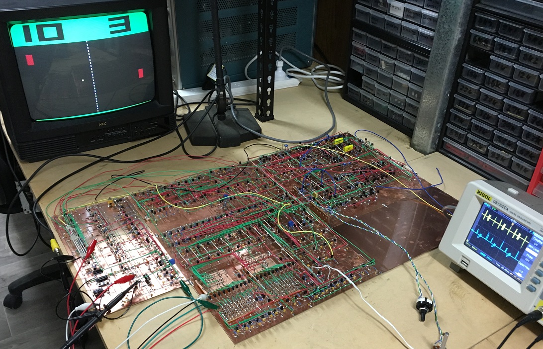
I finally got back to the video version this weekend. After a late night this evening the colour video circuitry is all soldered up. I still have to reroute the interconnecting wires neatly, but it's currently fully operational. I opted for a green scoreboard/boundary, red paddles, a yellow ball and a white court net/divider.
Of the currently assembled panel, the colour video generation circuitry occupies the 150mm X 300mm board on the bottom left. The currently vacant 150mm X 150mm space directly to the right of this board will sport the regulated power supply electronics (+/-5V & +/-15V). Actually there are two independent composite video channels/outputs on the video board. One is the colour channel for colour monitors/televisions and the other is a monochrome output in which the luma component is only ever one of two levels - zero (black) or full amplitude white. I soldered up this additional monochrome channel as the colour video signal rendered in a greyscale when viewed on a monochrome TV doesn't look as good. Red, for example, has a rather low-level luma component (30% of peak white), and the paddles appear quite dark on a B&W display. For the monochrome channel the discrete video components for the paddles, ball, court net, etc, are simply logically ORed together. In the colour channel they are processed by a luma (Y) matrix to satisfy the PAL standard; Y = 0.3R+0.59G+0.11B.
The blank PCB currently tacked onto the top right of the assembled panel will sport the sound effects/synth circuitry and the remainder of the games control logic. That's the next part to get soldered.
I must admit it's all beginning to look a little complimicated now.......

The colour channel:
The monochrome channel:


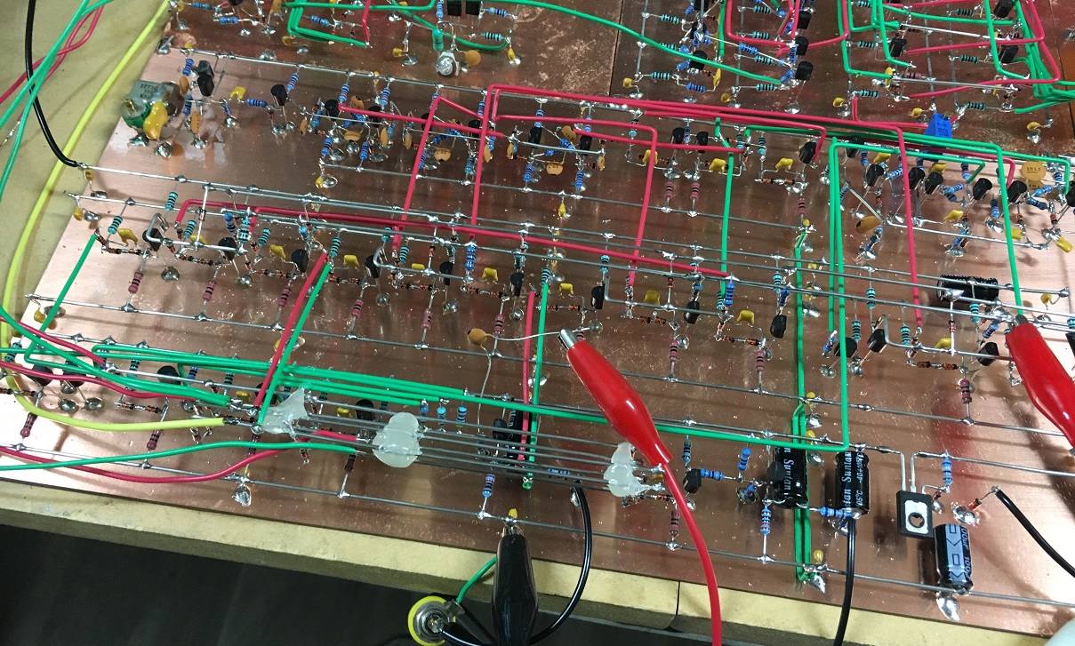
Video board: