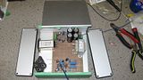
Hey all, i'm nearing the end of another audio project. This time a couple of Phono Preamps, and their respective power supplies.
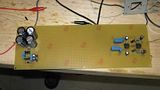
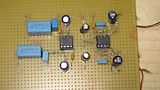
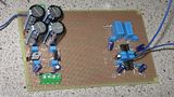
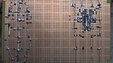
Here are some pictures...its all on breadboard, but instead of point to point with wire runs (like on my Tube Amp) i tried to do the layout so that i could make all the connections directly with component leads or with some solder bridges. I think my next project i might try etching and routing my first PCB
I do have some questions/issues
Each preamp-psu combo use exactly the same schematic (schematics courtesy of Elliot Sound Products - ESP) and while the layout is different in both of them, i am getting the same quirky issue with the PSU
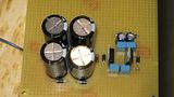
On both the PSU's i get a solid -15.04 V on the negative rail, but on the positive rail i get roughly 14.85 volts....i'm not sure why i'm short 150mv when i'm using voltage regulators....7815 and 7915 regulators. I did check the input voltage to the regulator, and while i forgot what it was, it didn't raise any red flags, i think it was at least 18 or 19 v (well above the dropout voltage for the regulator to give 15v out) but ill double check tonight.
Schematic is here
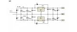
Its being fed by a 16V AC transformer...but runs a bit high, around 18-19v on idle, with a load still around 17vac
Any thoughts? or comments?
p.s One additional design question. The IEC power socket, is it worth it to use the one with the built in filter, as pictured, or just use a standard IEC socket to save space.


