Author Topic: pimp up grandma's clock with Nixie tubes  (Read 10346 times)

0 Members and 1 Guest are viewing this topic.

Offline FrankBussTopic starter

  • Supporter
  • ****
  • Posts: 2365
  • Country: de
    • Frank Buss
pimp up grandma's clock with Nixie tubes
« on: March 17, 2017, 04:42:41 pm »
I have already too many project, so let's start another one. I bought this broken clock and then looked for some Nixie tubes. There are nice ones at eBay. One of the best looking Nixie tube is the Z568M. Usually they cost more than $200 on eBay, and they get sold for this price, see e.g. this listing. Nothing wrong with it and the production quality is high, so it will probably last many years. But there is a new manufacturer, who creates a new version of this tube, Dalibor Farny, each one hand-made, and with 10 years warranty.

I bought some, and they are gorgeous. The packet arrived today:
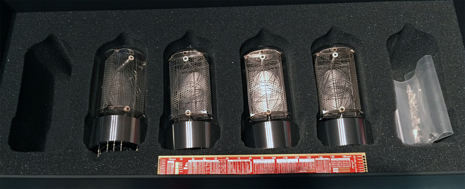


Bottom side:


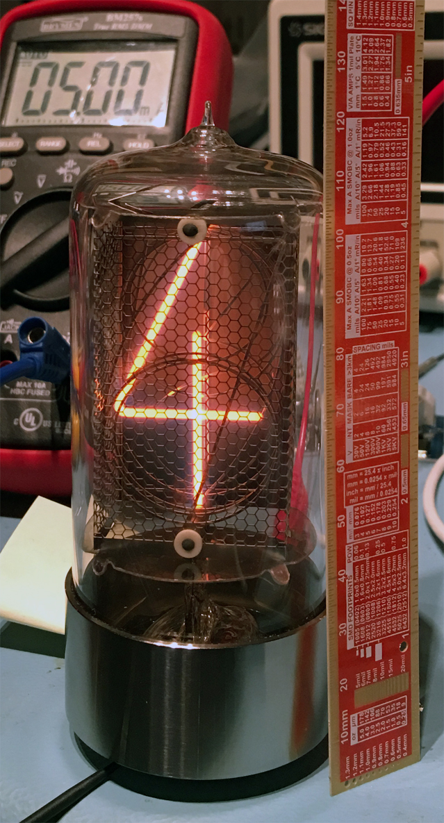
and a quick test, it looks so beautiful :-+


Now I'll design the circuit board for it.

Surprise: I just opened the clock and it comes with a built-in audio device :) This brings back memories, I remember the sound, my grandparents had such a clock (I think each full hour or at 12 o'clock: dong - dong - dong...). Will add some solenoids.


So Long, and Thanks for All the Fish
Electronics, hiking, retro-computing, electronic music etc.: https://www.youtube.com/c/FrankBussProgrammer
 
The following users thanked this post: Sjoertdb

Offline Zbig

  • Frequent Contributor
  • **
  • Posts: 927
  • Country: pl
Re: pimp up grandma's clock with Nixie tubes
« Reply #1 on: March 17, 2017, 04:57:08 pm »
I just had a thought that'd be cool if the nixie digits transitioned not quickly and cleanly but with some intentional (pseudo)random noise added for some duration. Imagine the pushbutton switch bounce type waveform applied for, say 300 ms during the transition so it's like "1-1-1-1-1-1-1-2-1-1-2-1-2-2-1-2-2-2-2-2-2-2-2-2". Not sure that would appeal to everyone but I'd personally like to have it at least as an option had I ever be building a nixie clock myself. I think it would add greatly to the steampunky feel, hinting at something mechanical, imperfect, slightly deteriorating. Unless of course it would be detrimental to the tubes' lifespan - then it's not worth considering.
« Last Edit: March 17, 2017, 05:01:44 pm by Zbig »
 

Offline bitseeker

  • Super Contributor
  • ***
  • Posts: 9057
  • Country: us
  • Lots of engineer-tweakable parts inside!
Re: pimp up grandma's clock with Nixie tubes
« Reply #2 on: March 17, 2017, 06:45:09 pm »
Great title, Frank. Looking forward to seeing this come together.

I hadn't heard of this tube builder before. Thanks for the link.
TEA is the way. | TEA Time channel
 

Offline FrankBussTopic starter

  • Supporter
  • ****
  • Posts: 2365
  • Country: de
    • Frank Buss
Re: pimp up grandma's clock with Nixie tubes
« Reply #3 on: March 17, 2017, 10:02:50 pm »
I just had a thought that'd be cool if the nixie digits transitioned not quickly and cleanly but with some intentional (pseudo)random noise added for some duration. Imagine the pushbutton switch bounce type waveform applied for, say 300 ms during the transition so it's like "1-1-1-1-1-1-1-2-1-1-2-1-2-2-1-2-2-2-2-2-2-2-2-2". Not sure that would appeal to everyone but I'd personally like to have it at least as an option had I ever be building a nixie clock myself. I think it would add greatly to the steampunky feel, hinting at something mechanical, imperfect, slightly deteriorating. Unless of course it would be detrimental to the tubes' lifespan - then it's not worth considering.

I even thought about using PWM to individually control the brightness and do interesting effects. It is possible with Nixie tubes, someone did it:


But I found one page where the tube didn't like it (in German) :

https://www.mikrocontroller.net/topic/308329

In summary: the Nixie tube got cloudy, because they think the PWM causes lots of ignitions with the PWM frequency, and with each ignition the anode sputters a bit of itself on the glass inside. I couldn't find any other reference to this effect, but it sounds plausible. So maybe better to drive it with a constant static voltage. But I'll add individual series resistors at the cathode side for each digit to adjust the relative brightness.
So Long, and Thanks for All the Fish
Electronics, hiking, retro-computing, electronic music etc.: https://www.youtube.com/c/FrankBussProgrammer
 

Online cncjerry

  • Supporter
  • ****
  • Posts: 1279
Re: pimp up grandma's clock with Nixie tubes
« Reply #4 on: March 17, 2017, 10:15:32 pm »
Interesting.  Ping Peter at Tubeclock.com.  Great guy but the way.

I thought his clocks used some type of either PWM or ramp to keep them from going off to on abruptly. I thought this was actually common with Nixies and had been thinking about asking him for a more immediate application which would be easier to visually sync with WWV, for instance. 

He wrote me a special PIC chip so I can feed it 1PPS from my GPSDO instead of using the crystal but I haven't installed it.  Before I blew up the high voltage and then the original PIC chip, that clock kept less than a second variance per year.  I am slowly getting in it dialed back in but it is still running a little slow.  Before changing the chip out for the 1PPS I want to see if it will keep the same accuracy.  Being a time nut, I was simply amazed with this clock's accuracy without discipline.

Anyway, Peter knows a lot about NIxie tube clocks and maintaining the lifespan of the tubes.

Nice work, BTW.
 

Offline McBryce

  • Super Contributor
  • ***
  • Posts: 2682
  • Country: de
Re: pimp up grandma's clock with Nixie tubes
« Reply #5 on: March 18, 2017, 12:53:07 pm »
It may have been the particular frequency he chose for the PWM or just dodgy nixie tubes. My Nixie Clock has been running for years on PWM which it also uses to fade-in/fade-out the digits and none of them have gone cloudy.

McBryce.
30 Years making cars more difficult to repair.
 

Offline FrankBussTopic starter

  • Supporter
  • ****
  • Posts: 2365
  • Country: de
    • Frank Buss
Re: pimp up grandma's clock with Nixie tubes
« Reply #6 on: March 18, 2017, 01:29:33 pm »
Sounds good, at which frequency do you run the PWM? I guess the higher the better (but then more switching loss) ?
So Long, and Thanks for All the Fish
Electronics, hiking, retro-computing, electronic music etc.: https://www.youtube.com/c/FrankBussProgrammer
 

Offline McBryce

  • Super Contributor
  • ***
  • Posts: 2682
  • Country: de
Re: pimp up grandma's clock with Nixie tubes
« Reply #7 on: March 18, 2017, 08:42:06 pm »
I don't remember the exact frequency I used, I'd need to dig out my documents, but it was somewhere around 1kHz and I remember having to fine tune this to something "uneven" because it was causing the tubes to "sing". However, the ideal frequency will probably depend on the tubes you use and the DC/DC you're using to create the HV.

McBryce.
30 Years making cars more difficult to repair.
 

Offline FrankBussTopic starter

  • Supporter
  • ****
  • Posts: 2365
  • Country: de
    • Frank Buss
Re: pimp up grandma's clock with Nixie tubes
« Reply #8 on: March 21, 2017, 02:54:26 am »
I photoshopped a first design idea:


And there is a Hackaday project for the Hackaday prize 2017 where I entered with this project:

https://hackaday.io/project/20474-antique-nixie-clock

One motto of the prize is "create a better life for all of us". It helps recycling old clocks, less pollution in landfills, so good for the environment, better life for all of us :)
So Long, and Thanks for All the Fish
Electronics, hiking, retro-computing, electronic music etc.: https://www.youtube.com/c/FrankBussProgrammer
 

Offline bitseeker

  • Super Contributor
  • ***
  • Posts: 9057
  • Country: us
  • Lots of engineer-tweakable parts inside!
Re: pimp up grandma's clock with Nixie tubes
« Reply #9 on: March 21, 2017, 04:40:37 am »
I like it. Could also try it with each pair of tubes a bit closer together. Also try them closer to the analog clock vs. centered between it and the edges. Sometimes clustering looks good, other times evenly spaced is better. See what feels right to you.
TEA is the way. | TEA Time channel
 

Offline FrankBussTopic starter

  • Supporter
  • ****
  • Posts: 2365
  • Country: de
    • Frank Buss
Re: pimp up grandma's clock with Nixie tubes
« Reply #10 on: March 21, 2017, 08:41:00 am »
I like it. Could also try it with each pair of tubes a bit closer together. Also try them closer to the analog clock vs. centered between it and the edges. Sometimes clustering looks good, other times evenly spaced is better. See what feels right to you.

You are right, and maybe more to the front, because otherwise the tubes are hidden behind the analog clock if you look at it from the side. And looks even nicer when it is more in one plane with the clock face.

So Long, and Thanks for All the Fish
Electronics, hiking, retro-computing, electronic music etc.: https://www.youtube.com/c/FrankBussProgrammer
 

Offline McBryce

  • Super Contributor
  • ***
  • Posts: 2682
  • Country: de
Re: pimp up grandma's clock with Nixie tubes
« Reply #11 on: March 21, 2017, 09:46:41 am »
I know it won't work with tubes that size, but I was expecting the tubes to be mounted inside the clock face?

McBryce.
30 Years making cars more difficult to repair.
 

Offline FrankBussTopic starter

  • Supporter
  • ****
  • Posts: 2365
  • Country: de
    • Frank Buss
Re: pimp up grandma's clock with Nixie tubes
« Reply #12 on: March 21, 2017, 12:57:33 pm »
Yes, would be too big inside, unless you want to stick it at the side like bull horns, but this would look odd.

Actually I have some of these tubes as well:

http://www.ebay.de/itm/131800949921

Maybe for a smaller wood clock this would look good inside on the clock face.
So Long, and Thanks for All the Fish
Electronics, hiking, retro-computing, electronic music etc.: https://www.youtube.com/c/FrankBussProgrammer
 

Offline bitseeker

  • Super Contributor
  • ***
  • Posts: 9057
  • Country: us
  • Lots of engineer-tweakable parts inside!
Re: pimp up grandma's clock with Nixie tubes
« Reply #13 on: March 21, 2017, 11:53:39 pm »
I like it. Could also try it with each pair of tubes a bit closer together. Also try them closer to the analog clock vs. centered between it and the edges. Sometimes clustering looks good, other times evenly spaced is better. See what feels right to you.

You are right, and maybe more to the front, because otherwise the tubes are hidden behind the analog clock if you look at it from the side. And looks even nicer when it is more in one plane with the clock face.


Yes, I like this arrangement very much. The relationship between the round base of the tubes and the curves of the front edge work well together, too. This looks perfect to me.  :-+ :-+ :-+

There's only one problem. Now I want one!
« Last Edit: March 21, 2017, 11:55:32 pm by bitseeker »
TEA is the way. | TEA Time channel
 

Offline FrankBussTopic starter

  • Supporter
  • ****
  • Posts: 2365
  • Country: de
    • Frank Buss
Re: pimp up grandma's clock with Nixie tubes
« Reply #14 on: March 22, 2017, 12:31:13 pm »
I contacted Peter from Tubeclock.com about PWM and his response might be useful for others as well:

Quote
Nixie tubes work just fine with PWM.  I do notice that the tubes that change frequently (i.e., the seconds tubes, as compared to the hours tubes) will tend to wear out a little more quickly on average. However, that's just a general tendency, and the variation due to which box of nixie tubes were used is much higher than the variation in tube life due to how many times the tube was turned on/off due to PWM dimming.  All the tubes will die eventually regardless.  Nixe tubes that see lots of PWM dimming live only slightly shorter lives on average, and will often have longer lives because other variables (beyond your control) are more important.

It is interesting that the tubes that change frequently wear out faster, so now the question is how high the PWM frequency should be, because I guess the lower it is, the more it is like a normal turn off/on?
So Long, and Thanks for All the Fish
Electronics, hiking, retro-computing, electronic music etc.: https://www.youtube.com/c/FrankBussProgrammer
 

Offline McBryce

  • Super Contributor
  • ***
  • Posts: 2682
  • Country: de
Re: pimp up grandma's clock with Nixie tubes
« Reply #15 on: March 22, 2017, 03:33:26 pm »
I wonder if a PWM with DC offset (on the "off" part) would be friendlier to the Nixies?

McBryce.
30 Years making cars more difficult to repair.
 

Offline james_s

  • Super Contributor
  • ***
  • Posts: 21611
  • Country: us
Re: pimp up grandma's clock with Nixie tubes
« Reply #16 on: March 25, 2017, 12:40:43 am »
Many nixie tubes will also audibly "sing" when PWM driven, so this is another issue to consider.
 

Offline bitseeker

  • Super Contributor
  • ***
  • Posts: 9057
  • Country: us
  • Lots of engineer-tweakable parts inside!
Re: pimp up grandma's clock with Nixie tubes
« Reply #17 on: March 25, 2017, 01:40:04 am »
Musical clock?
TEA is the way. | TEA Time channel
 

Offline FrankBussTopic starter

  • Supporter
  • ****
  • Posts: 2365
  • Country: de
    • Frank Buss
Re: pimp up grandma's clock with Nixie tubes
« Reply #18 on: March 28, 2017, 05:39:24 pm »
I implemented a quick test with a FPGA board. Now I can create any PWM frequency from 85 seconds period time, and up to 25 MHz, programmable by SPI. For each channel I can define an optional initial phase shift in cycles (this is useful to reduce current spikes, which can be a problem if you turn on all PWMs at the same time), the on-time, and the off-time. All values are 32 bit, and the counters for each channel are clocked with 50 MHz, for 10 channels in parallel (I love FPGAs). Maybe slightly overkill :D but now I can test different frequencies and fading algorithms easily. For example, this video shows it with a 6 kHz PWM frequency, which results in 13 bits resolution. The PWMs of the FPGA are programmed by an Arduino:


For calculating the duty cycle I used a logarithmic curve on the Arduino, as described here. I need only 256 steps for smooth on/off toggling, and looks even better in reality than on camera, but the resolution of 13 bits is required, because with 12 bits or lower you can start to see the steps when it is darker.

Now I need to build a prototype driver for a Nixie tube, LEDs are boring  :=\
So Long, and Thanks for All the Fish
Electronics, hiking, retro-computing, electronic music etc.: https://www.youtube.com/c/FrankBussProgrammer
 

Offline mbless

  • Regular Contributor
  • *
  • Posts: 227
  • Country: 00
Re: pimp up grandma's clock with Nixie tubes
« Reply #19 on: March 28, 2017, 09:00:20 pm »
Now I need to build a prototype driver for a Nixie tube, LEDs are boring  :=\

I'm interested to see what solution you come up with given Dave's version and all the other ones floating around online.
 

Offline marshallh

  • Supporter
  • ****
  • Posts: 1462
  • Country: us
    • retroactive
Re: pimp up grandma's clock with Nixie tubes
« Reply #20 on: March 29, 2017, 04:21:07 am »
I've done lots of research on PWMing nixies as part of my clock project. What I found was that my standard size tubes were able to be PWMed at a maximum of about 100 hz. Past that, the digits would not fully light and sometimes get stuck on or off (This is not an issue of my driving setup, it's the tubes themselves)

Additionally, there is a limitation on minimum and maximum duty cycles. The problems arise when the time spent on or off becomes less than about 10-15% the overall period. This basically means you cannot PWM the tube below that amount. This is because the gas takes time to ionize the gas around the cathode. If you use a high speed camera on the tube you can see the gas being ionized - it looks like lightning spreading across the sky.
Because the brightness is nonlinear, the eye is not able to detect the quantized brightness jump from 95-90% to full on (100% no pwm).

If you are using much larger tubes, you may have different limitations, it may be harder to PWM effectively based on the size. But I've only tested with one size tube here.


After writing code to account for these limtations, it's possible to hide these phenomena and get a nice looking result. I did PWM modules in verilog with crossfade support, and a NIOS cpu writes desired values to these registers to set the displays.
Verilog tips
BGA soldering intro

11:37 <@ktemkin> c4757p: marshall has transcended communications media
11:37 <@ktemkin> He speaks protocols directly.
 

Offline FrankBussTopic starter

  • Supporter
  • ****
  • Posts: 2365
  • Country: de
    • Frank Buss
Re: pimp up grandma's clock with Nixie tubes
« Reply #21 on: March 29, 2017, 05:27:57 pm »
Some years ago I used NIOS in a project. It was nice and using your own custom VHDL entities with a memory mapped interface from NIOS was useful, but the system builder was a bit complicated to use, and all the required manual steps and in the right order after you changed something was a pain. Now with modern ARM microcontrollers it is not cost effective, if you have some room on the PCB for an additional microcontroller. The price advantage for a smaller FPGA without the required gates for NIOS (except maybe in the smallest CPU configuration) is much bigger than a small microcontroller.

100 Hz doesn't sound much. Did you record some high speed videos of it? I'd love to see some video with the Chronos high speed camera Dave tested recently, with 21,000 fps, showing the effect of PWM or one ignition process. Meanwhile I ordered a cheap Casio Exilim camera, which promises 1,000 fps at a very low resolution. But should be good enough to see something, if 100 Hz is already the limit, maybe when single stepping the frames later.
So Long, and Thanks for All the Fish
Electronics, hiking, retro-computing, electronic music etc.: https://www.youtube.com/c/FrankBussProgrammer
 

Offline calexanian

  • Super Contributor
  • ***
  • Posts: 1881
  • Country: us
    • Alex-Tronix
Re: pimp up grandma's clock with Nixie tubes
« Reply #22 on: March 30, 2017, 12:19:22 am »
I love it. Keep it up. I want to see how those new nixies work out. I am thinking about starting a small tube company using basically the sales model they are using.
Charles Alexanian
Alex-Tronix Control Systems
 

Offline FrankBussTopic starter

  • Supporter
  • ****
  • Posts: 2365
  • Country: de
    • Frank Buss
Re: pimp up grandma's clock with Nixie tubes
« Reply #23 on: March 30, 2017, 01:40:48 am »
I love it. Keep it up. I want to see how those new nixies work out. I am thinking about starting a small tube company using basically the sales model they are using.

Good luck. From what I've seen, you should plan a year full time or so to develop and practice the art of tube making, and to buy a lot of expensive gear. This is how Dalibor Farny makes them:

So Long, and Thanks for All the Fish
Electronics, hiking, retro-computing, electronic music etc.: https://www.youtube.com/c/FrankBussProgrammer
 
The following users thanked this post: benst, tooki, cgroen, DaJMasta

Offline artag

  • Super Contributor
  • ***
  • Posts: 1064
  • Country: gb
Re: pimp up grandma's clock with Nixie tubes
« Reply #24 on: April 03, 2017, 09:40:01 pm »
I've done lots of research on PWMing nixies as part of my clock project. What I found was that my standard size tubes were able to be PWMed at a maximum of about 100 hz. Past that, the digits would not fully light and sometimes get stuck on or off (This is not an issue of my driving setup, it's the tubes themselves)


I used to work on calculators with Nixie tubes . They often had 12 or 16 digits (I guess people with enough money to afford them had large totals to calculate!). I'm pretty sure they were multiplexed, and at 100Hz they'd have flickered badly.

e.g. http://www.johnwolff.id.au/calculators/Canon/Canon1210External5.jpg

Maybe some nixies are faster reacting than others ? Or it depends what drivers you're using ?
« Last Edit: April 03, 2017, 09:42:48 pm by artag »


Share me

Digg  Facebook  SlashDot  Delicious  Technorati  Twitter  Google  Yahoo
Smf