Author Topic: Reading 2 digit 7 segments with ESP32  (Read 1818 times)

0 Members and 1 Guest are viewing this topic.

Offline StealthrtTopic starter

  • Regular Contributor
  • *
  • Posts: 82
Reading 2 digit 7 segments with ESP32
« on: May 12, 2022, 01:29:42 am »
I have been trying to contact a forum member (https://www.troublefreepool.com/threads/automation-of-intex-swg.228606/page-2#post-2128055) that has done a modification (https://www.troublefreepool.com/threads/automation-of-intex-swg.228606/) to his pool equipment in order to control it remotely instead of having to go to the box every time and check on the codes. His has released the source code on his github page (https://github.com/tonyflores1006/intex-swg-iot).

However, I have a different model than he does so I do not think his ESP32 code will work on mine.

His equipment contains a TM1650 for the 2 digit 7 segment display. I am unable to find out if my version has the TM1650 or something else.

His schematic looks like this:


I have all the components that are displayed in the schematic. I have the ESP32 and the Level shifter.


Another forum member had the same chip but some pins were different. His schematic looks like this:


So, since I do not have the same setup as they do is there any IC I can get that would make reading the 2 digit 7 segments easier than trying to read each led and determining what letter/number is being displayed? I can use the 4n25/35 optocoupler to "press" any of the 6 buttons and have an analog read for the 8 LEDs to determine which ones of those are on. The only trouble I foresee is the 2 digit 7 segments reading.

Note: Also posted to the following forums:
Reading 2 digit 7 segments with ESP32
https://www.electronicspoint.com/forums/threads/reading-2-digit-7-segments-with-esp32.297108/
https://forum.allaboutcircuits.com/threads/reading-2-digit-7-segments-with-esp32.186817/
https://www.electro-tech-online.com/threads/reading-2-digit-7-segments-with-esp32.163357/
https://www.electronics-lab.com/community/index.php?/topic/48746-reading-2-digit-7-segments-with-esp32/
« Last Edit: May 13, 2022, 01:29:31 pm by Stealthrt »
 

Offline ledtester

  • Super Contributor
  • ***
  • Posts: 3036
  • Country: us
Re: Reading 2 digit 7 segments with ESP32
« Reply #1 on: May 12, 2022, 03:10:16 am »
The ESP32 board appears to work by sniffing the I2C traffic to and from the TM1650.

The chip on your PCB looks like it could be a TM1650 - a lot of the pins seem to be connected as if it were that chip.

Here's the pinout of the TM1650:

1484653-0

and here I've annotated your PCB with where various pins are connected to:

1484659-1

You should check the annotations with a question mark to see if they are correct.

So the header pins on the PCB appear to be (from left to right):

1: SCL
2: SDA
3: Vcc
4: GND

Viewed from the top side of the board the pin order is: GND, Vcc, SDA, SCL.

This matches the ESP32 board header pinout with the difference that pins 3 and 4 are swapped.

More info on the TM1650:

https://components101.com/ics/tm1650-led-driver-ic


Offline StealthrtTopic starter

  • Regular Contributor
  • *
  • Posts: 82
Re: Reading 2 digit 7 segments with ESP32
« Reply #2 on: May 12, 2022, 03:14:25 am »
I appreshat you taking the time to draw that out ledtester.

I'll spend tomorrow hooking up the circuit and seeing what all I can find out.
 

Offline StealthrtTopic starter

  • Regular Contributor
  • *
  • Posts: 82
Re: Reading 2 digit 7 segments with ESP32
« Reply #3 on: May 13, 2022, 12:14:31 pm »
So I'm looking at my version of the ESP32 that I have (Known as the Lolin32)


And looking at their schematic I see that they call out GPIO 16, 17, 18 & 19. However, I do not have the same pin layout as they do...Go figure...
- GPIO 19 -> SWG main board clock
- GPIO 18 -> SWG main board data
- GPIO 17 -> Display board clock
- GPIO 16 -> Display board data


So, I take it my layout would be:

GPIO 19 -> GPIO 19 MISO
GPIO 18 -> GPIO 18 CLK
GPIO 17 -> GPIO 17 TX
GPIO 16 -> GPIO 16 RX

That look correct?
« Last Edit: May 13, 2022, 12:18:11 pm by Stealthrt »
 

Offline ledtester

  • Super Contributor
  • ***
  • Posts: 3036
  • Country: us
Re: Reading 2 digit 7 segments with ESP32
« Reply #4 on: May 13, 2022, 01:26:24 pm »
Can you provide the link to the github project?
 

Offline StealthrtTopic starter

  • Regular Contributor
  • *
  • Posts: 82
Re: Reading 2 digit 7 segments with ESP32
« Reply #5 on: May 13, 2022, 01:30:15 pm »
Can you provide the link to the github project?
Sorry I was unaware it did not place the url's where I had them. Its now corrected in the OP.
 

Offline ledtester

  • Super Contributor
  • ***
  • Posts: 3036
  • Country: us
Re: Reading 2 digit 7 segments with ESP32
« Reply #6 on: May 13, 2022, 01:59:45 pm »
The pin assignments appear to be defined here:

https://github.com/tonyflores1006/intex-swg-iot/blob/3701e1863e37f8e0390bd7e1345269a1b8db4305/main/IntexSWG.h#L24

Code: [Select]
#define clockPin        GPIO_NUM_19
#define dataPin         GPIO_NUM_18
#define clockDispPin    GPIO_NUM_17
#define dataDispPin     GPIO_NUM_16
#define powerRelayPin   GPIO_NUM_0

clockPin and dataPin are the pins that are monitored. The code also seems to talk to a TM1650 using dataDispPin and clockDispPin.

The monitoring code is here:

https://github.com/tonyflores1006/intex-swg-iot/blob/3701e1863e37f8e0390bd7e1345269a1b8db4305/main/IntexSWG.cpp#L168

You might want to extract that code and get it working first with a simple test app -- like just print the sniffed communications to the serial output.
 

Offline StealthrtTopic starter

  • Regular Contributor
  • *
  • Posts: 82
Re: Reading 2 digit 7 segments with ESP32
« Reply #7 on: May 13, 2022, 09:35:01 pm »
The pin assignments appear to be defined here:

https://github.com/tonyflores1006/intex-swg-iot/blob/3701e1863e37f8e0390bd7e1345269a1b8db4305/main/IntexSWG.h#L24

Code: [Select]
#define clockPin        GPIO_NUM_19
#define dataPin         GPIO_NUM_18
#define clockDispPin    GPIO_NUM_17
#define dataDispPin     GPIO_NUM_16
#define powerRelayPin   GPIO_NUM_0

clockPin and dataPin are the pins that are monitored. The code also seems to talk to a TM1650 using dataDispPin and clockDispPin.

The monitoring code is here:

https://github.com/tonyflores1006/intex-swg-iot/blob/3701e1863e37f8e0390bd7e1345269a1b8db4305/main/IntexSWG.cpp#L168

You might want to extract that code and get it working first with a simple test app -- like just print the sniffed communications to the serial output.

So I'm looking at my version of the ESP32 that I have (Known as the Lolin32)


And looking at their schematic I see that they call out GPIO 16, 17, 18 & 19. However, I do not have the same pin layout as they do...Go figure...
- GPIO 19 -> SWG main board clock
- GPIO 18 -> SWG main board data
- GPIO 17 -> Display board clock
- GPIO 16 -> Display board data


So, I take it my layout would be:

GPIO 19 -> GPIO 19 MISO
GPIO 18 -> GPIO 18 CLK
GPIO 17 -> GPIO 17 TX
GPIO 16 -> GPIO 16 RX

That look correct?
 

Offline ledtester

  • Super Contributor
  • ***
  • Posts: 3036
  • Country: us
Re: Reading 2 digit 7 segments with ESP32
« Reply #8 on: May 13, 2022, 11:21:18 pm »
The IntexSWG.cpp code appears to act as if it were a TM1650 on GPIO pins clockPin and dataPin and then talks to a real TM1650 on pins clockDispPin and dataDispPin. That is, it is meant to be inserted between your control board and the display board.

The clockDispPin and dataDispPin pair is not a TX/RX pair -- it's another I2C clock/data pair. You can use whatever GPIO pins you want as long as the pin definitions in the source code match what you're using.

I would first test the code by modifying this routine to emit the values of the statusDigits to via the serial port:

https://github.com/tonyflores1006/intex-swg-iot/blob/3701e1863e37f8e0390bd7e1345269a1b8db4305/main/IntexSWG.cpp#L411

And then I would program another microcontroller with a program that sends commands to a TM1650 -- like a TM1650 demo program. Hooking the two up will allow you to determine if the ESP32 code is correctly capturing and decoding the TM1650 traffic. The point is not to use your control board for initial testing. Also, if you write your own program you'll know exactly what is being sent to the TM1650 so you'll know if the ESP32 code is working correctly or not.


Offline StealthrtTopic starter

  • Regular Contributor
  • *
  • Posts: 82
Re: Reading 2 digit 7 segments with ESP32
« Reply #9 on: April 20, 2023, 12:24:41 pm »
Hey all I finally picked up this project again in hopes I can get it working before opening up my pool this year.

I have populated the pcb board with all the needed components and hooked the main board to it as well as the display board. However, when I turn on both the esp32 and main board I get nothing on the display? the display has 5v going to it so i know its not a connection issue.

When calling the rest api call http://192.168.1.219:8080/api/v1/intex/swg/status I get the following:
Code: [Select]
{
    "data": {
        "display": {
            "status": "ON",
            "brightness": 3,
            "current_code": ""
        },
        "status": {
            "power": "BUS_ERROR",
            "boost": "OFF",
            "sleep": "OFF",
            "o3_generation": "OFF",
            "pump_low_flow": "OFF",
            "low_salt": "OFF",
            "high_salt": "OFF",
            "service": "OFF"
        },
        "mode": {
            "working": false,
            "programming": false
        }
    }
}

I'm not sure what is causing the "BUS_ERROR". I had this both on a breadboard and on the official PCB and I get the same error on both. I have also hooked up both ends of the JST connectors to each other bypassing the esp32 and that also works as it should so its not the wiring issue causing it.

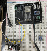
The front of my PCB looks like this:


And on the back I had to make modifications since my 5v/ground are swapped:


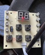
When I hook the display board up to the main board without the esp32 it displays a red dot on the led display which indicates its in off mode:


I am unable to get in touch with the original owner of this setup on the forum so I'm hoping someone here can help me figure out why its not working. :o


Share me

Digg  Facebook  SlashDot  Delicious  Technorati  Twitter  Google  Yahoo
Smf