Author Topic: Suggested low pass filter for a DAC  (Read 15154 times)

0 Members and 1 Guest are viewing this topic.

Online peter-hTopic starter

  • Super Contributor
  • ***
  • Posts: 3696
  • Country: gb
  • Doing electronics since the 1960s...
Suggested low pass filter for a DAC
« on: November 30, 2021, 07:53:33 am »
What would be the best approach for filtering this stepped sinewave

https://www.eevblog.com/forum/microcontrollers/32f417-a-cunning-way-to-reset-two-dma-pointers-from-an-edge-on-a-pin-etc/msg3841010/#msg3841010

I reckon Sallen-Key is probably the most effective, using just one op-amp.


I also need a gain of 2x (Ra=Rb) so C1 is likely 0.5xC2, but beyond that I am not sure, apart from trying out different values.

It is 400-500Hz and 64 steps per cycle. I can go to more steps and obviously that makes it easier but there are issues which drive 64.

I would like the phase lag variation between 300 and 600Hz to be less than 1 degree - because I am compensating for it by shifting the sin(x) table. I think this can be achieved but mainly by having the -3db rolloff well into the kHz range.
Z80 Z180 Z280 Z8 S8 8031 8051 H8/300 H8/500 80x86 90S1200 32F417
 
The following users thanked this post: ROT

Online T3sl4co1l

  • Super Contributor
  • ***
  • Posts: 21673
  • Country: us
  • Expert, Analog Electronics, PCB Layout, EMC
    • Seven Transistor Labs
Re: Suggested low pass filter for a DAC
« Reply #1 on: November 30, 2021, 08:39:56 am »
Phase or gain flatness: pick one.  Flatter phase in the passband leads to peaked gain at the transition frequency.  For a minimum-phase (standard all-pole) filter, anyway.

Flatter phase through the transition band, leads to soft gain rolloff.  Bessel is defined as minimum group delay, which in turn is defined as dPh/dF, so the phase changes more gradually for that type.  Note that phase still has to go through whatever range corresponds to the filter order (through transition to stop band), so you can't have flat (as in constant for all frequencies) phase, and filtering at the same time.

Or, you delay the passband to slow it to match the stopband delay, which obviously doesn't work all the way down to DC, but is technically applicable for bandpass filters.  You can have basically any phase shift at any frequency, using all-pass filters (while keeping flat gain), but not minimum phase: you can't speed anything up, of course, you have to slow everything else down.

The whole question seems academic since, as you say, you'll use a compensation table.  Maybe you just want the sharp corners to propagate correctly (when settings are changed suddenly)?

BTW you can get a 3rd order for free, put an RC out in front.  This changes the input impedance to the rest, so all the values have to change of course.

Also, MFB has better high frequency attenuation than SK (N-1 poles direct to GND, whereas SK has the feedforward path R1-C1), but is inverting.  (Since you're generating a sine, I don't see why it can't be complemented automatically, but whatever.)  MFB is also less sensitive to component values/tolerances than SK; but the difference isn't enough to matter for such a low order filter.  I have no problem using either, here -- this is just informational, really.  If you have further requirements, maybe it would motivate one over the other.

64x sounds like a rather low sample rate, especially for such a capable MCU.  But I haven't been following that thread, I don't know.  To get rid of the steps, you need a cutoff somewhere between [intended signal] and Fs/2, and enough attenuation by >Fs/2 to get the steps smoothed out (time-quantization noise down to noise floor, say).  This defines the filter order and sample rate.  Oversampling is great value to reduce analog requirements, allowing a lower order filter.

Tim
Seven Transistor Labs, LLC
Electronic design, from concept to prototype.
Bringing a project to life?  Send me a message!
 
The following users thanked this post: ROT

Online peter-hTopic starter

  • Super Contributor
  • ***
  • Posts: 3696
  • Country: gb
  • Doing electronics since the 1960s...
Re: Suggested low pass filter for a DAC
« Reply #2 on: November 30, 2021, 08:54:26 am »
I am trying to remove the steps.

The variation in the frequency will be very slow - over minutes or hours.

I can generate >1000 samples with the hardware, before running out of the DAC feed rate limit (DAC settling time). The reason for just 64 samples is because I am doing some amplitude variation and this needs recomputing the whole table. I won't be computing sin(x) of course; I will use a lookup table with 64 values and just doing a multiply; the 32F4 is 1 clock cycle for an int32 or single float multiply.

If something turns out to be really hard I can go to 100+ samples but would prefer not to.

What corner frequency would you suggest I start with?

Indeed I can get a 3rd pole wth just an RC, and the DAC is buffered in this case (with some sort of primitive x1 op-amp) which helps.

Also I wonder about which op-amp. Some reading suggests it needs to work at 100x the corner frequency, and the old LM358 is probably too slow. OP27 is better, OP37 better still but not stable below a 5x gain, but I want a single supply device. Obviously there are loads... The DAC output swings from +0.25V to +2.25V so the op-amp output will go from +0.5 to +4.5V. I have a 4.7V supply available :) or could use a DC-DC converter to get -15V and +15V.

« Last Edit: November 30, 2021, 09:07:13 am by peter-h »
Z80 Z180 Z280 Z8 S8 8031 8051 H8/300 H8/500 80x86 90S1200 32F417
 

Offline srb1954

  • Super Contributor
  • ***
  • Posts: 1091
  • Country: nz
  • Retired Electronics Design Engineer
Re: Suggested low pass filter for a DAC
« Reply #3 on: November 30, 2021, 09:10:38 am »
I am trying to remove the steps.

The variation in the frequency will be very slow - over minutes or hours.

I can generate >1000 samples with the hardware, before running out of the DAC feed rate limit (DAC settling time). The reason for just 64 samples is because I am doing some amplitude variation and this needs recomputing the whole table. I won't be computing sin(x) of course; I will use a lookup table with 64 values and just doing a multiply; the 32F4 is 1 clock cycle for an int32 or single float multiply.

What corner frequency would you suggest I start with?

If you using 64 steps per cycle theoretically there will be practically no harmonics until the 63rd and 65th providing the step sizes are exactly right and the step timing is exactly right. However, if there is any variation in the step timing (due to jitter) or inaccuracy in the step sizes (due to DAC quantiation error etc) then the lower harmonics will reappear in varying amounts.

Your best option would be to do an FFT on the unfiltered output to determine its harmonic content and determine how much that harmonic content has to be reduced by filtering. Knowing those parameters and your phase distortion requirements you could then pick a filter characteristic to suit.
 

Online peter-hTopic starter

  • Super Contributor
  • ***
  • Posts: 3696
  • Country: gb
  • Doing electronics since the 1960s...
Re: Suggested low pass filter for a DAC
« Reply #4 on: November 30, 2021, 09:55:00 am »
I can't get the LeCroy 3034 to do a meaningful FFT (the values I enter just keep resetting themselves) but my old Tek 2004B produces this


which shows the first harmonic at 500Hz x 64 as expected. It is almost 40db below the fundamental which I think is 10000x(?) below.

With 128 samples it is 2x further out as expected and is slightly smaller.

Z80 Z180 Z280 Z8 S8 8031 8051 H8/300 H8/500 80x86 90S1200 32F417
 

Offline Conrad Hoffman

  • Super Contributor
  • ***
  • Posts: 1930
  • Country: us
    • The Messy Basement
Re: Suggested low pass filter for a DAC
« Reply #5 on: November 30, 2021, 02:04:58 pm »
You can even do a 4th order filter with one opamp. Not sure about the numbers but would a higher order filter with the cutoff pushed out a bit further do less damage to the signal?
https://www.eevblog.com/forum/projects/third-order-filters-with-a-single-opamp-are-possible-after-all/
 

Online T3sl4co1l

  • Super Contributor
  • ***
  • Posts: 21673
  • Country: us
  • Expert, Analog Electronics, PCB Layout, EMC
    • Seven Transistor Labs
Re: Suggested low pass filter for a DAC
« Reply #6 on: November 30, 2021, 02:20:06 pm »
I am trying to remove the steps.

Great!  That's a good start.

How small must they be, before they appear to be "removed"?

Note: the answer cannot be zero, you must pick something nonzero.


Quote
I can generate >1000 samples with the hardware, before running out of the DAC feed rate limit (DAC settling time). The reason for just 64 samples is because I am doing some amplitude variation and this needs recomputing the whole table. I won't be computing sin(x) of course; I will use a lookup table with 64 values and just doing a multiply; the 32F4 is 1 clock cycle for an int32 or single float multiply.

Ah, so AM and FM then.  What update rate for each?  How fast (and smooth, or not) should they change?  What delay (between programmatic change, and output update) is allowable?

What's wrong with simply changing the DAC scale?  (I forget what exactly that MCU is capable of; this might be inapplicable given available features and requirements.)

How about dumping into a circular buffer every so often, and DMA --> DAC from there?  (I assume that's what the other thread is about, figuring out that sort of thing?)  The update simply occurs somewhere midstream, which could be per update of the buffer (polled or timed), or down to the sample (when the update event is known to a similar resolution)?  No need to rewrite the sine table, just get the change propagated into the buffer.  Nor any need to rewrite the buffer itself, unless you need instantaneous amplitude response somehow.

And there are still other methods, perhaps hardware involved, to provide very fast amplitude updates.  For example, run DAC into a digital pot, and update the pot (via SPI or parallel) with a fast interrupt (or even DMA) path, while the buffered sine wave stuff just goes on in the background as usual.


Quote
What corner frequency would you suggest I start with?

What phase flatness do you need?  Check the gain and phase curves of typical prototypes (Butterworth should be a fine starting point) and see how far down the curve (in the passband) you need to be.  Then go up the curve (into the stopband) and find where sufficient attenuation is reached to "eliminate" the steps.  That will be your sample rate.

If the ratio between the two is too large, try a higher order, or a flatter-phase prototype, and repeat.  (Chebyshev is peakier than Butterworth, but I don't think it's particularly flat in phase?  You may want to hand-tune things in SPICE or whatever and see what you can get.)


Quote
Also I wonder about which op-amp. Some reading suggests it needs to work at 100x the corner frequency, and the old LM358 is probably too slow. OP27 is better, OP37 better still but not stable below a 5x gain, but I want a single supply device. Obviously there are loads... The DAC output swings from +0.25V to +2.25V so the op-amp output will go from +0.5 to +4.5V. I have a 4.7V supply available :) or could use a DC-DC converter to get -15V and +15V.

Only needs to be GBW ~ Fc * Q.  For low order filters, Q is low, so GBW doesn't need to be much.

Another bonus of MFB is, the amp's own integrator characteristic acts in parallel with the feedback cap, so this can be factored out.  SK needs a bit extra, to deal with the gain dropoff of the amp stage (and consequent phase shift).

I would be surprised if LM358, or TLV2372, or OPA171 or friends, doesn't do the job.

Tim
Seven Transistor Labs, LLC
Electronic design, from concept to prototype.
Bringing a project to life?  Send me a message!
 

Offline Kleinstein

  • Super Contributor
  • ***
  • Posts: 14192
  • Country: de
Re: Suggested low pass filter for a DAC
« Reply #7 on: November 30, 2021, 02:54:47 pm »
The demand on the OP should not be so bad. The SK low pass filter is a bit worse, as the output gets hit by a current spikes through the FB capacitors. This gets less of a problem in the 3 rd oder configuration. The MFB form is supposed to be a bit less sensitive in this respect.

A flat phase in the passband is not very common requirement and 1 degree limit for the phase shift is already relatively tight. On the other side the corss over can be relatively high (e.g. 10 x the signal) with some 64 samples per second and thus theoretical the 1 st harmonics to worry about at 32 times the frequency. So testing in a simulation is a good idea. Some gain peaking like in the Chebychef version may help. One is not limited in Q to the standard types - values in between are OK too. There may be a lesser known one for flat phase.
 

Online peter-hTopic starter

  • Super Contributor
  • ***
  • Posts: 3696
  • Country: gb
  • Doing electronics since the 1960s...
Re: Suggested low pass filter for a DAC
« Reply #8 on: November 30, 2021, 03:26:34 pm »
"How small must they be, before they appear to be "removed"?"

I don't know ;) The signal needs to look clean on an analog scope, so perhaps 30x attenuation.

"so AM and FM then.  What update rate for each?  How fast (and smooth, or not) should they change?  What delay (between programmatic change, and output update) is allowable?"

FM, very slow. It is only to take out drift in the (crappy) oscillator feeding this thing (not my project).

AM, zero to max amplitude could happen in 1 second. It needs to appear smooth; I would estimate that during that one second I would need to generate the table 10-20 times. If I generate it at the maximum speed mentioned (1/400 sec) that will easily meet the requirement.

"What's wrong with simply changing the DAC scale?"

This is not a multiplying DAC. For those who know, this is essentially a form of LVDT emulation, and traditionally this is done with a four quadrant multiplying DAC. I am doing it wholly in this chip... The two DACs are just cheap on-chip 12-bit ones. Yes I could do an "instant" amplitude modulator post-DAC but it would need a digital (SPI in this case) control input, and I don't think it is needed.

"How about dumping into a circular buffer every so often, and DMA --> DAC from there? "

I am basically doing that. The DMA is double-buffered i.e. each time the transfer count gets to zero, it toggles the address pointer, and sets a "you can now fill the other buffer" bit. But I still need to be able to process the incoming signal (the one which requests the new amplitude) and fill that buffer with new sin(x) values, before the buffer is flipped back, which needs to be done in ~1ms to have a decent margin. And I have two channels of this to do. The two are always in phase, and always in phase with the input signal, but their amplitudes vary, from -sin(x) to +sin(x).

The whole thing runs in hardware. There is a counter which measures the input signal period, and which leaves that value (resolution ~1/5000) in a register, and there is a timer which triggers the DACs (whose period is periodically adjusted to match any frequency drift) and the DACs trigger a DMA. The only "software" in this whole "tracking wave generator" is an ISR which runs in 3us, on every zero crossing, and which resets the DMA pointers, to maintain sync. It's actually quite impressive to see it all running, and using up < 0.1% of CPU time :)

"What phase flatness do you need?"

I did some digging around - there is a Japanese site for filter simulation - and it looks like < 1deg delay is easy to achieve if the rolloff is say 10x the base i.e. ~4kHz. I will just need to birdsnest this and see... In fact, with 64 samples, if I go for a delay of 360/64 = 5.6 degrees then I can compensate for that with a 1 sample shift, which is easy (I am already doing a 2 sample shift due to the obscure reason mentioned in the other thread). And to get a 5+ deg delay you will be running the rolloff frequency pretty close to the base frequency.

"I would be surprised if LM358, or TLV2372, or OPA171 or friends, doesn't do the job."

The 358 won't quite do it because the +2.25V input is a bit tight with a +4.7V rail, and it won't do x2 gain (+4.5V max output) with a 4.7V rail. What the 358 does do is Vcm down to GND, and the output also swings all the way down (but below about +1V Vout is has almost no drive capability). I need a reasonably decent output drive because it may be driving a few m of cable.

As suggested earlier, an RC "pre-filter" before this filter
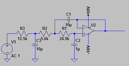


will give me a "free pole" but importantly should much reduce the op-amp BW requirement because one is taking out the really high harmonics. It will also take out the MHz-level crap which anything coming out of a "CPU board" is full of. I actually have a 16-bit ADC subsystem on this board and getting the noise down on that was a real challenge; the inputs had to be heavily filtered passively, and the whole circuit is galvanically isolated.

I have picked the TSV912AIDR - for rail to rail input and output, good BW, and an SO-8 package which is easy to birdsnest.

I don't have a simulator setup, unfortunately (used to have an analog sim many years ago).

What I don't understand is the need for precise component values. I mean, if one stage rolls off at say 4kHz and the one after it rolls off at 5kHz, does it matter? The S-K 2-pole config, with a gain of 1, "can't possibly be critical", but maybe at higher gains it is.

My plan was to make the 1st (passive) stage with a much lower Zout so the loading on it is not big (R3 in above diagram being maybe 1k only).

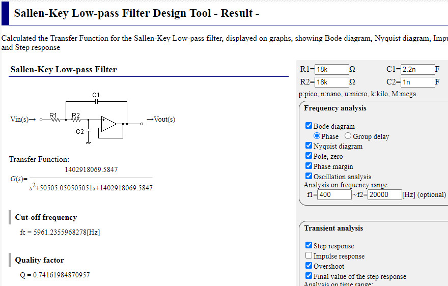
Playing around here
http://sim.okawa-denshi.jp/en/OPstool.php

with these values


I get 5.3deg phase delay at 400Hz and 6.5deg at 500Hz which is not far off the 5.62deg achievable with a 1 sample DAC table shift, and these are the two frequency limits of main interest.

What I don't have a sim for is a) the extra RC lowpass stage before this and b) a gain of 2x (but AIUI the 2x gain is simply taken care of by making C1 half the value and that keeps the curves the same).

« Last Edit: November 30, 2021, 04:21:05 pm by peter-h »
Z80 Z180 Z280 Z8 S8 8031 8051 H8/300 H8/500 80x86 90S1200 32F417
 

Online mawyatt

  • Super Contributor
  • ***
  • Posts: 3253
  • Country: us
Re: Suggested low pass filter for a DAC
« Reply #9 on: November 30, 2021, 04:25:18 pm »

A flat phase in the passband is not very common requirement and 1 degree limit for the phase shift is already relatively tight.

Obviously you haven't worked around digital communications where linear phase and flat group delay are as important as passband ripple and stop band rejection, where both Amplitude and Phase/Group Delay adversely impact Bit Error Rates (BER). Massive efforts are put forth to achieve acceptable phase, group delay and amplitude responses and often are achieved with complex "equalizers". Since all analog filters are by definition IIR, digital FIR filters/equalizers are often employed to create an overall system level transfer function which has an acceptable BER performance. Many designers will focus on the analog amplitude characteristics, especially stop band where aliasing is handled since these are pre-digitization, then utilize a digital FIR filter to correct the usual unpleasant passband phase-group delay responses that result from being neglected in the analog domain. As we try and cram more digital bits into a given limited BW, the effects of Phase and Group Delay responses become even more critical in the never ended battle to get more reliable information thru a limited bandwidth channel!!

Quote
There may be a lesser known one for flat phase.

The prior mentioned Bessel is a maximally flat group delay filter function, like the Butterworth is in amplitude. There are also analog filters that go between these two maximally flat limits, think the Gaussian and equiripple Chebyshev fall into this category. We often selected inverse Chebyshev in the advanced digital comm systems we developed, but that discussion is for another topic.

BTW the stop band "shoot thru problem" with Sallen-Key filters can be improved by loading the output Op-Amp with a resistor to Vee, this causes the output NPN or NMOS device to be biased more "On" and thus exhibits a lower open and closed loop output impedance.

Best,
Curiosity killed the cat, also depleted my wallet!
~Wyatt Labs by Mike~
 

Online peter-hTopic starter

  • Super Contributor
  • ***
  • Posts: 3696
  • Country: gb
  • Doing electronics since the 1960s...
Re: Suggested low pass filter for a DAC
« Reply #10 on: November 30, 2021, 04:31:36 pm »
I very easily got a very flat enough group delay with the above mentioned sim site, but I actually need a fairly flat phase lag - because I am trying to cancel out the phase lag by shifting the DAC feeding table, and with 64 samples I am stuck with 360/64 of a degree resolution there.

Best I can do, around the 5.6deg figure, are the above values and the 5.9kHz cutoff.

It will be good enough for this application, but if there is an easy improvement it would be nice :)

The  "shoot thru problem" is what I think drives the need for a good fast op-amp. No good doing an active filter with an op-amp which can't work at the frequencies you are trying to get rid of :) But hopefully choosing an op-amp which has a decent output stage helps. TSV911:


Maybe Class A would be better - which is what a pullup does, basically.

I am beginning to see that going for 128 samples per cycle would help :) BTW it doesn't need to be a power of 2.
« Last Edit: November 30, 2021, 04:38:50 pm by peter-h »
Z80 Z180 Z280 Z8 S8 8031 8051 H8/300 H8/500 80x86 90S1200 32F417
 

Online mawyatt

  • Super Contributor
  • ***
  • Posts: 3253
  • Country: us
Re: Suggested low pass filter for a DAC
« Reply #11 on: November 30, 2021, 04:44:44 pm »
@ Peter,

If I understand above, a constant phase delay implies a time delay that varies inversely with frequency of generation? IS this correct?

Best,
Curiosity killed the cat, also depleted my wallet!
~Wyatt Labs by Mike~
 

Online peter-hTopic starter

  • Super Contributor
  • ***
  • Posts: 3696
  • Country: gb
  • Doing electronics since the 1960s...
Re: Suggested low pass filter for a DAC
« Reply #12 on: November 30, 2021, 04:48:20 pm »
Yes; that would be ideal.

I can do 360/64 or at a push 360/128, degrees.

The S-K filter appears to do something like that - presumably because one is approaching the corner so there must be a slope of some sort.
Z80 Z180 Z280 Z8 S8 8031 8051 H8/300 H8/500 80x86 90S1200 32F417
 

Online mawyatt

  • Super Contributor
  • ***
  • Posts: 3253
  • Country: us
Re: Suggested low pass filter for a DAC
« Reply #13 on: November 30, 2021, 04:51:48 pm »
Also the shoot thru problem with SK is due the the fact that the closed loop output impedance "looks" inductive due to the roll off of the open loop gain. Bias loading the output causes the open loop impedance to start lower.

Here's a 3rd order Butterworth we published eons ago that uses Equal Value Components, which makes realizing easier. It does use multiple Op-Amps tho, but these may be available in a quad package. You can get by with 2 Op-Amps by moving the first order to the output of the last Op-Amp, but you lose the advantage of the passive first order at the input , and no Op-Amp output at the filter output.

Best,

Edit: You might look to a 2nd, 3rd or 4th order Gaussian (approximation) filter for the 1/f group delay effect. See image below from Zverev.
« Last Edit: November 30, 2021, 05:28:58 pm by mawyatt »
Curiosity killed the cat, also depleted my wallet!
~Wyatt Labs by Mike~
 

Online ejeffrey

  • Super Contributor
  • ***
  • Posts: 3717
  • Country: us
Re: Suggested low pass filter for a DAC
« Reply #14 on: November 30, 2021, 05:56:26 pm »
I very easily got a very flat enough group delay with the above mentioned sim site, but I actually need a fairly flat phase lag - because I am trying to cancel out the phase lag by shifting the DAC feeding table, and with 64 samples I am stuck with 360/64 of a degree resolution there.

I'm not quite sure what you mean here.  A flat group delay is just a constant time delay, equivalent to a fixed # of samples delay.  Low phase delay can matter in high bandwidth feedback loops since it affects stability but in a normal waveform generation applications it doesn't matter at all since the start time is effectively arbitrary.  Are you sure that is what you need? 
 

Online peter-hTopic starter

  • Super Contributor
  • ***
  • Posts: 3696
  • Country: gb
  • Doing electronics since the 1960s...
Re: Suggested low pass filter for a DAC
« Reply #15 on: November 30, 2021, 09:04:30 pm »
Yes - because I am compensating for the filter delay by shifting the DAC table along by 1 sample (actually, potentially a multiple of samples) and the width of a sample is some fixed proportion of a cycle period.

If I am running with 64 samples per cycle then each sample is 5.625 degrees long - regardless of the frequency being generated.

I guess this is a bit weird since probably most people building filters want a constant group delay, not a constant phase shift.

BTW I have done more of the code and using a precomputed sin(x) table I am able to compute a 128-sample DMA-> DAC table in just 15us which is negligible, so there is no performance issue at 128 samples, and the waveform looks pretty clean:


Using a S-K filter with a 43.kHz corner, I am getting about 5.5 deg of phase shift which is close to 2 DAC samples.
« Last Edit: November 30, 2021, 09:28:30 pm by peter-h »
Z80 Z180 Z280 Z8 S8 8031 8051 H8/300 H8/500 80x86 90S1200 32F417
 

Online ejeffrey

  • Super Contributor
  • ***
  • Posts: 3717
  • Country: us
Re: Suggested low pass filter for a DAC
« Reply #16 on: November 30, 2021, 09:53:05 pm »
I see, so you are doing frequency modulation by changing the sample rate?
 

Online peter-hTopic starter

  • Super Contributor
  • ***
  • Posts: 3696
  • Country: gb
  • Doing electronics since the 1960s...
Re: Suggested low pass filter for a DAC
« Reply #17 on: November 30, 2021, 10:09:19 pm »
Yes. The sample width is determined by a timer running at 84MHz, so it has a reasonably large time constant (about 1300). Constant number of DAC samples per cycle, regardless of the frequency.
Z80 Z180 Z280 Z8 S8 8031 8051 H8/300 H8/500 80x86 90S1200 32F417
 

Online T3sl4co1l

  • Super Contributor
  • ***
  • Posts: 21673
  • Country: us
  • Expert, Analog Electronics, PCB Layout, EMC
    • Seven Transistor Labs
Re: Suggested low pass filter for a DAC
« Reply #18 on: November 30, 2021, 11:31:20 pm »
Why shift something so gross as the whole DAC table?  Why not change the phase accumulator by small offset (DDS)?

Tim
Seven Transistor Labs, LLC
Electronic design, from concept to prototype.
Bringing a project to life?  Send me a message!
 
The following users thanked this post: SiliconWizard

Online ejeffrey

  • Super Contributor
  • ***
  • Posts: 3717
  • Country: us
Re: Suggested low pass filter for a DAC
« Reply #19 on: December 01, 2021, 12:24:18 am »
I see.  That isn't ideal for filtering because the nyquist frequency changes when you change operating frequency.  Your filter has to pass the highest frequency you generate while blocking the alias from the lowest sample rate you will use.  Since you have a relatively large oversampling ratio and a small frequency range you can probably make it work, but you are making it harder on yourself than if you used a fixed sample frequency and a constant group delay filter.  The downside is that it is potentially more resources than using a fixed buffer of samples and just varying the sample timer.  A standard NCO implementation is to have a phase accumulator that increments a set amount every cycle, then take the most significant N bits of the accumulator as an index for a pre-computed table.  You only need to store the table for the range 0..pi/2, so a 10 bit table only has 256 entries which is not usually prohibitive.  At your ~ 10 kHz sample rate most microcontrollers should be able to do the phase accumulation, lookup, and amplitude scaling in real time.  This also makes it trivially easy to implement a phase shift with a single addition.

But it sounds as if you have found an acceptable solution for your needs, if it works then I guess that's good enough.
 

Online peter-hTopic starter

  • Super Contributor
  • ***
  • Posts: 3696
  • Country: gb
  • Doing electronics since the 1960s...
Re: Suggested low pass filter for a DAC
« Reply #20 on: December 01, 2021, 02:41:57 am »
I am not doing this with DDS. I have a timer triggering a DAC which in turn triggers DMA to fetch the value from RAM and that loads up the DAC.

It is no doubt true that my reference frequency tracking mechanism could be much smarter. I could make tiny adjustments to the counter in the timer, for example. Currently I just load the freshly calculated auto-reload value into the timer.

I really don't think this is an issue however. I do need to track the input phase (align the zero crossings) but the only reason for tracking the input frequency is because the source is usually fairly primitive and drifts around a bit, over minutes or hours. And obviously if one doesn't track the input frequency then eventually you will end up with a big notch at the trailing end of the cycle :)

Yes indeed what I have works as far as the sinewave generation goes. I've spent a number of days chasing various subtle issues, to do with e.g. some registers not being writable while say a timer is running, and disabling the timer causes one artefact while doing something else causes another... I have now settled on a generator design which is running totally in hardware, with the only CPU load being a very short (about 3us) ISR at every +ve edge of the 400-500Hz input waveform. I still have an artefact where the first two DAC samples output after the zero crossing are equal (!); this is due to double buffering somewhere which is losing one DAC update (a hypothesis was by someone in the other thread) but while this is visible on a scope, with 128/256 samples per cycle you struggle to see it, and it leaves absolutely no trace whatsoever on a spectrum analysis of the DAC output so it will be completely immaterial after any filtering.

The simplest way to compensate for a filter delay is to rig up the filter so the delay is roughly one sample period, and shift the table by that much. I am already having to shift the table by 2 places due to double buffering on the DAC (no evident way to disable that, and you would never design such a stupid circuit if you were designing a wave generator yourself, with a DAC chip, because it is completely pointless).

The spec on what I am trying to emulate (something out of the 1970s) calls up a phase shift better than 10 degrees, which is atrocious, and I suspect some kit which is decoding this (probably in software) is actually a lot more fussy, so I am trying to do a lot better. I am readily achieving sync of 1 degree now.

I've done tons of analog since the 1970s (top grade audio, ppm-stability PSUs, etc) but never looked at filters properly, so this has been an interesting experience. It looks like there isn't a filter which does a constant phase delay - other than by selecting the rolloff so the phase delay is constant because it is negligible :)
« Last Edit: December 01, 2021, 03:00:34 am by peter-h »
Z80 Z180 Z280 Z8 S8 8031 8051 H8/300 H8/500 80x86 90S1200 32F417
 

Online T3sl4co1l

  • Super Contributor
  • ***
  • Posts: 21673
  • Country: us
  • Expert, Analog Electronics, PCB Layout, EMC
    • Seven Transistor Labs
Re: Suggested low pass filter for a DAC
« Reply #21 on: December 01, 2021, 11:39:21 am »
Right, in general, phase goes up with frequency; how much, is given by the group delay (give or take some funny business dis/ambiguating phase and group delays I think), and in a continuous system (transmission lines or free waves, as opposed to this lumped-element RLC system) the delay is a true causal delay, at whatever the speed of light is.  Delay meaning, phase shift exactly proportional to distance and frequency.  We can only have constant phase either with additional delay added for low frequencies to compensate (in which case, in finitely many bands, depending on how fancy we want to build the all-pass filter), or sufficiently near DC that we don't care about the real delays (which is the case here, up to the filter of course).

I don't get the reluctance for a DDS, you can run one into a buffer just fine.  It's preferable on a platform like that anyway, queue up a bunch of outputs, sit back and relax a while, repeat.  It doesn't have to run perfectly in real time, it just does whatever it does from sample to sample, and the DMA+DAC syncs it to real time.  Also solves your timer-shittiness problems, that timer issue doesn't sound like something that should happen in the first place, but eh when you need workarounds, you'll take options, right?

Tim
« Last Edit: December 01, 2021, 11:43:27 am by T3sl4co1l »
Seven Transistor Labs, LLC
Electronic design, from concept to prototype.
Bringing a project to life?  Send me a message!
 

Online mawyatt

  • Super Contributor
  • ***
  • Posts: 3253
  • Country: us
Re: Suggested low pass filter for a DAC
« Reply #22 on: December 01, 2021, 02:36:39 pm »
Since this is a created file for a sine wave from a DAC and then analog filtered if I understand correctly. If correct, one could implement a FIR filter before the DAC that compensates for the analog filter and creates the desired overall constant phase response at the output. Kind of like what I mentioned above about the phase and group delay response being very important in digital comm systems.

So in effect, equalizing the analog filter & desired phase response before the digital to analog conversion, and doing so in the digital domain where FIR filters/equalizers are possible!

Best,
Curiosity killed the cat, also depleted my wallet!
~Wyatt Labs by Mike~
 

Online gf

  • Super Contributor
  • ***
  • Posts: 1170
  • Country: de
Re: Suggested low pass filter for a DAC
« Reply #23 on: December 01, 2021, 03:23:44 pm »
Or even simpler, just fill the buffer with phase-adjusted samples (compensating the filter's phase response at the current frequency), given that the frequency changes so slowly that assuming a constant frequency and phase for the duration of one buffer is a sufficient approximation. A pre-calculated sine table with 512 entries is sufficient for 0.7° resolution, and 4k entries enable a resolution of < 0.1°.
 

Online T3sl4co1l

  • Super Contributor
  • ***
  • Posts: 21673
  • Country: us
  • Expert, Analog Electronics, PCB Layout, EMC
    • Seven Transistor Labs
Re: Suggested low pass filter for a DAC
« Reply #24 on: December 01, 2021, 04:00:10 pm »
Or even simpler, just fill the buffer with phase-adjusted samples (compensating the filter's phase response at the current frequency), given that the frequency changes so slowly that assuming a constant frequency and phase for the duration of one buffer is a sufficient approximation. A pre-calculated sine table with 512 entries is sufficient for 0.7° resolution, and 4k entries enable a resolution of < 0.1°.

Well yeah that's what he said, as I understand it -- albeit on the granularity of single samples, which is pretty coarse at the proposed sample rate.

Tim
Seven Transistor Labs, LLC
Electronic design, from concept to prototype.
Bringing a project to life?  Send me a message!


Share me

Digg  Facebook  SlashDot  Delicious  Technorati  Twitter  Google  Yahoo
Smf