"How small must they be, before they appear to be "removed"?"
I don't know

The signal needs to look clean on an analog scope, so perhaps 30x attenuation.
"so AM and FM then. What update rate for each? How fast (and smooth, or not) should they change? What delay (between programmatic change, and output update) is allowable?"
FM, very slow. It is only to take out drift in the (crappy) oscillator feeding this thing (not my project).
AM, zero to max amplitude could happen in 1 second. It needs to appear smooth; I would estimate that during that one second I would need to generate the table 10-20 times. If I generate it at the maximum speed mentioned (1/400 sec) that will easily meet the requirement.
"What's wrong with simply changing the DAC scale?"
This is not a multiplying DAC. For those who know, this is essentially a form of LVDT emulation, and traditionally this is done with a four quadrant multiplying DAC. I am doing it wholly in this chip... The two DACs are just cheap on-chip 12-bit ones. Yes I could do an "instant" amplitude modulator post-DAC but it would need a digital (SPI in this case) control input, and I don't think it is needed.
"How about dumping into a circular buffer every so often, and DMA --> DAC from there? "
I am basically doing that. The DMA is double-buffered i.e. each time the transfer count gets to zero, it toggles the address pointer, and sets a "you can now fill the other buffer" bit. But I still need to be able to process the incoming signal (the one which requests the new amplitude) and fill that buffer with new sin(x) values, before the buffer is flipped back, which needs to be done in ~1ms to have a decent margin. And I have two channels of this to do. The two are always in phase, and always in phase with the input signal, but their amplitudes vary, from -sin(x) to +sin(x).
The whole thing runs in hardware. There is a counter which measures the input signal period, and which leaves that value (resolution ~1/5000) in a register, and there is a timer which triggers the DACs (whose period is periodically adjusted to match any frequency drift) and the DACs trigger a DMA. The only "software" in this whole "tracking wave generator" is an ISR which runs in 3us, on every zero crossing, and which resets the DMA pointers, to maintain sync. It's actually quite impressive to see it all running, and using up < 0.1% of CPU time

"What phase flatness do you need?"
I did some digging around - there is a Japanese site for filter simulation - and it looks like < 1deg delay is easy to achieve if the rolloff is say 10x the base i.e. ~4kHz. I will just need to birdsnest this and see... In fact, with 64 samples, if I go for a delay of 360/64 = 5.6 degrees then I can compensate for that with a 1 sample shift, which is easy (I am already doing a 2 sample shift due to the obscure reason mentioned in the other thread). And to get a 5+ deg delay you will be running the rolloff frequency pretty close to the base frequency.
"I would be surprised if LM358, or TLV2372, or OPA171 or friends, doesn't do the job."
The 358 won't quite do it because the +2.25V input is a bit tight with a +4.7V rail, and it won't do x2 gain (+4.5V max output) with a 4.7V rail. What the 358 does do is Vcm down to GND, and the output also swings all the way down (but below about +1V Vout is has almost no drive capability). I need a reasonably decent output drive because it may be driving a few m of cable.
As suggested earlier, an RC "pre-filter" before this filter
will give me a "free pole" but importantly should much reduce the op-amp BW requirement because one is taking out the really high harmonics. It will also take out the MHz-level crap which anything coming out of a "CPU board" is full of. I actually have a 16-bit ADC subsystem on this board and getting the noise down on that was a real challenge; the inputs had to be heavily filtered passively, and the whole circuit is galvanically isolated.
I have picked the TSV912AIDR - for rail to rail input and output, good BW, and an SO-8 package which is easy to birdsnest.
I don't have a simulator setup, unfortunately (used to have an analog sim many years ago).
What I don't understand is the need for precise component values. I mean, if one stage rolls off at say 4kHz and the one after it rolls off at 5kHz, does it matter? The S-K 2-pole config, with a gain of 1, "can't possibly be critical", but maybe at higher gains it is.
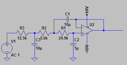
My plan was to make the 1st (passive) stage with a much lower Zout so the loading on it is not big (R3 in above diagram being maybe 1k only).
Playing around here
http://sim.okawa-denshi.jp/en/OPstool.phpwith these values
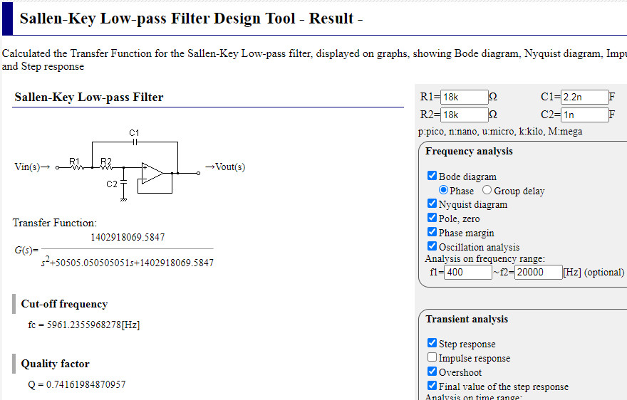
I get 5.3deg phase delay at 400Hz and 6.5deg at 500Hz which is not far off the 5.62deg achievable with a 1 sample DAC table shift, and these are the two frequency limits of main interest.
What I don't have a sim for is a) the extra RC lowpass stage before this and b) a gain of 2x (but AIUI the 2x gain is simply taken care of by making C1 half the value and that keeps the curves the same).


