Author Topic: suggestions for high-resolution tiltmeter (inclinometer) sensor?  (Read 53225 times)

0 Members and 1 Guest are viewing this topic.

Offline branadic

  • Super Contributor
  • ***
  • Posts: 2392
  • Country: de
  • Sounds like noise
Re: suggestions for high-resolution tiltmeter (inclinometer) sensor?
« Reply #300 on: August 20, 2021, 12:15:26 pm »
Seismic activity never has been a problem in the last 14 years. The only real pita however was when they've started to build ZAQuant next to us, scratching on the rocks in the building pit.

-branadic-
Computers exist to solve problems that we wouldn't have without them. AI exists to answer questions, we wouldn't ask without it.
 

Offline ballen

  • Regular Contributor
  • *
  • Posts: 82
  • Country: de
Re: suggestions for high-resolution tiltmeter (inclinometer) sensor?
« Reply #301 on: August 20, 2021, 11:40:00 pm »
I put together the first crude model this evening, following the NASA document. Photo attached below. It works exactly as advertised.  A few notes:

(1) Since I didn't have a CA3039, I used a CA3127 NPN transistor array with bases tied to collectors
(2) I soldered directly to the copper tape on the glass vial
(3) To shift the output to be roughly zero at the center, I inserted a 2pf trim
      capacitor.  This was about 1/3 of full range!
(4) I'm driving it with a 10Vpp sinewave at 300kHz
(5) The full range of bubble motion under the top electrodes is +-16mm, which generates approximately +-500mV,
      corresponding to +-24 arcsec.  So the gain is approximately 20mV/arcsec. I have not measured
      or characterized the noise or stability.

Because my vial is much longer than the NASA one,  I think it makes sense to shift the top electrodes.  I will keep them the same length as currently, but move them towards the ends of the vial so that they just overlap the bubble by (say) 2mm, when the bubble is in the central position.  This should give me a broader monotonic range of capacitance versus motion, though will reduce the gain (mV/arcsec) by about a factor of two.  Will try that tomorrow.
« Last Edit: August 21, 2021, 12:03:39 am by ballen »
 

Offline rhb

  • Super Contributor
  • ***
  • Posts: 3483
  • Country: us
Re: suggestions for high-resolution tiltmeter (inclinometer) sensor?
« Reply #302 on: August 22, 2021, 04:31:56 pm »
Congratulations!  Sorry, I didn't visit for a few days.

The music wire flexure is an alternative to a mechanical pivot.  There are various refinements to such a suspension and it may be TalyVel are using one of those to constrain motion to a  plane.  No matter, the principle is the same. I'm simply proposing to do X & Y, rather than just X.

The purpose of the bumpers is to *prevent* damage by restraining the motion of the plumb bob.  In particular, kinking the music wire.  As for precision, the plumb bob doesn't really matter beyond basic accuracy.  Everything is calibrated by reversal.

I don't know about the physical construction of the diode arrays. Your solution works.  I do know that the large diode and transistor arrays of the past are highly sought after today.  Smaller arrays are still made.

Have Fun!
Reg
 
The following users thanked this post: ballen

Offline ballen

  • Regular Contributor
  • *
  • Posts: 82
  • Country: de
Re: suggestions for high-resolution tiltmeter (inclinometer) sensor?
« Reply #303 on: August 23, 2021, 09:54:29 am »
I'm setting up some logging stuff to compare the Talyvel and the NASA tiltmeter outputs over a few days.

I thought that the following might be of interest.  For anyone who wants to understand how the circuit works, read this article:
https://aip.scitation.org/doi/abs/10.1063/1.1685975

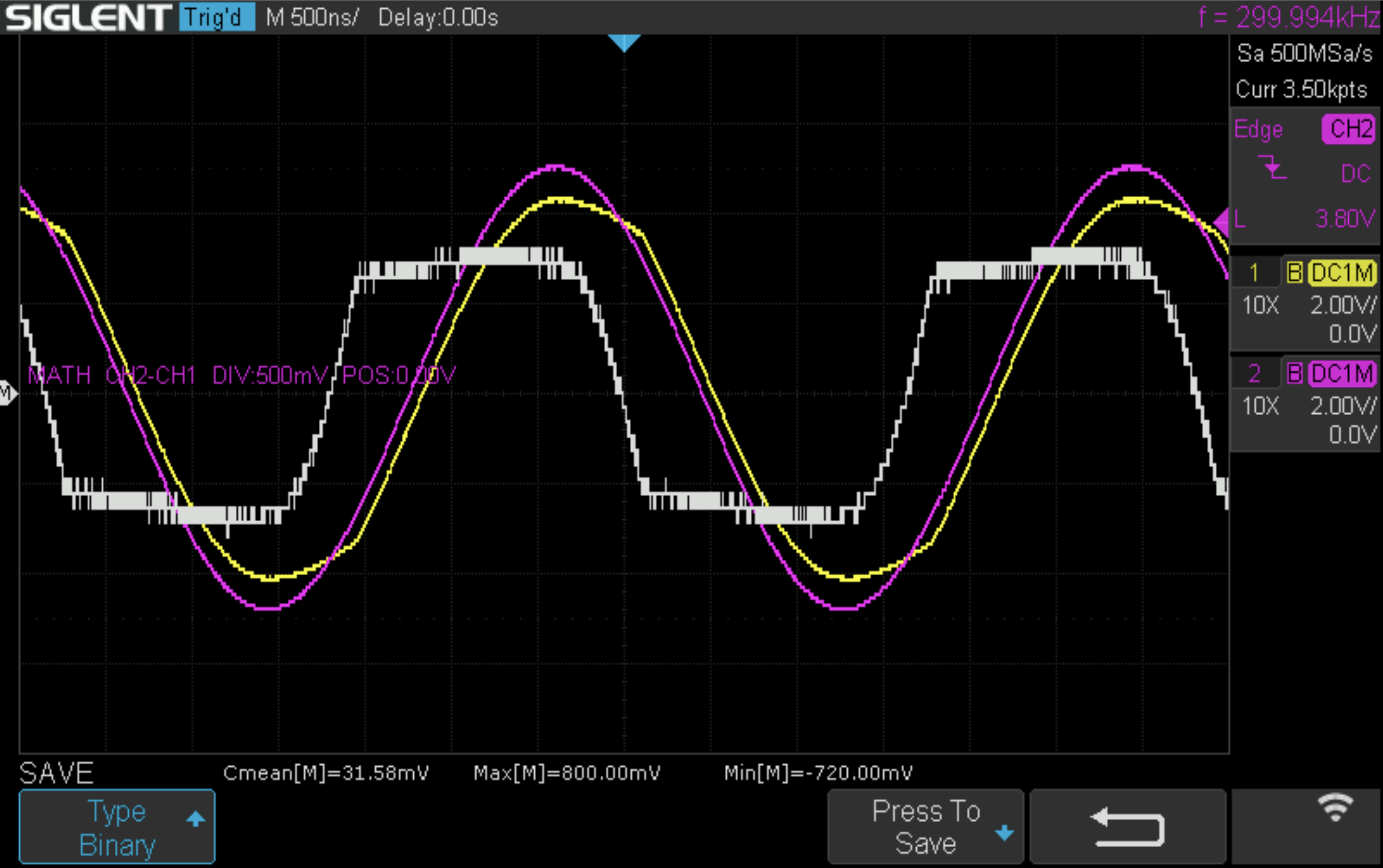
Here is a screenshot showing the behavior:
The pink line is the voltage at the top junction of the bridge, relative to ground.  This is just the oscillator, 10Vpp.
The yellow line shows the voltage at the sense capacitor which is charged by the oscillator when the oscillator is positive.  The white curve is the (magnified) difference between these, which is the voltage across the diode that charges this sense capacitor.  A positive voltage means that the diode is conducting (forward biased).

Start from the second crossing of the pink and yellow curves.   At this point there is no current flow through the diode.  As the oscillator voltage continues to rise, the diode begins to conduct, and the voltage on the capacitor rises, following behind the oscillator.   Eventually the diode swings into full conduction, and charges the capacitor, with about an 800mV drop.   After the oscillator peaks, the voltage on the capacitor would remain fairly stable, but then is discharged by the second diode.  The article shows that if diode drops are neglected, then in the steady state the two capacitors end up with the same average amount of charge, so that (Vp + Vdc) C1 = (Vp - Vdc) C2, where Vp = 5V, Vdc is the output DC voltage of the circuit, and C1 and C2 are the capacitances of the two sense electrodes.   Hence Vdc = (C2 - C1)Vp/(C1+C2).  Here the value of C2-C1 can get to about 10% of C1+C2.   
« Last Edit: August 23, 2021, 10:01:50 am by ballen »
 

Offline RoGeorge

  • Super Contributor
  • ***
  • Posts: 6231
  • Country: ro
Re: suggestions for high-resolution tiltmeter (inclinometer) sensor?
« Reply #304 on: August 23, 2021, 10:11:24 am »
I thought that the following might be of interest.  For anyone who wants to understand how the circuit works, read this article:
https://aip.scitation.org/doi/abs/10.1063/1.1685975

That's the same link posted two pages ago   :)
https://www.eevblog.com/forum/projects/suggestions-for-high-resolution-tiltmeter-(inclinometer)-sensor/msg2417991/#msg2417991

Offline ballen

  • Regular Contributor
  • *
  • Posts: 82
  • Country: de
Re: suggestions for high-resolution tiltmeter (inclinometer) sensor?
« Reply #305 on: August 23, 2021, 04:39:54 pm »
That's the same link posted two pages ago   :)

Yes, I know. There were also many other links posted in that part of the thread, but IMO this reference has the clearest and most direct analysis.  So I thought it would be helpful to put it alongside the waveforms.

I have a practical question for the experts:

The CA3127 is a 16-pin DIP containing five NPN transistors.  The data sheet has the following comment: "The collector of each transistor of the CA3127 is isolated from the substrate by an integral diode. The substrate (Terminal 5) must be connected to the most negative point in the external circuit to maintain isolation between transistors and to provide for normal transistor action."

Currently pin 5 is floating.  However I don't know how to "pull it negative".  Can someone tell me how I could do this?  The largest achievable potential differences in my circuit are 10V, because I have a 10vpp oscillator driving it.   Does this mean that I should take an independent 12V voltage source (or would 7v be enough?) and tie the positive terminal to the "ground" of the circuit and the negative terminal to pin 5?   Will this back-bias all of the transistors?  Is there any way to accomplish this without a separate voltage source?  I've also attached a snapshot of the circuit diagram from the NASA publication.


Here is a link to the datasheet: https://www.digchip.com/datasheets/parts/datasheet/235/CA3127-pdf.php
The comment in question is Note 1 on page 5-2.
« Last Edit: August 23, 2021, 04:47:34 pm by ballen »
 

Online Kleinstein

  • Super Contributor
  • ***
  • Posts: 14246
  • Country: de
Re: suggestions for high-resolution tiltmeter (inclinometer) sensor?
« Reply #306 on: August 23, 2021, 06:44:53 pm »
The transistor array would add extra parasitic capacitance.  I don't think all 4 diodes need to be matched. It should be enough if the upper and lower 2 diodes are matched. So one could use 2  pieces of  SOT23 dual diodes (2 in series each). These are much easier to get and with 2 parts from the same batch the matching may not be so bad. There is little power and thus also need for tight thermal coupling.
 

Offline IDEngineer

  • Super Contributor
  • ***
  • Posts: 1926
  • Country: us
Re: suggestions for high-resolution tiltmeter (inclinometer) sensor?
« Reply #307 on: August 23, 2021, 07:13:48 pm »
For anyone who wants to understand how the circuit works, read this article: https://aip.scitation.org/doi/abs/10.1063/1.1685975
I'd seriously love to read it but it just brings up a summary, and an offer to download a PDF which requires a subscription. Anyone have the actual document?
 

Offline RoGeorge

  • Super Contributor
  • ***
  • Posts: 6231
  • Country: ro
Re: suggestions for high-resolution tiltmeter (inclinometer) sensor?
« Reply #308 on: August 23, 2021, 09:08:30 pm »
Go to Sci-hub and search for the DOI:  10.1063/1.1685975, or simply paste the link in the search box.
https://sci-hub.st/https://aip.scitation.org/doi/abs/10.1063/1.1685975
 
The following users thanked this post: oilburner

Offline ballen

  • Regular Contributor
  • *
  • Posts: 82
  • Country: de
Re: suggestions for high-resolution tiltmeter (inclinometer) sensor?
« Reply #309 on: August 23, 2021, 10:56:50 pm »
The transistor array would add extra parasitic capacitance. 
I don't think all 4 diodes need to be matched. It should be enough if the upper and lower 2 diodes are matched. So one could use 2  pieces of  SOT23 dual diodes (2 in series each). These are much easier to get and with 2 parts from the same batch the matching may not be so bad. There is little power and thus also need for tight thermal coupling.

The Harrison and Dimeff paper says "At or near the balance condition, the calculated contribution of the diodes to the dc output voltage is
\Delta V = 1/2 ((V_d1-V_d2) - (V_d3 - V_d4))
which suggests the need for temperature tracking at least by pairs and preferably by all four diodes. In the experimental tests the circuit includes a commercially available diode-quad assembly with a temperature tracking specification of \Delta V_d <5.0 mV for -55°C< T<l00°C."


Here \Delta V is the change in the DC output level due to a change in the diode forward voltage drops, V_d1 and V_d2 are the forward drop diode voltages in the upper half of the circuit, and V_d3 and V_d4 are the same in the lower half.

So as you say, it's enough to ensure that diodes 1 and 2 track each other, and that diodes 3 and 4, track each other in forward voltage drops as the ambient temperature changes.  Note also that there is virtually no power dissipation in this circuit, so the diode temperature is primarily tracking the changing ambient temp. 
« Last Edit: August 23, 2021, 11:01:04 pm by ballen »
 
The following users thanked this post: oilburner

Offline rhb

  • Super Contributor
  • ***
  • Posts: 3483
  • Country: us
Re: suggestions for high-resolution tiltmeter (inclinometer) sensor?
« Reply #310 on: August 24, 2021, 01:00:12 am »
You can ameliorate the lack of monolithic arrays by mounting tempco selected devices to a common heatsink and then holding the temperature as stable as possible.  You can also fix that and many other shortcomings in post-processing.

What is the use case?  Geophysics or engineering?  I'm familiar with both.

In the non-TalyVel pendulum sensor department, consider a 0.003" music wire flexure with a turned cylinder suspended from it with HDPE stops to prevent excessive displacement.  With 3 silicon carbide ball feet and 3 adjustable capacitor plates, a measuring system can be set up which will resolve very small angles. Initial setup is by rotation through all 3 positions on a well leveled surface plate to place the capacitor plates in the proper locations relative to the pendulum..  After that, calibration is by reversal in the field on an almost level surface.

An equilateral triangle template that ensured all 3 measurements had the balls consistently placed would be all one needed for calibration.  But that's not geophysical observational kit.  The vials are better for that with good quality vials.

It just occurred to me that a simple fixture which would take a vial and then automatically test it for accuracy is actually not all that hard.  A 3D printed plastic mount with a pair of copper foil strips on the vial contact surface would do.  Then you just need a very small angular adjustment mechanism and data acquisition.

Have Fun!
Reg
 

Offline ballen

  • Regular Contributor
  • *
  • Posts: 82
  • Country: de
Re: suggestions for high-resolution tiltmeter (inclinometer) sensor?
« Reply #311 on: August 24, 2021, 08:26:03 am »
So one could use 2  pieces of  SOT23 dual diodes (2 in series each). These are much easier to get and with 2 parts from the same batch the matching may not be so bad.

Could you suggest a specific part or parts to me?  Most important is that (1) at fixed current, the difference in forward offset voltage is a constant function of temperature and (2) that the difference in reverse bias capacitance is a constant function of temperature.
 

Offline ballen

  • Regular Contributor
  • *
  • Posts: 82
  • Country: de
Re: suggestions for high-resolution tiltmeter (inclinometer) sensor?
« Reply #312 on: August 24, 2021, 09:53:59 am »
You can ameliorate the lack of monolithic arrays by mounting tempco selected devices to a common heatsink and then holding the temperature as stable as possible. You can also fix that and many other shortcomings in post-processing. What is the use case?  Geophysics or engineering?

Agreed that temperature dependence can be removed in postprocessing, but would prefer to minimize it at the source as much as possible.

I'm mainly interested in surface plate mapping.  So bandwidth from DC to 0.5 Hz would be fine.

Quote
Consider a 0.003" music wire flexure with a turned cylinder suspended from it with HDPE stops to prevent excessive displacement.

I am going to concentrate on the vials for now, thanks.  Have you computed the rotational period and damping time for the configuration that you suggest?  In my applications I need to move the sensor every few seconds. So I need something that damps down in a couple of seconds.

Quote
It just occurred to me that a simple fixture which would take a vial and then automatically test it for accuracy is actually not all that hard.  A 3D printed plastic mount with a pair of copper foil strips on the vial contact surface would do.  Then you just need a very small angular adjustment mechanism and data acquisition.

That's very close to what I have already.  My vials were delivered in a 3d printed case, and if you look at my earlier photo, you'll see that I'm using that as a mount, for the moment.  It's adequate for testing purposes.

Cheers,
   Bruce
 

Online Kleinstein

  • Super Contributor
  • ***
  • Posts: 14246
  • Country: de
Re: suggestions for high-resolution tiltmeter (inclinometer) sensor?
« Reply #313 on: August 24, 2021, 11:44:49 am »
So one could use 2  pieces of  SOT23 dual diodes (2 in series each). These are much easier to get and with 2 parts from the same batch the matching may not be so bad.

Could you suggest a specific part or parts to me?  Most important is that (1) at fixed current, the difference in forward offset voltage is a constant function of temperature and (2) that the difference in reverse bias capacitance is a constant function of temperature.

The specs usually don't specify the matching, but usually it is quite good. The temperature dependence is usually proportional to 1.12 V - V_f.  Voltage matching also implies TC matching. The parameters to look for are more low capacitance, not too much leakage and no too much Trr (e.g. < 200 ns) .
The obvious candidate would be BAV99 in the version with series connection.
 

Offline ballen

  • Regular Contributor
  • *
  • Posts: 82
  • Country: de
Re: suggestions for high-resolution tiltmeter (inclinometer) sensor?
« Reply #314 on: August 24, 2021, 11:55:57 am »
The obvious candidate would be BAV99 in the version with series connection.

I just ordered 30, cost was 2.90 Euros, including shipping.
 

Offline rhb

  • Super Contributor
  • ***
  • Posts: 3483
  • Country: us
Re: suggestions for high-resolution tiltmeter (inclinometer) sensor?
« Reply #315 on: August 24, 2021, 08:01:51 pm »
LoL!

Aside from geophysical monitoring, surface plate mapping is my other application of interest.

I assumed that the pendulum properties would be determined during construction.  I think once per second is rather optimistic.  Bubbles don't settle quickly.

I happened to come across the bag of diode arrays a few days ago, so I may build the basic NASA circuit using the crappy Chinese vials.

I just realized that my HP 4284A reads to 0.01 femtoFarads.  Now to find something that will hold the vial safely.

Have Fun!
Reg
 

Offline ballen

  • Regular Contributor
  • *
  • Posts: 82
  • Country: de
Re: suggestions for high-resolution tiltmeter (inclinometer) sensor?
« Reply #316 on: December 22, 2022, 07:23:07 am »
The best of those Rieker devices have a resolution/accuracy of about 0.05 = 1/20 degree. In this thread, we are talking about inclinometers that can measure and resolve 0.1 arcseconds.  That is 1/(60 x 60 x 10) = 0.000028 degree.  In other words, the most sensitive of the devices made by Rieker miss the target by more than a factor of a thousand.
 

Offline babysitter

  • Frequent Contributor
  • **
  • Posts: 893
  • Country: de
  • pushing silicon at work
Re: suggestions for high-resolution tiltmeter (inclinometer) sensor?
« Reply #317 on: December 24, 2022, 04:56:35 pm »
Yes, I just have to give it a try.
I'm not a feature, I'm a bug! ARC DG3HDA
 

Offline Martinn

  • Frequent Contributor
  • **
  • Posts: 299
  • Country: ch
Re: suggestions for high-resolution tiltmeter (inclinometer) sensor?
« Reply #318 on: December 29, 2022, 08:13:08 pm »
On a mechanics forum a while ago there was a discussion on how to build a Wyler Niveltronic like tilt meter.
My thought was: Could a 1 um/m tilt meter be built using a off the shelf signal processing frontend? Without any analog tinkering at all?
The idea was to build a magnetically damped pendulum and replace the LVDT by a capacitive sensor. Assuming 15 mm sensor diameter and 100 um nominal air gap, this gives a capacity of around 15 pF. For an effective pendulum length of 40 mm, 1 um/m tilt translates into 40 nm sensor change. 100 um/40 nm= 2500, so a 12 bit resolution seems sufficient.

Searching for usable frontends resulted in the PCap04 - all other capacitive sensor interfaces seem to require floating sensors, while I wanted the pendulum to be grounded. Working with the PCap04 proved to be a nightmare - I found the documentation truly miserable and working with this chip it lots of guesswork, trial and error and reverse engineering of the eval kit operation (and some code snippets floating around).
Initially I had a more complex sensor arrangement in mind, but decided to simply put the pad on a PCB. Whether this can be made accurate to 40 nm remains to be seen. The PCB is mounted to the frame via a magnetic kinematic mount (three balls, six cylinders), providing at least in theory a precisely constrained mount without adding any torque onto the PCB (which certainly would result in creep of the FR-4). The kinematic mount consists of six dowel pins that are glued into slots on the PCB and three balls on the tip of micrometer heads. To aid achieving an even 100 um air gap, three auxiliary sensors are placed around the center sensor.

Currently I have a simplified setup where I can set a fixed position via a reference plate. After much trial and error the PCap04 gives useable results and I am achieving an RMS error of less (not much) than 40 nm, with lots of drift (which I assume is thermal and is no wonder given my setup). So for now it seems to work and I am waiting for the completed pendulum assembly.

For calibration the idea is to put the device on a precision granite beam and support it using gauge blocks. This way I should be able to set the tilt in increments of 10 um/m. If linearity with this is OK and noise good enough, I think it should achive 1 um/m, although I have no direct means of verifying that. Drift will be interesting... to be seen.
The final test will be trying to measure the topology of a surface plate and comparing it to its calibration certificate. This will also define the required drift stability - I'd assume this can be done in 15 minutes so this is the time frame for stability. For machine leveling required accuracy will be lower.

As I said this is kind of a fun project. I have nothing in my workshop requiring (even remotely) that precision - my lathe sits on rubber bumpers. It's really to find out how far you can push an off the shelf frontend without diving into analog design.

- Martin
 
The following users thanked this post: JBeale, oilburner, jpanhalt

Offline Martinn

  • Frequent Contributor
  • **
  • Posts: 299
  • Country: ch
Re: suggestions for high-resolution tiltmeter (inclinometer) sensor?
« Reply #319 on: October 14, 2023, 11:53:28 am »
Short update. Mechanics arrived (friend of mine did these, precision scraped functional surfaces) and so far looks good. RMS noise of the sensor is below the required 1 um/m, although not by a huge margin.
Next step will be to build a test jig that can tilt the assembly by defined amounts. Easiest would be just to put a bunch of 50 nm shims below one side (just kidding).
Current plan is to use two precision ground plates and tilt them using a differential micrometer in addition to a piezo stack. Of course this will not give me precise reference angles, but for this I'd have to invest in metrology grade ($$$) reference instruments like an interferometer and a climate controlled lab on its own foundation.
 

Offline RoGeorge

  • Super Contributor
  • ***
  • Posts: 6231
  • Country: ro
Re: suggestions for high-resolution tiltmeter (inclinometer) sensor?
« Reply #320 on: October 14, 2023, 01:20:56 pm »
Trying to understand how that works, and couldn't figure what pendulates, and where, and relative to which plane.  Googled 'Wyler Niveltronic' and it only returns marketing pitch flyers with specs and applications.

Do you have any link that describes the basic principles for that method of measuring the tilt, please?

Offline Martinn

  • Frequent Contributor
  • **
  • Posts: 299
  • Country: ch
Re: suggestions for high-resolution tiltmeter (inclinometer) sensor?
« Reply #321 on: October 14, 2023, 01:41:39 pm »
Wyler Niveltronic (AFAIK) uses a pendulum where tilt is measured using a LVDT. Can't find an inside image right now. Obviously their LVDT signal conditioning is low noise and stable enough, a hassle I wanted to avoid using a capacitive distance sensor.

See the annotated image on my sensor. It's really just a pendulum with the sensor PCB besides it. Air gap is only 100 um so you don't see it in the picture.
 
The following users thanked this post: mycroft, RoGeorge

Offline PCB.Wiz

  • Super Contributor
  • ***
  • Posts: 1561
  • Country: au
Re: suggestions for high-resolution tiltmeter (inclinometer) sensor?
« Reply #322 on: October 14, 2023, 09:01:56 pm »
Voltage matching also implies TC matching. The parameters to look for are more low capacitance, not too much leakage and no too much Trr (e.g. < 200 ns) .
The obvious candidate would be BAV99 in the version with series connection.

Pulling this forward to 2023, there are 4-diode versions of BAV199, BAV99 etc in 6 pin SOT363 &  SOT26 packages, which allow this to be done in one package.

That give you two choices on wiring.
I'm guessing left-right matching matters more than up-down matching, so the pairs would be used left-right.
« Last Edit: October 14, 2023, 09:17:06 pm by PCB.Wiz »
 

Offline Martinn

  • Frequent Contributor
  • **
  • Posts: 299
  • Country: ch
Re: suggestions for high-resolution tiltmeter (inclinometer) sensor?
« Reply #323 on: November 29, 2023, 05:55:20 pm »
One more update. 50 nm shims proved to be unobtainium, instead I got a differential adjuster head. 25 um per revolution, 1 um/500 nm divisions. Mounted this in a plate together with two conventional micrometer heads. Most difficult in this was to buy the precision machined plates here in Switzerland and to cut the 1/4-80 fine thread for the DM22 adjuster.

Setup is still not optimal, it should be on a half ton granite slab in the basement instead of sitting on my wobbly wooden desk. But together with the adjuster graduation, one gets a very good idea on short term stability and noise.
A 1 um step on the adjuster gives an angle of (170 mm baseline) 1.2 arcseconds, which is 6 times higher than the target 1 um/m 0.21 arcseconds.

In the graph, you can see three steps: First two 1 um and then one 500 nm adjuster step. Noise judged visually is around 100 nm p-p. The PCAP04 is set to 2 samples/s, so with a 10x averaging (5 s settling time) one could reduce this further. BTW the ratio between adjuster step and actual distance at the pendulum is 170/40 mm, so the 100 nm p-p noise is actually 24 nm at the PCB. Not too shabby, I'd say. How much of this is coming from the PCAP04 and how much is air turbulence or vibration of the building remains to be seen. I need to finish the display module so I can close the housing and put this on a concrete basement floor.
« Last Edit: November 29, 2023, 05:57:20 pm by Martinn »
 

Offline jmelson

  • Super Contributor
  • ***
  • Posts: 2766
  • Country: us
Re: suggestions for high-resolution tiltmeter (inclinometer) sensor?
« Reply #324 on: November 29, 2023, 08:06:36 pm »
I'm a little late chiming in here, but...  I have a Taylor Hobson Talyvel electronic level.  From the spec sheet it can reliably read 0.1 arc second.  Mine has been around a bit, so maybe is still good to 0.2 arc second or so.  The sensing head is about a 3" block, with maybe a 5" wide base.  If you stick one human hair under one end, it goes off-scale.  The sensing mechanism is pendulum suspended by 5 TINY thinner than a hair wires.  It hangs between two inductive sensors that are wired into some kind of AC bridge.  Damping is provided by a magnet that acts on an aluminum plate at the side of the pendulum.  When unlocked, the pendulum is only free to swing maybe 1-2 mm between the sensors.
Jon


Share me

Digg  Facebook  SlashDot  Delicious  Technorati  Twitter  Google  Yahoo
Smf