Author Topic: The Rössler attractor challenge.  (Read 62460 times)

0 Members and 1 Guest are viewing this topic.

Offline GKTopic starter

  • Super Contributor
  • ***
  • Posts: 2607
  • Country: au
The Rössler attractor challenge.
« on: September 03, 2013, 01:26:53 pm »
Depending on the enthusiasm and interest of others out there, this thread may either flop or become a catalyst for a veritable flurry of highly exciting activity.

The challenge is to design and breadboard an functioning analog circuit to solve the three coupled differential equations of the Rössler attractor:


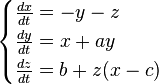
Those equations are taken from the Wikipedia page here: http://en.wikipedia.org/wiki/R%C3%B6ssler_attractor

The constants, a, b and c are subject to some variability, but a good place to start is a=0.2, b=0.2 and c=5.7.
The variables can be altered so long as the values chosen still result in a chaotic solution.

Now, being the amazingly clever person that I am, I have already worked out a circuit to do the job. Here it is:


At this stage I won't post the circuit diagram, as that would give most of the game away. However I will reveal that I simplified the initial solution down to six op-amp stages (one quad and one dual package) and one analog multiplier chip. Here is the resultant display:


Ultimately, it would be interesting to see how multiple independent workings of the design problem converge on the same outcome. So, at this stage, here is what I suggest for all those who may wish to take part:

1) Work out and breadboard your circuit
2) Post a photo of the resultant oscilloscope display and give your values for a, b and c.
3) Give your active device count (op-amps, etc) but do not reveal your circuit details or workings.

Only once enough players of the game have posted up their scope display photos as proofs off accomplishment can the circuits and workings be revealed. He or she who solves the problem with the simplest circuit wins!

However, you must build your circuit and demonstrate success with an oscilloscope display photo at a minimum!. SPICE results are not acceptable! There are minor challenges to getting a real life analogue solution up and running that to not present themselves in virtual reality; namely, I can reveal, the issue of scaling so that the solution falls withing the voltage swinging limits of the active circuitry and dealing with offset voltages.

Finally, on the topic of the scope display, unless you have a 3-dimensional projection unit like I have, you will need to build a simple circuit to give the Rössler Attractor, which is a 3 dimensional object represented by three-axes variables, perspective for a 2 axis XY oscilloscope display. Attached immediately below is the simple circuit required. It adds the X and Z solutions/signals in such a way as to give a 45 degree tilt to the projection along the horizontal axis, as shown. You do not have to build this circuit to demonstrate success of course, but your display of the attractor will not be as pretty as it may be otherwise as you will be restricted to viewing/displaying the attractor "end on" only, with a display generated by a selection of only two of the three axis variables at a time.     


Have fun!
« Last Edit: September 03, 2013, 01:44:10 pm by GK »
Bzzzzt. No longer care, over this forum shit.........ZZzzzzzzzzzzzzzzz
 

Offline kfitch42

  • Frequent Contributor
  • **
  • Posts: 300
  • Country: us
Re: The Rössler attractor challenge.
« Reply #1 on: September 03, 2013, 05:06:51 pm »
Speaking of Chaotic electronics, have you ever tried Chua's Circuit? http://en.wikipedia.org/wiki/Chua%27s_circuit

That one has been on my todo list for a while... but given the fact that the inbound flux of my todo list is greater than the outbound flux... and the honeydo list having higher priority...
 

Offline Dajgoro

  • Frequent Contributor
  • **
  • Posts: 322
  • Country: hr
    • hackaday.io
Re: The Rössler attractor challenge.
« Reply #2 on: September 03, 2013, 07:03:16 pm »
Could somebody explain what do exactly do this circuits do, and is there any propose for them?
 

Offline Paul Price

  • Super Contributor
  • ***
  • Posts: 1419
Re: The Rössler attractor challenge.
« Reply #3 on: September 04, 2013, 12:58:02 am »
Rossler attractor equations are useful in modeling equilibrium in chemical reactions.
 

Offline GKTopic starter

  • Super Contributor
  • ***
  • Posts: 2607
  • Country: au
Re: The Rössler attractor challenge.
« Reply #4 on: September 04, 2013, 08:49:32 am »
Speaking of Chaotic electronics, have you ever tried Chua's Circuit? http://en.wikipedia.org/wiki/Chua%27s_circuit

Yep

Could somebody explain what do exactly do this circuits do, and is there any propose for them?

Purdy squiggles on the oscilloscope.
Bzzzzt. No longer care, over this forum shit.........ZZzzzzzzzzzzzzzzz
 

Offline johnwa

  • Frequent Contributor
  • **
  • Posts: 255
  • Country: au
    • loopgain.net - a few of my projects
Re: The Rössler attractor challenge.
« Reply #5 on: September 04, 2013, 12:29:40 pm »
Well, I have managed to produce some pretty squiggles, though unfortunately I don't think they are the ones we are looking for. There is obviously a bit of clipping going on somewhere, I am not sure if this is anything to do with it.

My circuit sounds fairly similar to yours GK, six op-amps and an AD633.

I guess I will keep working at it, though I probably won't have any time before the weekend. Any thoughts on debugging a circuit like this? I couldn't get my simulation to run at all  :(.
 

Offline GKTopic starter

  • Super Contributor
  • ***
  • Posts: 2607
  • Country: au
Re: The Rössler attractor challenge.
« Reply #6 on: September 04, 2013, 12:59:37 pm »
Nice!  :D

It took me two late evenings to get mine to work, and there was little success on the first night. For getting it to simulate, you often need to introduce a transient of some sort to get things kick started. When simulating stubborn oscillators in LTspice, I often use an ideal current source configured as a pulse generator to inject a brief, small amplitude current pulse into the loop right at the beginning (only) of the simulation. A VCVS configured as a "one shot" pulse generator can also be used, with a series resistor (high value, say 1M to 10M) to inject a "start up" transient current pulse into an op-amp virtual earth node/summing junction or similar.

It does look like you have some clipping there, so the scaling may have to be looked at a little closer. Also your b constant is perhaps too far out of range (hint: consider the contribution of the input/output offset error voltages of the multiplier).
 
« Last Edit: September 04, 2013, 01:01:38 pm by GK »
Bzzzzt. No longer care, over this forum shit.........ZZzzzzzzzzzzzzzzz
 

Offline johnwa

  • Frequent Contributor
  • **
  • Posts: 255
  • Country: au
    • loopgain.net - a few of my projects
Re: The Rössler attractor challenge.
« Reply #7 on: September 04, 2013, 01:07:35 pm »
Well, by the highly technical process of connecting up a capacitance substitution box and twiddling the knobs at random, it appears that we now have chaos! Though don't ask me what the coefficients are now  :).

On another note, after further research, it appears that it may be possible to reduce the op-amp count. (I found a simple circuit for a different system of DEs, I will post a link later, so as not to spoil the challenge)
 

Offline GKTopic starter

  • Super Contributor
  • ***
  • Posts: 2607
  • Country: au
Re: The Rössler attractor challenge.
« Reply #8 on: September 04, 2013, 01:12:38 pm »
Great! - besides the clipping issue you've got it.
Bzzzzt. No longer care, over this forum shit.........ZZzzzzzzzzzzzzzzz
 

Offline GKTopic starter

  • Super Contributor
  • ***
  • Posts: 2607
  • Country: au
Re: The Rössler attractor challenge.
« Reply #9 on: September 06, 2013, 09:11:58 am »
On another note, after further research, it appears that it may be possible to reduce the op-amp count. (I found a simple circuit for a different system of DEs, I will post a link later, so as not to spoil the challenge)


That would definitely be interesting. Unfortunately this thread hasn't been that much of a hit so far! I think I give it another couple of evenings before posting my circuit and SPICE files if there remains to be no further participation.
Bzzzzt. No longer care, over this forum shit.........ZZzzzzzzzzzzzzzzz
 

Offline Crazy Ape

  • Regular Contributor
  • *
  • Posts: 181
Re: The Rössler attractor challenge.
« Reply #10 on: September 06, 2013, 09:31:41 am »
Looks like fun, I might give a digital version a go, though other stuff eats all my time at the moment so it won't be for a while.
http://www.eecs.berkeley.edu/~chua/papers/Eguchi99.pdf

More here:
http://iaesjournal.com/online/index.php/TELKOMNIKA/article/download/2503/pdf
« Last Edit: September 06, 2013, 09:41:06 am by Crazy Ape »
 

Offline HackedFridgeMagnet

  • Super Contributor
  • ***
  • Posts: 2028
  • Country: au
Re: The Rössler attractor challenge.
« Reply #11 on: September 06, 2013, 09:36:24 am »
I would love to try but haven't the time. But don't think your thread is not interesting to others.
 

Offline mikeselectricstuff

  • Super Contributor
  • ***
  • Posts: 13748
  • Country: gb
    • Mike's Electric Stuff
Re: The Rössler attractor challenge.
« Reply #12 on: September 06, 2013, 09:55:22 am »
Might be interesting to make these produce chaotic audio patterns
Youtube channel:Taking wierd stuff apart. Very apart.
Mike's Electric Stuff: High voltage, vintage electronics etc.
Day Job: Mostly LEDs
 

Offline EEVblog

  • Administrator
  • *****
  • Posts: 37740
  • Country: au
    • EEVblog
Re: The Rössler attractor challenge.
« Reply #13 on: September 06, 2013, 09:58:32 am »
I want to have a crack at this, but I suspect it'll take a good day of playing at least. Will have to wait until after the Electronex show.
 

Offline GKTopic starter

  • Super Contributor
  • ***
  • Posts: 2607
  • Country: au
Re: The Rössler attractor challenge.
« Reply #14 on: September 06, 2013, 01:01:42 pm »
Whoa there! I'll hold off on posting any circuit details for a while then!
Bzzzzt. No longer care, over this forum shit.........ZZzzzzzzzzzzzzzzz
 

Offline johnwa

  • Frequent Contributor
  • **
  • Posts: 255
  • Country: au
    • loopgain.net - a few of my projects
Re: The Rössler attractor challenge.
« Reply #15 on: September 07, 2013, 02:24:54 pm »
Well, I think I have got it down to four op-amps and a multiplier now (after getting some inspiration from the circuit I mentioned previously). Subjectively, it does not seem quite as chaotic as the old circuit, but it still gives quite a good display on the CRO. The clipping is gone too.

Again, I started off calculating the component values to suit the supplied parameters, but I ended up a fair way off these values for best results. I made all the parameters adjustable, and it took a fair bit of 'hill-climbing' to optimise the performance.

I haven't gone too far into calculation of the offset voltages, etc - I just assumed ideal behaviour, and chose the impedances low enough to swamp out the bias currents, but high enough not to cause problems with the op-amps' drive capabilities. Possibly these values could be optimised further. I will post a schematic once everyone else has had a go.


Offline Dajgoro

  • Frequent Contributor
  • **
  • Posts: 322
  • Country: hr
    • hackaday.io
Re: The Rössler attractor challenge.
« Reply #16 on: September 08, 2013, 01:09:54 am »
I just remembered that last year I've made a kinda odd experimental circuit with 4000 series logic which included lots of phase shifting interlocked oscillators. I made that as a university project, and it is supposed to be a true random generator implemented as a CMOS IC. The spice simulation of the topology and the 4000 series prototype both gave similar results, so it works. But I've never thought about what would happen if I were to hook the thing to the scope in XY mode. So I now tried it, and the output would just generate a solid green block, but when probing some of the oscillators that are in some way connected I get some very unique squiggles.  ;D

Not really the Rössler attractor, but looks weird, so wanted to post some of the many squiggles.

Sorry for my offtopic post.
 

Offline smashedProton

  • Frequent Contributor
  • **
  • Posts: 641
  • Country: us
Re: The Rössler attractor challenge.
« Reply #17 on: September 08, 2013, 04:14:16 am »
I am going to try this out when I get back to the lab.   This is probably way outside of my skill level though..
http://www.garrettbaldwin.com/

Invention, my dear friends, is 93% perspiration, 6% electricity, 4% evaporation, and 2% butterscotch ripple.
 

Offline GKTopic starter

  • Super Contributor
  • ***
  • Posts: 2607
  • Country: au
Re: The Rössler attractor challenge.
« Reply #18 on: September 08, 2013, 12:20:29 pm »
Well, I think I have got it down to four op-amps and a multiplier now (after getting some inspiration from the circuit I mentioned previously). Subjectively, it does not seem quite as chaotic as the old circuit, but it still gives quite a good display on the CRO. The clipping is gone too.


OK, good work!

In case anyone out there has an inclination to experiment with 3-D projections, all the information required to get started is here:


The transformation units described were the basis for my "3D Projection unit":

« Last Edit: September 08, 2013, 12:23:12 pm by GK »
Bzzzzt. No longer care, over this forum shit.........ZZzzzzzzzzzzzzzzz
 

Offline GKTopic starter

  • Super Contributor
  • ***
  • Posts: 2607
  • Country: au
Re: The Rössler attractor challenge.
« Reply #19 on: September 08, 2013, 12:25:26 pm »
I just remembered that last year I've made a kinda odd experimental circuit with 4000 series logic which included lots of phase shifting interlocked oscillators. I made that as a university project, and it is supposed to be a true random generator implemented as a CMOS IC. The spice simulation of the topology and the 4000 series prototype both gave similar results, so it works. But I've never thought about what would happen if I were to hook the thing to the scope in XY mode. So I now tried it, and the output would just generate a solid green block, but when probing some of the oscillators that are in some way connected I get some very unique squiggles.  ;D

Not really the Rössler attractor, but looks weird, so wanted to post some of the many squiggles.

Sorry for my offtopic post.


Does that CRT have a white phosphor, or is that just the way the photos turned out? Never seen a CRO with a white phosphor CRT before.
Bzzzzt. No longer care, over this forum shit.........ZZzzzzzzzzzzzzzzz
 

Offline EEVblog

  • Administrator
  • *****
  • Posts: 37740
  • Country: au
    • EEVblog
Re: The Rössler attractor challenge.
« Reply #20 on: September 08, 2013, 01:30:06 pm »
Does that CRT have a white phosphor, or is that just the way the photos turned out? Never seen a CRO with a white phosphor CRT before.

I remember a short period in the 80's when "paper white" CRT screens were all the rage. None of the green or amber rubbish!
 

Offline mamalala

  • Supporter
  • ****
  • Posts: 777
  • Country: de
Re: The Rössler attractor challenge.
« Reply #21 on: September 08, 2013, 02:56:32 pm »
Does that CRT have a white phosphor, or is that just the way the photos turned out? Never seen a CRO with a white phosphor CRT before.
I remember a short period in the 80's when "paper white" CRT screens were all the rage. None of the green or amber rubbish!


The Atari B/W screens where also black and white, as well as the displays of the first Macintosh computers. A lot of electronic typesetting equipment also used B/W displays.

Greetings,

Chris
 

Offline Dajgoro

  • Frequent Contributor
  • **
  • Posts: 322
  • Country: hr
    • hackaday.io
Re: The Rössler attractor challenge.
« Reply #22 on: September 08, 2013, 04:45:13 pm »
I just remembered that last year I've made a kinda odd experimental circuit with 4000 series logic which included lots of phase shifting interlocked oscillators. I made that as a university project, and it is supposed to be a true random generator implemented as a CMOS IC. The spice simulation of the topology and the 4000 series prototype both gave similar results, so it works. But I've never thought about what would happen if I were to hook the thing to the scope in XY mode. So I now tried it, and the output would just generate a solid green block, but when probing some of the oscillators that are in some way connected I get some very unique squiggles.  ;D

Not really the Rössler attractor, but looks weird, so wanted to post some of the many squiggles.

Sorry for my offtopic post.


Does that CRT have a white phosphor, or is that just the way the photos turned out? Never seen a CRO with a white phosphor CRT before.

No, it is not white at all!
Since I don't have a camera I took the pictures with my cellphone, and since it was in the dark, it auto adjusted the white balance so a perfectly good green color became white...

Edit: The screen surface is white, but the trace is green/cyan.
« Last Edit: September 09, 2013, 12:11:12 am by Dajgoro »
 

Offline GKTopic starter

  • Super Contributor
  • ***
  • Posts: 2607
  • Country: au
Re: The Rössler attractor challenge.
« Reply #23 on: September 09, 2013, 02:01:42 am »
Does that CRT have a white phosphor, or is that just the way the photos turned out? Never seen a CRO with a white phosphor CRT before.

I remember a short period in the 80's when "paper white" CRT screens were all the rage. None of the green or amber rubbish!


Do you mean monitor CRT's or specifically CRO CRT's? I like the blue phosphor of my Tek 551.


Bzzzzt. No longer care, over this forum shit.........ZZzzzzzzzzzzzzzzz
 

Offline notsob

  • Frequent Contributor
  • **
  • Posts: 696
  • Country: au
Re: The Rössler attractor challenge.
« Reply #24 on: September 09, 2013, 02:05:14 am »
I supported TeleVideo equipment for a few years, their ' Paper White ' ascii monitors were very popular when they came out.
« Last Edit: September 09, 2013, 04:08:55 am by notsob »
 

Offline firehopper

  • Frequent Contributor
  • **
  • Posts: 408
  • Country: us
Re: The Rössler attractor challenge.
« Reply #25 on: September 09, 2013, 03:33:44 am »
Does that CRT have a white phosphor, or is that just the way the photos turned out? Never seen a CRO with a white phosphor CRT before.

I remember a short period in the 80's when "paper white" CRT screens were all the rage. None of the green or amber rubbish!


Do you mean monitor CRT's or specifically CRO CRT's? I like the blue phosphor of my Tek 551.

are you sure it was blue, or green with a blue overlay? :)
 

Offline c4757p

  • Super Contributor
  • ***
  • Posts: 7799
  • Country: us
  • adieu
Re: The Rössler attractor challenge.
« Reply #26 on: September 09, 2013, 03:38:05 am »
I'd say it is the blue version.
No longer active here - try the IRC channel if you just can't be without me :)
 

Offline GKTopic starter

  • Super Contributor
  • ***
  • Posts: 2607
  • Country: au
Re: The Rössler attractor challenge.
« Reply #27 on: September 09, 2013, 04:06:41 am »
P11 phosphor, 460nm, to be specific  :)
Bzzzzt. No longer care, over this forum shit.........ZZzzzzzzzzzzzzzzz
 

Offline EEVblog

  • Administrator
  • *****
  • Posts: 37740
  • Country: au
    • EEVblog
Re: The Rössler attractor challenge.
« Reply #28 on: September 09, 2013, 04:07:28 am »
Do you mean monitor CRT's or specifically CRO CRT's? I like the blue phosphor of my Tek 551.

Oops, computer CRT monitors.
 

Offline johnwa

  • Frequent Contributor
  • **
  • Posts: 255
  • Country: au
    • loopgain.net - a few of my projects
Re: The Rössler attractor challenge.
« Reply #29 on: September 10, 2013, 12:05:49 pm »

OK, good work!

In case anyone out there has an inclination to experiment with 3-D projections, all the information required to get started is here:


The transformation units described were the basis for my "3D Projection unit":


I had a look at your analogue computer thread GK, it seems you are an expert in this sort of thing! A very impressive project.

A few thoughts on the 3D projector: You said you had trouble sourcing the sin/cos pots, and had to resort to a digital solution. Did you consider using analogue multipliers driven by sine function generators - I would have thought this would be more in keeping with the 'analogue' nature of the project!

Another idea - with your RGB CRT display, what about building a second projector, slaved to the first, and offset a few degrees. Then feed the red and blue channels, for a stereoscopic display.

For people interested in visualising the Rossler attractor, the 'flow' hack from XScreensaver provides displays of a number of strange attractors. including the Rossler. Unfortunately, there is no way of controlling which system is displayed - they are chosen at random!
 

Offline GKTopic starter

  • Super Contributor
  • ***
  • Posts: 2607
  • Country: au
Re: The Rössler attractor challenge.
« Reply #30 on: September 10, 2013, 01:23:47 pm »
A few thoughts on the 3D projector: You said you had trouble sourcing the sin/cos pots, and had to resort to a digital solution. Did you consider using analogue multipliers driven by sine function generators - I would have thought this would be more in keeping with the 'analogue' nature of the project!


Yes, I did! I considered a pair of simplified/scaled-down versions of my sin/cos function module ( https://www.eevblog.com/forum/projects/home-brew-analog-computer-system/msg192626/#msg192626 )  to generate the sine and cosine control signals (for the analogue multipliers) from a linear input provided by a potentiometer. Yes, that would have been all analogue, but a great deal more complex!

However, my analogue computer is to be equipped with a chassis containing 9 of the sine/cosine function modules and two chassis' each containing 10 analog multipliers - so alternatively, I will be able to patch a three (or more) dimensional projective unit as part of a program, should I ever feel inclined to do it all analogue.

That book chapter I posted the first few pages of further goes on to describe stereoscopic displays utilizing a pair of CRT's. It all looks very interesting but I've already have more than enough on my plate for now!
 
Bzzzzt. No longer care, over this forum shit.........ZZzzzzzzzzzzzzzzz
 

Offline GKTopic starter

  • Super Contributor
  • ***
  • Posts: 2607
  • Country: au
Re: The Rössler attractor challenge.
« Reply #31 on: October 06, 2013, 02:23:17 pm »
Well, here is my Rossler Attractor circuit:

http://www.glensstuff.com/rosslerattractor/rossler.htm
Bzzzzt. No longer care, over this forum shit.........ZZzzzzzzzzzzzzzzz
 

Offline johnwa

  • Frequent Contributor
  • **
  • Posts: 255
  • Country: au
    • loopgain.net - a few of my projects
Re: The Rössler attractor challenge.
« Reply #32 on: October 07, 2013, 10:57:01 am »
Hi GK,

It looks like your circuit is so similar to mine, that it is barely worth me publishing it! Apologies for the poor image quality. The only real differences are that I rearranged it a bit to minimise the need for inverter stages, and I also made use of the differential inputs on the AD633 (which is cheating a bit, I suppose).

The other circuit that I referred to, for the Lorenz attractor, is at http://frank.harvard.edu/~paulh/misc/lorenz.htm. (Designed by Paul Horowitz, too!) I haven't tried it, though it looks to be much the same idea.

I spoke to Dave at Electronex a couple of weeks ago, he was thinking about a solution without an integrated multiplier chip.  I suppose there are are quite a few ways to do multiplication - logging with diodes and summing, etc, though I would have to look up the specifics of this. It would be interesting to see a few different takes on the idea.

BTW, love the old BWD - there is no place for new-fangled digital rubbish on this thread!
 

Offline EEVblog

  • Administrator
  • *****
  • Posts: 37740
  • Country: au
    • EEVblog
Re: The Rössler attractor challenge.
« Reply #33 on: October 07, 2013, 11:10:43 am »
I spoke to Dave at Electronex a couple of weeks ago, he was thinking about a solution without an integrated multiplier chip.  I suppose there are are quite a few ways to do multiplication - logging with diodes and summing, etc, though I would have to look up the specifics of this. It would be interesting to see a few different takes on the idea.

Damn, I had forgotten about this. Yes, mine was going to do it without the multiplier, or at least attempt to anyway, I have no idea if it will work until I try it.
I need a spare day, as I suspect it's not a 1 hour work first time job.
 

Offline GKTopic starter

  • Super Contributor
  • ***
  • Posts: 2607
  • Country: au
Re: The Rössler attractor challenge.
« Reply #34 on: October 07, 2013, 12:36:23 pm »
Hi GK,

It looks like your circuit is so similar to mine, that it is barely worth me publishing it! Apologies for the poor image quality. The only real differences are that I rearranged it a bit to minimise the need for inverter stages, and I also made use of the differential inputs on the AD633 (which is cheating a bit, I suppose).

The other circuit that I referred to, for the Lorenz attractor, is at http://frank.harvard.edu/~paulh/misc/lorenz.htm. (Designed by Paul Horowitz, too!) I haven't tried it, though it looks to be much the same idea.

I spoke to Dave at Electronex a couple of weeks ago, he was thinking about a solution without an integrated multiplier chip.  I suppose there are are quite a few ways to do multiplication - logging with diodes and summing, etc, though I would have to look up the specifics of this. It would be interesting to see a few different takes on the idea.

BTW, love the old BWD - there is no place for new-fangled digital rubbish on this thread!


No, still worth posting! Making use of the differential inputs to the multiplier to insert the "c" coefficient and save an op-amp is now so obvious that I have to slap myself on the forehead for not thinking of that myself. However my excuse is that I originally used an obsolete AD533 (metal can package!) from the junk box, and that part has single-ended inputs only. I upgraded to the AD633 in the published version, as that is a readily available part. Another limiting factor to simplifying the circuit further is that I also required a -x signal for the "perspective" circuit. Unless Dave can come up with a simpler circuit, I guess you're the winner  :)

The BWD was a freebie; had been sitting in storage at work for well over 10 years until we had a recent clean out and ditched a lot of old junk. It was pretty dirty but it cleaned up well. Still works fine, though the CRT isn't all that bright anymore.
« Last Edit: October 07, 2013, 12:40:50 pm by GK »
Bzzzzt. No longer care, over this forum shit.........ZZzzzzzzzzzzzzzzz
 

Offline GKTopic starter

  • Super Contributor
  • ***
  • Posts: 2607
  • Country: au
Re: The Rössler attractor challenge.
« Reply #35 on: October 10, 2013, 11:18:49 am »
The other circuit that I referred to, for the Lorenz attractor, is at http://frank.harvard.edu/~paulh/misc/lorenz.htm. (Designed by Paul Horowitz, too!) I haven't tried it, though it looks to be much the same idea.


OK, knew about that one already - my first chaotic circuit was a Lorenz attractor; essentially an identical circuit to the one Horowitz published, but using two AD533 multipliers and 4 op-amps instead of 3 (an additional op-amp inverting stage was required as the AD533 has single-ended inputs only.

I did a "Rossler attractor challenge" because I wasn't able to dig up any prior art on that one, as far as hardware implementations with analog electronics are concerned.

However I have just dug up this:

http://ncnsd.org/proceedings/proceeding03/html/pdf/325-328.pdf

Bizarrely, the Rossler Attractor isn't referenced at all, though there does seem to be some very strong similarities!

Also, besides the circuit by Horowitz, there appears to have been numerous others in the literature for the Lorenz system. 
See here: http://ccreweb.org/documents/physics/chaos/LorenzCircuit3.html and the numerous references cited.

« Last Edit: October 10, 2013, 12:25:57 pm by GK »
Bzzzzt. No longer care, over this forum shit.........ZZzzzzzzzzzzzzzzz
 

Offline GKTopic starter

  • Super Contributor
  • ***
  • Posts: 2607
  • Country: au
Re: The Rössler attractor challenge.
« Reply #36 on: October 19, 2013, 09:52:50 am »
Just for fun, here is my take on a circuit for the Lorenz Attractor. Horowitz cheated a bit in his solution as his 3-op-amp circuit does not solve the y state in the correct polarity, providing its complement, -y, instead. My circuit solves y in the correct polarity, but that takes another op-amp. However this isn't a copy of the circuit by Horowitz, but a rearrangement of the solution. My circuit does not solve and use -y as a working variable to compute x & z, but uses -x to solve x, y & z. I've also used a scaling factor of 0.2 instead of 0.1, for larger signal amplitudes that still fit comfortably within voltage swinging limits.

I've also added provision (jumpers and trimpots) for trimming the output offset voltage of the multipliers. This is necessary as the accuracy of the solution is particularly sensitive to the multiplier output offset voltages and the circuit will not oscillate reliably if they are too great.

The circuit is up and running on breadboard at the moment. I've layed out a PCB for it and will post that (photo + Gerbers) up on a dedicated webpage, along with other details including SPICE simulations files in the near future.


« Last Edit: October 19, 2013, 09:57:28 am by GK »
Bzzzzt. No longer care, over this forum shit.........ZZzzzzzzzzzzzzzzz
 

Offline GKTopic starter

  • Super Contributor
  • ***
  • Posts: 2607
  • Country: au
Re: The Rössler attractor challenge.
« Reply #37 on: October 20, 2013, 11:58:38 am »
Well here it is:

http://www.glensstuff.com/lorenzattractor/lorenz.htm

A circuit description, PCB Gerber files and LTSPICE files and purdy 3-dimensional projections provided. The only thing the page is currently lacking is the introductory photo of the completed PCB connected to the BWD scope (blanked out photo currently being borrowed from my Rossler attractor page).

After doing a little more research (perusing Encyclopedia of nonlinear Science, Alwyn Scott, Editor, Routledge, New York, 2005) I decided to amend the introductory paragraph to the Rossler attractor page:  http://www.glensstuff.com/rosslerattractor/rossler.htm   ...... to properly make the distinction between "Rossler system(s)" and the one commonly referred to as the "Rossler attractor".


« Last Edit: October 20, 2013, 12:05:19 pm by GK »
Bzzzzt. No longer care, over this forum shit.........ZZzzzzzzzzzzzzzzz
 

Offline GKTopic starter

  • Super Contributor
  • ***
  • Posts: 2607
  • Country: au
hyperchaos in four dimensions!
« Reply #38 on: October 23, 2013, 01:00:18 pm »
Just continuing my monologue...........

From the reference here:

http://www.scholarpedia.org/article/Hyperchaos

I've worked out the electrical analog for the hyperchaotic Rössler system having 4 dimensions and recreated the computed results in SPICE. Here it is in simulation:


I've used a scaling (down) factor of 40:1 to get the state solutions to fit the voltage swinging limits of a 10V full scale input multiplier like the AD633.
The "minimal" chaotic Rössler only required a 2:1 ratio. This means that a real world realization of the hyperchaotic analog with +/-15V op-amps and an AD633 will make the output offset error voltage trim of the multiplier 20 times more sensitive than in the 3D case  :scared:

Of the 4 dimensions, x,y,z and w, it is the z state that is the pain here. The bipolar x, y and w states fall well within the voltage swinging limits, but the unipolar z state exhibits the largest dynamic range.

I have some ideas on how to mitigate this issue if the basic analog as just presented in the simulation schematic proves to be too critical to trim and thus stabilize the summation of the b coefficient. However it will likely be a few more evenings before I have 4D hyperchaos happening in silicon and displayed on the CRT of the BWD.


........... just for fun I've already made a start on working out the electrical analog for the 9D model presented in that hyperchaos article......... I'm in a masochistic mood tonight.........


« Last Edit: October 23, 2013, 01:14:21 pm by GK »
Bzzzzt. No longer care, over this forum shit.........ZZzzzzzzzzzzzzzzz
 

Offline AlfBaz

  • Super Contributor
  • ***
  • Posts: 2184
  • Country: au
Re: hyperchaos in four dimensions!
« Reply #39 on: October 23, 2013, 02:37:22 pm »
Just continuing my monologue...........
Please, think of yourself as a very interesting lecturer with silent but enthusiastic listeners  :)
 

Offline Balaur

  • Supporter
  • ****
  • Posts: 525
  • Country: fr
Re: hyperchaos in four dimensions!
« Reply #40 on: October 23, 2013, 04:17:11 pm »
Just continuing my monologue...........
Please, think of yourself as a very interesting lecturer with silent but enthusiastic listeners  :)

+1 :-+
 

Offline robrenz

  • Super Contributor
  • ***
  • Posts: 3035
  • Country: us
  • Real Machinist, Wannabe EE
Re: hyperchaos in four dimensions!
« Reply #41 on: October 23, 2013, 04:53:48 pm »
Just continuing my monologue...........
Please, think of yourself as a very interesting lecturer with silent but enthusiastic listeners  :)

+2 :-+

Offline c4757p

  • Super Contributor
  • ***
  • Posts: 7799
  • Country: us
  • adieu
Re: hyperchaos in four dimensions!
« Reply #42 on: October 23, 2013, 04:54:49 pm »
Just continuing my monologue...........
Please, think of yourself as a very interesting lecturer with silent but enthusiastic listeners  :)

+42 :-+
No longer active here - try the IRC channel if you just can't be without me :)
 

Offline Balaur

  • Supporter
  • ****
  • Posts: 525
  • Country: fr
Re: hyperchaos in four dimensions!
« Reply #43 on: October 23, 2013, 05:25:10 pm »
 

Offline GKTopic starter

  • Super Contributor
  • ***
  • Posts: 2607
  • Country: au
Re: The Rössler attractor challenge.
« Reply #44 on: October 24, 2013, 12:48:40 pm »
Ha ha.

My 9D simulation/analog study has stalled for now as in that article (again here: http://www.scholarpedia.org/article/Hyperchaos) a value for the parameter ? isn't specified. I will have to try and find the original reference (Reiterer 1998) in the hope that it won't be completely impenetrable The article also makes no mention of initial conditions or sensitivity to initial conditions, which would have been nice.

Also, can anyone here tell me what the : before the = signifies in the "square cell" geometry equations for b1 through b6?


EDIT: Ugh, certain symbols are not supported by the forums font set and a ? has been substituted. The ? I tried to post above is the second character to the right of the = in the first differential equation of the 9D system. Dunno what it is called, looks like a lower case o.


« Last Edit: October 24, 2013, 12:59:58 pm by GK »
Bzzzzt. No longer care, over this forum shit.........ZZzzzzzzzzzzzzzzz
 

Offline c4757p

  • Super Contributor
  • ***
  • Posts: 7799
  • Country: us
  • adieu
Re: The Rössler attractor challenge.
« Reply #45 on: October 24, 2013, 01:14:24 pm »
The := symbol just means "is defined as".
No longer active here - try the IRC channel if you just can't be without me :)
 

Offline baljemmett

  • Supporter
  • ****
  • Posts: 665
  • Country: gb
Re: The Rössler attractor challenge.
« Reply #46 on: October 24, 2013, 03:18:21 pm »
EDIT: Ugh, certain symbols are not supported by the forums font set and a ? has been substituted. The ? I tried to post above is the second character to the right of the = in the first differential equation of the 9D system. Dunno what it is called, looks like a lower case o.

It's a lower case sigma.  (Hey, in a thread like this, that's about as much contribution as I can manage! ;))
 

Offline GKTopic starter

  • Super Contributor
  • ***
  • Posts: 2607
  • Country: au
Re: The Rössler attractor challenge.
« Reply #47 on: October 25, 2013, 08:31:20 am »
The := symbol just means "is defined as".


So in this case, the same as just = ?  ::)
Bzzzzt. No longer care, over this forum shit.........ZZzzzzzzzzzzzzzzz
 

Offline GKTopic starter

  • Super Contributor
  • ***
  • Posts: 2607
  • Country: au
Re: The Rössler attractor challenge.
« Reply #48 on: October 25, 2013, 08:33:21 am »
Just got my Lorenz attractor PCB loaded and plugged in, though connected to a more respectable oscilloscope this time. New fangled rubbish like that BWD has no place in a thread like this!  ;D

Bzzzzt. No longer care, over this forum shit.........ZZzzzzzzzzzzzzzzz
 

Offline Stonent

  • Super Contributor
  • ***
  • Posts: 3824
  • Country: us
Re: The Rössler attractor challenge.
« Reply #49 on: October 25, 2013, 09:08:20 am »
Just got my Lorenz attractor PCB loaded and plugged in, though connected to a more respectable oscilloscope this time. New fangled rubbish like that BWD has no place in a thread like this!  ;D


I AM AN ANGRY SCOPE! GET OFF MY FRONT END!
The larger the government, the smaller the citizen.
 

Offline GKTopic starter

  • Super Contributor
  • ***
  • Posts: 2607
  • Country: au
Re: The Rössler attractor challenge.
« Reply #50 on: October 25, 2013, 10:06:26 am »
Actually, he's upset at being connected up to solid state.


Bzzzzt. No longer care, over this forum shit.........ZZzzzzzzzzzzzzzzz
 

Offline Stonent

  • Super Contributor
  • ***
  • Posts: 3824
  • Country: us
Re: The Rössler attractor challenge.
« Reply #51 on: October 25, 2013, 10:13:10 am »
Actually, he's upset at being connected up to solid state.

BRING ME BILL SHOCKLEY'S HEAD!
The larger the government, the smaller the citizen.
 

Offline robrenz

  • Super Contributor
  • ***
  • Posts: 3035
  • Country: us
  • Real Machinist, Wannabe EE
Re: The Rössler attractor challenge.
« Reply #52 on: October 25, 2013, 11:26:08 am »
Just got my Lorenz attractor PCB loaded and plugged in, though connected to a more respectable oscilloscope this time. New fangled rubbish like that BWD has no place in a thread like this!  ;D


I AM AN ANGRY SCOPE! GET OFF MY FRONT END!

Is this the EE equivalent of a Pumpkin carving contest? :-DD

Offline GKTopic starter

  • Super Contributor
  • ***
  • Posts: 2607
  • Country: au
Re: The Rössler attractor challenge.
« Reply #53 on: October 26, 2013, 12:57:45 am »
Is this the EE equivalent of a Pumpkin carving contest? :-DD


Perhaps, but my only formal qualification is as an electronics technician.

Incidentally, the scope is a Telequiptment Type D43. It has a true dual beam CRT, with separate astigmatism, focus and intensity controls for each beam, which is quite unusual. My manual for it is dated 1966 and I got the thing 13 or 14 years ago now. Before now I hadn't plugged it in since then. I was surprised that it still worked 100%. It's still all original inside too. All it really needs is a re-cap and a new green paint job on the chassis, then it will be like new again. The CRT has really nice, bright and sharp traces and one of the plug-in vertical amplifiers has differential inputs and 1mV/div sensitivity. 
Bzzzzt. No longer care, over this forum shit.........ZZzzzzzzzzzzzzzzz
 

Offline IanB

  • Super Contributor
  • ***
  • Posts: 11891
  • Country: us
Re: The Rössler attractor challenge.
« Reply #54 on: October 26, 2013, 01:11:44 am »
Rossler attractor equations are useful in modeling equilibrium in chemical reactions.

They are? (Chemical engineer scratches head...)
 

Offline GKTopic starter

  • Super Contributor
  • ***
  • Posts: 2607
  • Country: au
Re: The Rössler attractor challenge.
« Reply #55 on: October 26, 2013, 04:13:38 am »
Not sure how equilibrium evolves from chaos, but models for chaotic attractors do seem to be used as analogs in the study of coupled chemical reactions:

http://homes.cs.washington.edu/~seelig/publications/dna_crn_dna14.pdf
Bzzzzt. No longer care, over this forum shit.........ZZzzzzzzzzzzzzzzz
 

Offline IanB

  • Super Contributor
  • ***
  • Posts: 11891
  • Country: us
Re: The Rössler attractor challenge.
« Reply #56 on: October 26, 2013, 04:38:59 am »
Interesting paper.

Summarized: the differential equations representing a coupled dynamic system (such as the equations in the first post of this thread) resemble the rate equations that might arise from a coupled system of chemical reactions. In the same manner that such a system may be constructed from analog electronics (this thread), the authors of that paper attempt to construct such a system out of reacting chemical species with appropriate interactions and rate constants. Essentially they want to build an "analog computer" out of chemical reactions that solves the given differential equations and thus behaves in the same manner.

The similarity of such differential equations with the rate equations arising from chemical kinetics did not escape me, but I was being a bit of a pedant in pointing out that dynamic systems are not in equilibrium (when systems are in equilibrium the system variables are static and unchanging).
 

Offline SeanB

  • Super Contributor
  • ***
  • Posts: 16284
  • Country: za
Re: The Rössler attractor challenge.
« Reply #57 on: October 26, 2013, 05:15:39 am »
I would think that in equilibrium the rate of reaction both ways is the same, but the system is constantly changing one molecule to the other. If one is an irreversable reaction then it will be static, but if you are eg making ammonia it will be static but changing one product to another constantly until you change the conditions when drawing off a portion to change the ammonia gas to a liquid, and the other unused nitrogen and hydrogen reactants are fed back into the reactor vessel.
 

Offline IanB

  • Super Contributor
  • ***
  • Posts: 11891
  • Country: us
Re: The Rössler attractor challenge.
« Reply #58 on: October 26, 2013, 05:30:40 am »
Yes, in an equilibrium system at a microscopic level then molecules may be moving around, but at a macroscopic level anything you can measure (temperature, pressure, concentration) will not be changing with time. Chemical equilibrium reactions are modeled with algebraic equations rather than differential equations. Also it's true that if you disturb the system in some way it will move to a new equilibrium, but as long as you don't touch it it won't change.
 

Offline SeanB

  • Super Contributor
  • ***
  • Posts: 16284
  • Country: za
Re: The Rössler attractor challenge.
« Reply #59 on: October 26, 2013, 08:35:20 am »
Same as the scope then, it is an equilibrium around the 2 centres, spending time at each side. Just the chemical reaction is a lot faster and a lot smaller so overall it appears to be static.
 

Offline Stonent

  • Super Contributor
  • ***
  • Posts: 3824
  • Country: us
Re: The Rössler attractor challenge.
« Reply #60 on: October 26, 2013, 08:38:39 am »
So are these patterns moving on the scope screen? If so, can someone make a video?
The larger the government, the smaller the citizen.
 

Offline GKTopic starter

  • Super Contributor
  • ***
  • Posts: 2607
  • Country: au
Bzzzzt. No longer care, over this forum shit.........ZZzzzzzzzzzzzzzzz
 

Offline GKTopic starter

  • Super Contributor
  • ***
  • Posts: 2607
  • Country: au
Re: The Rössler attractor challenge.
« Reply #62 on: July 26, 2014, 09:21:47 am »
After a bit of a hiatus from this chaos stuff, I have finally produced a real-life working electrical analog of Rössler's 4-dimensional, hyperchaotic attractor.

The LTspice files have been add to my (as yet incomplete) webpage: http://www.glensstuff.com/hyperrossler/hyperrossler.htm
Hyperchaos explained here: http://www.scholarpedia.org/article/Hyperchaos

Here is the schematic:


The fourth (w) dimension complicates things a bit. Unlike the 3-dimensional Rössler and Lorenz attractors, the Hyperchaotic Rössler requires appropriate/valid initial conditions to be set and stable prior to being "let go". If this is not done, the complicated control loop will just lock up with the op-amp outputs sitting against the rails. Initial condition forcing is achieved by means of analog switches switching alternate feedback loops to the 4 integrators.

The circuit is also extremely sensitive to both input and output offset error voltages of the analog multiplier. This is due to, mainly, the scaling (down) factor of 40:1 required, to get the solution to fit withing the op-amp and multiplier voltage swing limits. This results in a 40x40 = 1600:1 ratio of scaling between the input levels (b and xz) applied to the z integrator. Hyperchaotic oscillation only happens for limited value ranges of the 4 coefficients. It only takes a very small offset error at the output of the multiplier to force the b coefficient too far out of range to permit a solution.
 
The circuit is also very sensitive to a negative input offset error voltage to the z-input (Y1) of the multiplier. This is because z is never negative in a valid solution of the equations. The slightest negative offset error here will kill oscillations. LT1097 op-amps are used throughout due to their very high precision and stability, however their paltry (0.1V/us min.) slew rate puts a rather low limit to the maximum frequency of oscillation achievable. The values shown result in oscillations at around 140 Hz, which is just fast enough for a nice analog oscilloscope display. I couldn't get the circuit to oscillate reliably much faster - I found the effective loss of feedback during slew-rate limiting inured on ~periodic burst of hyperactivity to reliably kill oscillations and put the circuit into a latched-up state. But, anyway, the biggest bugbear is the multiplier offsets. It takes some patience to accurately trim out the offset errors (an external 20Vp-p sinewave signal source is required to trim the X and Y input offset errors) to get the thing to oscillate reliably. The longest duration of oscillation I have achieved so far is ~15 minutes, before initial conditions needed to be reset to reinstate oscillation. However I doubt the current method of construction is helping things. Parts of the circuits feedback loops are quite high in impedance and a decent PCB layout can only help here.

I'll eventually layout a PCB for a refined version of the (now verified) circuit and post the design files up in my website along with a write-up, as per the completed Lorenz and Rössler attractor pages. I've been racking my brain to figure out an alternative circuit arrangement to achieve the 40:1 scaling and summing of the b coefficient without incurring the multiplier offset error voltage sensitivity to such a degree, but I can't figure out anything much (if at all) better. If anyone out there with the mathematical knack and patience would like to have a crack at it, I'd be appreciative.   

« Last Edit: July 26, 2014, 02:18:03 pm by GK »
Bzzzzt. No longer care, over this forum shit.........ZZzzzzzzzzzzzzzzz
 

Offline GKTopic starter

  • Super Contributor
  • ***
  • Posts: 2607
  • Country: au
Re: The Rössler attractor challenge.
« Reply #63 on: July 26, 2014, 09:45:36 am »
Just up-loaded a vid:

Bzzzzt. No longer care, over this forum shit.........ZZzzzzzzzzzzzzzzz
 

Offline EEVblog

  • Administrator
  • *****
  • Posts: 37740
  • Country: au
    • EEVblog
Re: The Rössler attractor challenge.
« Reply #64 on: July 26, 2014, 09:52:12 am »
 :-+ to the dead bug construction

I never did get around to this, and now I forgot how I was going to implement it  :palm:
 

Offline GKTopic starter

  • Super Contributor
  • ***
  • Posts: 2607
  • Country: au
Re: The Rössler attractor challenge.
« Reply #65 on: July 26, 2014, 02:10:59 pm »
With the IC's suspended in the air on their supply pin bypass capacitors, rather than glued upside down onto the board, I'm not sure that it qualifies as "dead bug"  ;D .
Bzzzzt. No longer care, over this forum shit.........ZZzzzzzzzzzzzzzzz
 

Offline GKTopic starter

  • Super Contributor
  • ***
  • Posts: 2607
  • Country: au
Re: The Rössler attractor challenge.
« Reply #66 on: July 26, 2014, 03:10:11 pm »
Hmm..... searching the web for more interesting papers and info on chaotic attractors, I've stumbled upon some weird shit. In spite of his obvious mathematical genius and serious scientific contributions to chaos theory (his 3D "Rossler" attractor is the simplest known system for continuous-time chaos and the 4D variant detailed in my previous few posts was the first proposed hyperchaotic system), Otto appears to be rather loopy on more than one level:

http://www.science20.com/big_science_gambles/blog/interview_professor_otto_r%C3%B6ssler_takes_lhc-31449
http://elnaschiewatch.blogspot.com.au/2011/08/update-on-otto-e-rossler.html   

 :-//
Bzzzzt. No longer care, over this forum shit.........ZZzzzzzzzzzzzzzzz
 

Online T3sl4co1l

  • Super Contributor
  • ***
  • Posts: 21686
  • Country: us
  • Expert, Analog Electronics, PCB Layout, EMC
    • Seven Transistor Labs
Re: The Rössler attractor challenge.
« Reply #67 on: July 26, 2014, 06:54:36 pm »
Is this still going on?  Is there a prize?  Or is it just for S&G, anyone any time?

Might just have to take a few hours today and whack out a discrete version.

Tim
Seven Transistor Labs, LLC
Electronic design, from concept to prototype.
Bringing a project to life?  Send me a message!
 

Offline GKTopic starter

  • Super Contributor
  • ***
  • Posts: 2607
  • Country: au
Re: The Rössler attractor challenge.
« Reply #68 on: July 27, 2014, 12:52:52 am »
Besides myself, johnwa was the only one to take the challenge. The circuits have since been revealed. If you can figure out a simpler circuit implementation than his then you can treat yourself guilt-free to a box of Twinkies. But you better hurry though as we're on limited time before an LHC-induced micro black hole grows to gobble up the earth. Otto has told us so and the European Court of Human Rights didn't listen to him:

http://www.telegraph.co.uk/news/worldnews/europe/2650665/Legal-bid-to-stop-CERN-atom-smasher-from-destroying-the-world.html

.....then again it may be his neurons that are firing chaotically these days. 

-------------------------------------------------------------------------------------------------------------------------------------------------------------------------------------------------

Interestingly, on a serious note, I have since found equations for a 4D hyperchaotic variant of the Lorenz attractor:
« Last Edit: July 27, 2014, 01:02:30 am by GK »
Bzzzzt. No longer care, over this forum shit.........ZZzzzzzzzzzzzzzzz
 

Offline nuno

  • Frequent Contributor
  • **
  • Posts: 606
  • Country: pt
Re: The Rössler attractor challenge.
« Reply #69 on: July 27, 2014, 10:45:36 pm »
Very interesting example of analog computing :)
Now a bit more challenging: How about a Mandelbrot fractal, can you think of a way to calculate it and a way to display it?
 

Online T3sl4co1l

  • Super Contributor
  • ***
  • Posts: 21686
  • Country: us
  • Expert, Analog Electronics, PCB Layout, EMC
    • Seven Transistor Labs
Re: The Rössler attractor challenge.
« Reply #70 on: July 28, 2014, 01:41:11 am »
I've thought of that before: you can have registers (= analog S&H) for the real and imaginary components, and the math stuff as functional blocks as usual.  The registers are initialized to one value, then the computed result is repeatedly clocked in until the magnitude saturates (outside the set) or a fixed number of iterations (maybe inside the set).

The iterations need to proceed at least as slow as the settling time of the computer; it would be interesting to see what effect distortions have on the geometric shape of the result.  Zoom can be accomplished in the same way as an electron microscope: reduce the raster gain and the image spans a smaller area.

The result, by the way, could be buffered into a frame buffer (8-16 bits of SRAM, sequentially addressed) for eventual display.  I don't expect it will be fast enough to display live, even at 320 x 200 VGA, at least not for a useful iteration depth.

Actually, that's kind of a neat project, simply because, one could make an ISA (or even PCI) card that plugs into, anything from a PC-XT with VGA, to a Pentium 2 or 3 with ISA slots (and Windows less than XP for ease of drivers).  Reason being, it's a handy graphical and control platform, and the bus is the ideal way to copy the frame buffer.  Well, that's not fair, you could probably serdes and dump it via SPI / USB just as well, in which case anything modern would be able to get at it (virtual COM ports can even be opened in Java..).

Tim
Seven Transistor Labs, LLC
Electronic design, from concept to prototype.
Bringing a project to life?  Send me a message!
 

Offline GKTopic starter

  • Super Contributor
  • ***
  • Posts: 2607
  • Country: au
Re: The Rössler attractor challenge.
« Reply #71 on: July 28, 2014, 08:51:33 am »
Very interesting example of analog computing :)
Now a bit more challenging: How about a Mandelbrot fractal, can you think of a way to calculate it and a way to display it?


I have an old analog storage scope with a mint CRT that requires restoration, put aside specifically for this kind of thing. I won't be getting around to that for a while though.
 
Bzzzzt. No longer care, over this forum shit.........ZZzzzzzzzzzzzzzzz
 

Offline nuno

  • Frequent Contributor
  • **
  • Posts: 606
  • Country: pt
Re: The Rössler attractor challenge.
« Reply #72 on: July 28, 2014, 09:27:19 am »
I was thinking of it more like "pure analog" and real-time displaying. When the series takes more iterations to converge, the scope beam is more time at the same place.
 

Offline peter.mcnair

  • Contributor
  • Posts: 14
  • Country: gb
    • analog-ontology
Re: The Rössler attractor challenge.
« Reply #73 on: July 28, 2014, 12:03:07 pm »
This book is on my list...(expensive - as are most of the books I want! - but substantial parts of it available online)...

http://books.google.co.uk/books/about/Elegant_Chaos.html?id=buILBDre9S4C

This attractor business is very addictive...I am looking forward to (one day) being able to play about with attractors which involve things like sinh(x) and arctan(x)... :)

http://analog-ontology.blogspot.co.uk/2014/07/chaotic-behavior-and-shilnikov.html

BTW it's bizarrely mesmerizing watching an attractor being plotted out on paper (old  Philips PM8043 X-Y recorder from eBay - modified to use regular pens - the proper pens cost more than I paid for the plotter!)
 

Offline GKTopic starter

  • Super Contributor
  • ***
  • Posts: 2607
  • Country: au
Re: The Rössler attractor challenge.
« Reply #74 on: July 28, 2014, 12:32:31 pm »
This book is on my list...(expensive - as are most of the books I want! - but substantial parts of it available online)...

http://books.google.co.uk/books/about/Elegant_Chaos.html?id=buILBDre9S4C

This attractor business is very addictive...I am looking forward to (one day) being able to play about with attractors which involve things like sinh(x) and arctan(x)... :)

http://analog-ontology.blogspot.co.uk/2014/07/chaotic-behavior-and-shilnikov.html

BTW it's bizarrely mesmerizing watching an attractor being plotted out on paper (old  Philips PM8043 X-Y recorder from eBay - modified to use regular pens - the proper pens cost more than I paid for the plotter!)


Your analog computer project looks very nice. I still have a good ~12 months of soldering to complete (a few 10's of thousands of components) before mine is finished.
 

Bzzzzt. No longer care, over this forum shit.........ZZzzzzzzzzzzzzzzz
 

Offline johnwa

  • Frequent Contributor
  • **
  • Posts: 255
  • Country: au
    • loopgain.net - a few of my projects
Re: The Rössler attractor challenge.
« Reply #75 on: July 28, 2014, 01:31:28 pm »
Nice work there GK! It appears you are not using your w-variable for the display. I believe it is possible to do a 3-dimensional projection of a 4-dimensional object, which I suppose could then be projected onto a 2-dimensional display. I don't know if you would be able to make much sense out of such an image, but it might look cool at least.  :)


I never did get around to this, and now I forgot how I was going to implement it  :palm:

I think you mentioned something about log amps to me Dave, does this ring any bells? I would be interested to see another take on this if you ever get the time...


I've thought of that before: you can have registers (= analog S&H) for the real and imaginary components, and the math stuff as functional blocks as usual.  The registers are initialized to one value, then the computed result is repeatedly clocked in until the magnitude saturates (outside the set) or a fixed number of iterations (maybe inside the set).

Tim

Tim, your post set me thinking about other ways of generating fractals. I decided to have a look at the http://en.wikipedia.org/wiki/Koch_snowflake as a relatively simple example. I had hoped to find a way to plot this figure using purely analogue techniques, with the idea that the amount of detail would be limited only by the high frequency response. The problem with this method is that it is necessary to generate multiple copies of an arbitrary waveform at different frequencies and amplitudes simultaneously. I tried some experiments with Fourier series for quadrature square waves, though this only gave me a squashed square with overshoot at the corners, rather than the desired fractal  :(

It seems that some sort of iterative or digital technique will always be necessary for generating these types of displays. I think I have got an idea for a circuit for showing the snowflake curve, though it will require a number of stages proportional to the number of iterations to be displayed. I will also need some sine and cosine calculator circuits, how did your diode shapers end up working out GK?
 

Online T3sl4co1l

  • Super Contributor
  • ***
  • Posts: 21686
  • Country: us
  • Expert, Analog Electronics, PCB Layout, EMC
    • Seven Transistor Labs
Re: The Rössler attractor challenge.
« Reply #76 on: July 28, 2014, 11:34:18 pm »
As single waveforms go, you could construct one of these:
http://en.wikipedia.org/wiki/Weierstrass_function
The series is not harmonic in the usual way, having energy at evenly spaced points -- the frequencies are exponential in n -- but the frequencies are still harmonics in the definitive sense (exact integer multiples of the fundamental).  If a = b, the harmonics drop off as 1/f, comparable to a square wave (give or take the phase shift, and with a whole bunch of harmonics cut out).

It wouldn't be very exciting, though: the exponential dependency of both amplitude and frequency on n means you only get a few frequency components before you run out of gain-bandwidth in a real system.

You can also construct semi-fractal things, like Perlin noise, which is handy for images (an alpha-blended grayscale mask looks conspicuously like clouds, or a variety of natural textures), and should have a similar 'feel' aurally (i.e., as sound) or temporally (e.g., as intensity of light -- perhaps a peculiar flicker generator?).

As for fractal methods, generally speaking, because analog signals are continuous value and continuous time, you must employ some other mechanism to achieve the iteration effect.  It can be sampling (as in the computed Mandelbrot example), event triggered (which is effectively equivalent; observe Logistic Map behavior in the peak-current-mode flyback controller), or cascaded (each function stage representing an 'unrolling' of a recursive function call).

On an even more fundamental level, you're talking Lambda Calculus: a system where integers have no place (sound familiar?), and iteration and counting is generally implemented recursively.  (Sadly, we have to build each and every function we recurse over; a reused function must be re-implemented as well...)

An example of the latter construction: RF log detector.  Just a chain of amplifiers of fixed gain and simple saturation behavior.  As each one saturates, it ceases amplifying the signal, so that the final output becomes strongly limited, even for very weak inputs.  The number of stages in saturation corresponds to the log of the signal strength; typically a diode detector reads each stage's amplitude, and a summing amp produces the output calculation.  The transfer function is a little lumpy (because it's linearly interpolated between any two amplifiers nearing saturation), but in practice, not too bad (within a few dB).  Rather than recursing forever, the number of stages is conveniently limited by available or desired gain-bandwidth and the noise floor.

Tim
Seven Transistor Labs, LLC
Electronic design, from concept to prototype.
Bringing a project to life?  Send me a message!
 

Offline GKTopic starter

  • Super Contributor
  • ***
  • Posts: 2607
  • Country: au
Re: The Rössler attractor challenge.
« Reply #77 on: July 29, 2014, 01:58:49 pm »
Nice work there GK! It appears you are not using your w-variable for the display. I believe it is possible to do a 3-dimensional projection of a 4-dimensional object, which I suppose could then be projected onto a 2-dimensional display. I don't know if you would be able to make much sense out of such an image, but it might look cool at least.  :)

I will also need some sine and cosine calculator circuits, how did your diode shapers end up working out GK?


I guess I could use the 4th dimension for intensity modulation. If you mean the sine/cosine cards for my computer, they are slowly coming along.......

Bzzzzt. No longer care, over this forum shit.........ZZzzzzzzzzzzzzzzz
 

Offline GKTopic starter

  • Super Contributor
  • ***
  • Posts: 2607
  • Country: au
Re: The Rössler attractor challenge.
« Reply #78 on: July 29, 2014, 02:18:32 pm »
Interestingly, on a serious note, I have since found equations for a 4D hyperchaotic variant of the Lorenz attractor:

https://www.eevblog.com/forum/projects/t20347/?action=dlattach;attach=103516


Since that paper only involved MATLAB simulations, I decided to do a circuit for the proposed 4D system. Just a sim for this evening, will make the real thing and write it up on my webpage also. This hyperchaotic system scales much easier than does the 4D Rossler system. However due to the ^4 terms it's a bit more complicated and requires 5 individual multipliers, four wired as squarers.
The state variables are scaled in this analogue of the equations by multiplying the output of each individual multiplier by the scaling factor. The scaling factor here is 1/10. The circuit is moderately sensitive to offset errors of the squaring multipliers (particularly the first two in the cubing chains), due to the small signal levels being handled, though not overly so. Precision op-amps will still be required here. Multiplier input and output offset errors trimmed to just 1mV or better appear to be good enough for accurate results.

Though I have to say the hyperchaotic Lorenz attractor isn't as pretty looking as the 3D version.  :D Now I would like to find a HC system >4D.....


« Last Edit: July 29, 2014, 02:25:38 pm by GK »
Bzzzzt. No longer care, over this forum shit.........ZZzzzzzzzzzzzzzzz
 

Online T3sl4co1l

  • Super Contributor
  • ***
  • Posts: 21686
  • Country: us
  • Expert, Analog Electronics, PCB Layout, EMC
    • Seven Transistor Labs
Re: The Rössler attractor challenge.
« Reply #79 on: July 29, 2014, 10:53:11 pm »
x^4 + y^4 is pretty sharp, I wonder if you could approximate it with an exp(|x|) + exp(|y|) or piecewise (window comparator, +1/-1V threshold) function.

Speaking of, a log-exp chain would come in handy anyway... better to put 4x gain on the log term than cascade three multipliers. :P  Which might be fun, actually, because you could then vary each exponent with a pot.

Tim
Seven Transistor Labs, LLC
Electronic design, from concept to prototype.
Bringing a project to life?  Send me a message!
 

Offline GKTopic starter

  • Super Contributor
  • ***
  • Posts: 2607
  • Country: au
Re: The Rössler attractor challenge.
« Reply #80 on: July 30, 2014, 09:54:47 am »
I think the multipliers will be simpler for a demonstration circuit. That paper I linked to cites and builds upon a simpler 4D hyperchaotic variant of the Lorenz attractor originally described in this paper:

"A hyperchaotic Lorenz attractor and its circuit implementation"
http://wulixb.iphy.ac.cn/EN/abstract/abstract12974.shtml

I had to download the latest version (11) of Adode reader to view the PDF. The document file "A" is also missing the .pdf extension. The text is in Chinese but the formula and circuits are universal. 

The proposed circuit:


Not quite sure what was going on there. I managed to simplify it a bit, from 11 op-amp stages to only 5. A minus complementary input to each of the multipliers is taken advantage of to eliminate the need to generate too many inverse state variables. This simpler hyperchaotic Lorenz attractor looks like a slightly noisy version of the original 3D Lorenz attractor. It doesn't have the obvious visual impact of the more much more chaotic variant having the significantly more complex x^4+y^4 non linearity.

« Last Edit: July 30, 2014, 10:09:32 am by GK »
Bzzzzt. No longer care, over this forum shit.........ZZzzzzzzzzzzzzzzz
 

Offline GKTopic starter

  • Super Contributor
  • ***
  • Posts: 2607
  • Country: au
Re: The Rössler attractor challenge.
« Reply #81 on: August 01, 2014, 03:03:49 pm »
This book is on my list...(expensive - as are most of the books I want! - but substantial parts of it available online)...

http://books.google.co.uk/books/about/Elegant_Chaos.html?id=buILBDre9S4C


You just cost me $100  ;D That books looks just too good to pass up, unlike, say, this one:

http://www.amazon.com/Co-Chaos-Patterns-Fractal-DOUBLE-BUBBLE/dp/1884178510/ref=sr_1_12?ie=UTF8&qid=1406904716&sr=8-12&keywords=elegant+chaos#reader_1884178510

At one end of the spectrum the topic of "chaos" really brings up some strange crap.


« Last Edit: August 01, 2014, 03:32:09 pm by GK »
Bzzzzt. No longer care, over this forum shit.........ZZzzzzzzzzzzzzzzz
 

Offline GKTopic starter

  • Super Contributor
  • ***
  • Posts: 2607
  • Country: au
Re: The Rössler attractor challenge.
« Reply #82 on: August 22, 2014, 10:53:56 am »
The above mentioned book arrived to today and it really does contain a wealth of information. I have had to update my webpages on the Rossler and Lorenz systems, deleting any reference to the Rossler attractor as being a "minimal" complexity dynamical system of coupled ordinary differential equations for continuous-time chaos. This was believed to be the case for many years but has since been proven false.

Even a neon bulb relaxation oscillator is now known to exhibit chaotic behaviour, though without the property of time-delay or hysteresis, 3 is still the minimum required dimensions for chaotic behavior with coupled ODE's.

Turns out the chaotic effect of the neon bulb oscillator are the sub harmonics produced. I would have just figured that was a stochastic/random effect not deterministic and thus not conductive to chaos, but apparently not so. I foresee perhaps a future experiment of a neon bulb oscillator and spectrum analysis and data logging.   
« Last Edit: August 22, 2014, 10:57:21 am by GK »
Bzzzzt. No longer care, over this forum shit.........ZZzzzzzzzzzzzzzzz
 

Online T3sl4co1l

  • Super Contributor
  • ***
  • Posts: 21686
  • Country: us
  • Expert, Analog Electronics, PCB Layout, EMC
    • Seven Transistor Labs
Re: The Rössler attractor challenge.
« Reply #83 on: August 22, 2014, 11:54:05 am »
Do you have an example?

I would have to think it's a two-bulb coupled system, so that it exhibits behavior similar to the constant frequency peak-current-mode switching converter -- which has behavior equivalent to the Logistic Map system.

Tim
Seven Transistor Labs, LLC
Electronic design, from concept to prototype.
Bringing a project to life?  Send me a message!
 

Offline GKTopic starter

  • Super Contributor
  • ***
  • Posts: 2607
  • Country: au
Re: The Rössler attractor challenge.
« Reply #84 on: August 22, 2014, 01:17:58 pm »
In my haste to get a post out before dinner I omitted to write forced neon bulb relaxation oscillator. Example attached (lets call it "fair use"). The book also goes on to examine coupled bulb oscillators. So the injection-locked thyratron oscillator in my ancient '40s Philips oscilloscope is a chaos generator as well as a horribly non-linear horizontal sweep generator. Heh. 

Its hysteresis or "memory" effect gives it properties in common to time-delay systems described by delay differential equations (had never even heard of them before). Then there are spatiotemporal systems described by partial differential equations. PDE and DDE systems can be "infinite-dimensional", and thus really simple first order equations can describe extremely complex, chaotic behavior.

A statistical log (occurrence and amplitude) of the sub-harmonics produced by a forced neon bulb relaxation oscillator over a lengthy period of time may make for interesting analysis. 


« Last Edit: September 08, 2014, 12:42:30 am by GK »
Bzzzzt. No longer care, over this forum shit.........ZZzzzzzzzzzzzzzzz
 

Offline GKTopic starter

  • Super Contributor
  • ***
  • Posts: 2607
  • Country: au
Sprott systems
« Reply #85 on: August 29, 2014, 03:17:22 pm »
The chaos continues........ This is a work in progress, but I've got a few rather pretty videos/animations uploaded already:

http://www.glensstuff.com/sprottsystems/sprottsystems.htm

Should have all 18 systems posted and documented by the end of the weekend. However it's closing in on 1am now and I am about to go to bed for now.
Bzzzzt. No longer care, over this forum shit.........ZZzzzzzzzzzzzzzzz
 

Offline GKTopic starter

  • Super Contributor
  • ***
  • Posts: 2607
  • Country: au
Re: The Rössler attractor challenge.
« Reply #86 on: August 30, 2014, 10:30:27 am »
Well I now have 6 of the 18 systems posted, with circuits and videos and 2-D plane views: http://www.glensstuff.com/sprottsystems/sprottsystems.htm

I notice that I have to use the refresh button on my browser to see my webpage updates. Does anyone know of any HTML code to force a browser to always check for a page update rather than just showing the old version from cache? All I can find are meta tags to disable caching, but that isn't always desirable and not all browsers pay attention to meta tags.   
Bzzzzt. No longer care, over this forum shit.........ZZzzzzzzzzzzzzzzz
 

Offline GKTopic starter

  • Super Contributor
  • ***
  • Posts: 2607
  • Country: au
Re: The Rössler attractor challenge.
« Reply #87 on: August 31, 2014, 05:27:04 am »
OK, just persisting with my monologue  ::)

Just got another 4 systems posted up for a grand total of 10. Was hoping to get them all up this weekend, but that doesn't look like it is going to happen.

My favorite so far is Case M. Perhaps I am a weirdo, but I could watch these videos all day. I find amazing the complex behavior that can be described by such simple equations and just how easy it is to create working electrical analogues with so few active components.


Bzzzzt. No longer care, over this forum shit.........ZZzzzzzzzzzzzzzzz
 

Offline miguelvp

  • Super Contributor
  • ***
  • Posts: 5550
  • Country: us
Re: The Rössler attractor challenge.
« Reply #88 on: August 31, 2014, 05:33:35 am »
OK, just persisting with my monologue  ::)

We are all enjoying it, at least I am. Just not much to say about it since I haven't touched Lorenz attractors, Julia sets and Mandelbrot sets since the early 90s.
 

Offline GKTopic starter

  • Super Contributor
  • ***
  • Posts: 2607
  • Country: au
Re: The Rössler attractor challenge.
« Reply #89 on: August 31, 2014, 12:02:22 pm »
For fractals, see this excellent and freely available book:

http://sprott.physics.wisc.edu/sa.htm

I really shouldn't have downloaded that, since I already have more than enough on my plate. I can now see a several diversionary hours at least at the keyboard of my Beeb writing BASIC fractal programs.........
   
Bzzzzt. No longer care, over this forum shit.........ZZzzzzzzzzzzzzzzz
 

Offline GKTopic starter

  • Super Contributor
  • ***
  • Posts: 2607
  • Country: au
Re: The Rössler attractor challenge.
« Reply #90 on: September 08, 2014, 12:41:45 am »
Well I now have 17 of the 18 dissipative systems knocked off: http://www.glensstuff.com/sprottsystems/sprottsystems.htm
Case R is giving me a headache though.
Bzzzzt. No longer care, over this forum shit.........ZZzzzzzzzzzzzzzzz
 

Offline mamalala

  • Supporter
  • ****
  • Posts: 777
  • Country: de
Re: The Rössler attractor challenge.
« Reply #91 on: September 08, 2014, 12:56:01 am »
.....then again it may be his neurons that are firing chaotically these days. 

You mean the few that weren't yet swallowed up by the self-made stupidity blackhole of his?

Greetings,

Chris
 

Offline GKTopic starter

  • Super Contributor
  • ***
  • Posts: 2607
  • Country: au
Re: The Rössler attractor challenge.
« Reply #92 on: September 08, 2014, 01:09:12 am »
His eccentricities were probably just amusing until he started trying to waste peoples time in court. Maybe it is age related? Then you have the media that will of course seize upon the loopy pronouncements of any maverick with an adequately high academic qualification so long as it makes for a good headline.
« Last Edit: September 08, 2014, 01:15:40 am by GK »
Bzzzzt. No longer care, over this forum shit.........ZZzzzzzzzzzzzzzzz
 

Offline GKTopic starter

  • Super Contributor
  • ***
  • Posts: 2607
  • Country: au
Re: The Rössler attractor challenge.
« Reply #93 on: September 08, 2014, 10:04:22 am »
Cracked Case R this evening; Just turned out to be critically sensitive to a few constants in specific directions (determined by study in SPICE). Once the real-world constants were accurately trimmed to be within the critical ranges the system came to life.

That's all 18 dissipative systems knocked off. Yahoo.

« Last Edit: September 08, 2014, 10:06:28 am by GK »
Bzzzzt. No longer care, over this forum shit.........ZZzzzzzzzzzzzzzzz
 

Online tautech

  • Super Contributor
  • ***
  • Posts: 28380
  • Country: nz
  • Taupaki Technologies Ltd. Siglent Distributor NZ.
    • Taupaki Technologies Ltd.
Re: The Rössler attractor challenge.
« Reply #94 on: September 08, 2014, 10:11:49 am »
 :clap:  :clap:  :clap: Hats off to you.  :-+
Avid Rabid Hobbyist
Siglent Youtube channel: https://www.youtube.com/@SiglentVideo/videos
 

Offline GKTopic starter

  • Super Contributor
  • ***
  • Posts: 2607
  • Country: au
Re: The Rössler attractor challenge.
« Reply #95 on: December 13, 2014, 08:07:22 am »
So....... while plodding away soldering components for my digital computer project and wondering for the first time how chaotic attractors could be calculated using digital computation, I started pondering the formula for the voltage across a capacitor (which describes analogue integration):

Vc=(Ic/C)t

In an electrical analog the state variables of a chaotic attractor can be represented by either magnitudes of voltage or current. If one thinks in terms of current, and if C and t are fixed values, then, extrapolating into the digital domain, the recipe for integration in discrete time steps simply reduces to multiplication by a constant of a value less than one.

For example:

x=x+(x*c)

Where c is a constant less than one. If c is sufficiently small in value, then the solution to a differential equation computed such should be accurate.

Well that is how/the order my brain figured it anyway; dunno if that stream of thought is followed or considered obvious/logical by anyone else. Well I figured that it just sounded so stupidly simple and since I couldn't wait so long as to try it out in machine code on my homebrew digital computer which is still far from complete, I fired up my BBC micro and wrote a couple of BASIC programs.

Sure enough, it worked a treat. I was surprised that I only needed a constant as small as 0.01 for an accurate solution. The BBC Micro isn't a particularly powerful processor and it took several minutes for the plotted attractors pictured to be plotted out. The value of c is simply a trade-off between accuracy and calculation speed. If c is adequately small, the computer continues plotting endlessly for as long as it is turned on. If c isn't small enough the solution eventually becomes unbound, the "point" flying away from the attractor(s) and the computer bombing out with data values out of range.


« Last Edit: December 19, 2014, 11:56:58 am by GK »
Bzzzzt. No longer care, over this forum shit.........ZZzzzzzzzzzzzzzzz
 

Online T3sl4co1l

  • Super Contributor
  • ***
  • Posts: 21686
  • Country: us
  • Expert, Analog Electronics, PCB Layout, EMC
    • Seven Transistor Labs
Re: The Rössler attractor challenge.
« Reply #96 on: December 13, 2014, 08:44:25 am »
"Accurate" is in the eye of the beholder; the results will be a far cry from the ideal analytical solution (at some given point in time, it's probably on the opposite side of the graph), but as far as producing the result, it doesn't take much accuracy, no.

For reference, what numerical type does that thing use?  I'm guessing it's not full single precision, but was it one of those hand-tuned floating point formats with enough bits to look about right?

Basic Newton's method is a very simple and intuitive way to integrate, and fairly effective given its limitations (even SPICE uses it*, for TRAP / INTORD=1).  You can also investigate Runge-Kutta (higher order) methods, which give superior accuracy and smoothness for a given timestep, at the expense of needing higher derivatives.

*With some fixes, of course.  Timestep is variable, not constant; first, an error estimation function is applied, which determines what size of timestep is required.  Occasionally, it gets stuck, timestep degenerates to ps or fs scales, and the simulation all but locks up...

Tim
Seven Transistor Labs, LLC
Electronic design, from concept to prototype.
Bringing a project to life?  Send me a message!
 

Offline GKTopic starter

  • Super Contributor
  • ***
  • Posts: 2607
  • Country: au
Re: The Rössler attractor challenge.
« Reply #97 on: December 13, 2014, 08:56:23 am »
Err, ignoring machine limitations, the accuracy is simply determined by the size of the c constant. The smaller the value, the smaller the integration step. It's as simple as that. If you can come up with a simpler and more instantly intuitive way to integrate with BASIC code and successfully plot an actual chaotic attractor (which was the goal here), then lets see it.


« Last Edit: December 13, 2014, 09:33:27 am by GK »
Bzzzzt. No longer care, over this forum shit.........ZZzzzzzzzzzzzzzzz
 

Offline GKTopic starter

  • Super Contributor
  • ***
  • Posts: 2607
  • Country: au
Re: The Rössler attractor challenge.
« Reply #98 on: December 13, 2014, 09:41:23 am »
Oh, a long shot, but for anyone interested in chaotic attractors who is also a Beeb aficionado, here are links to the listed program files in audio format:

http://www.glensstuff.com/lorenz.wma
http://www.glensstuff.com/rossler.wma

I don't use a tape/cassette recorder to save my programs anymore - I just record/save/load my programs to/from my PC. Quite a convenient format in which to back-up and share old-school computer programs, I think. Others of a sufficient age can listen to the shrieking and buzzing sounds of the audio files through their speakers to experience a little nostalgia  ;D

 
« Last Edit: December 13, 2014, 09:46:49 am by GK »
Bzzzzt. No longer care, over this forum shit.........ZZzzzzzzzzzzzzzzz
 

Online T3sl4co1l

  • Super Contributor
  • ***
  • Posts: 21686
  • Country: us
  • Expert, Analog Electronics, PCB Layout, EMC
    • Seven Transistor Labs
Re: The Rössler attractor challenge.
« Reply #99 on: December 13, 2014, 10:26:40 am »
Err, ignoring machine limitations, the accuracy is simply determined by the size of the c constant. The smaller the value, the smaller the integration step. It's as simple as that. If you can come up with a simpler and more instantly intuitive way to integrate with BASIC code and successfully plot an actual chaotic attractor (which was the goal here), then lets see it.

Well, I meant both: an ideal (perfectly accurate) evaluation of the equations would give a plot of so-and-so, which doesn't quite line up with the simulation, particularly after N cycles (however many that may be).  Partially due to rounding (machine limitations) and partly to the integration method (size of c and number of derivatives used in the calculation).

Just to illustrate the curves, without regard for numerical precision, simple is quite sufficient.

It's noteworthy that, because it's math by difference, too small of a c value will degrade accuracy as well.  You need a certain minimum number of bits in the numbers to get a stable enough result for the problem (i.e., it produces a figure that looks like the attractor).  There will be a range of c which works, which will be narrower on this system than, say, doing it in full double precision on a PC these days.

As for simple and intuitive, was I not agreeing...?  I doubt I can come up with a "simpler and more instantly intuitive way"; your code is quite clear and concise!

I'd hardly expect it to be optimal for the machine (par for the course, given most BASIC implementations!), but as soon as one veers away from BASIC and into the muddy world of machine code, you lose all that.  Even for a masochist who's into that sort of thing, it's hardly worth hard-coding all that, just to make a pretty picture -- BASIC (or other HLL) wins again.

Compressed audio formats, I wonder how much bitrate is required for faithful reproduction -- depending on format, those can be fairly complicated signals, and might not compress too well with standard codecs.  Neat to know it works!  (That is, getting away with a WMA, or I would assume MP3 or anything else of the sort just as well, instead of a lossless WAV.)

Tim
Seven Transistor Labs, LLC
Electronic design, from concept to prototype.
Bringing a project to life?  Send me a message!
 

Offline GKTopic starter

  • Super Contributor
  • ***
  • Posts: 2607
  • Country: au
Re: The Rössler attractor challenge.
« Reply #100 on: December 13, 2014, 11:21:19 am »
Striving for excessive accuracy is often pointless in the study of chaotic systems because of the "butterfly effect". Even if your computation was magically perfect, aside from a miniscule random error right at the beginning, your long-term solution will never be repeatable. And how close a thoroughly repeatable long-term solution with an extremely small and non-random source of error actually is to a theoretically perfect solution is probably anyone's guess. Furthermore I'm not even sure that the concept of a "perfectly accurate" solution makes any sense even in theory. Such a solution would require an infinitely small integration step, so the solution would presumably remain static forever???

It is a well proven fact that electrical analogues of these systems useful for study can be built that essentially oscillate indefinitely so long as power remains applied, despite sources of electrical noise that necessarily effect the solution. The same applies to a digital computation and associated resolution errors. Beyond a threshold of accuracy the solution remains bound for any practical time limit, and all the chaotic behaviors of the system can be observed.

For a continuously bound solution I've proven to myself with a few basic programs that the integration step can be rather large. The solutions are demonstrably "accurate" as the plotted attractors have the overall appearance that they are supposed to have with the selected coefficient values.

Quote
It's noteworthy that, because it's math by difference, too small of a c value will degrade accuracy as well.  You need a certain minimum number of bits in the numbers to get a stable enough result for the problem.


I specifically said " ignoring machine limitations". But in any case my c value for the plots presented was only 0.01 - many orders of magnitude greater than the computational resolution of my Beebs BASIC interpreter* or even my as yet unfinished 16-bit computer programmed in machine code with simple multiple precision arithmetic routines. The limitation here is simply how long I'm willing to wait for the plot to be produced.
 

The compressed audio program files work fine, both for my BBC and C64.


*9 digit resolution in decimal representation with exponent from E38 to E-39.
« Last Edit: December 13, 2014, 01:41:05 pm by GK »
Bzzzzt. No longer care, over this forum shit.........ZZzzzzzzzzzzzzzzz
 

Online T3sl4co1l

  • Super Contributor
  • ***
  • Posts: 21686
  • Country: us
  • Expert, Analog Electronics, PCB Layout, EMC
    • Seven Transistor Labs
Re: The Rössler attractor challenge.
« Reply #101 on: December 13, 2014, 02:55:35 pm »
Quote
Some further observation running the Lorenz attractor program. Decreasing the value of c much below the threshold at which the solution becomes continuously bound (despite causing the resultant plot to take proportionally longer to draw) doesn't seem to be significantly effecting the overall outcome of the solution, at least in the short term that I have been patient enough to observe.

My intuition may be leading me astray, but I'm wondering if the coarse integration step has less of an effect on the accuracy of the solution as one may at first presume because the solution is in fact taking on a piecewise approximation of a much more "ideal" response. That is over the course of a cycle the errors of positive magnitude average out with those of negative magnitude. So long as there is a sufficient number of discrete integration steps in the duration of a cycle, this averaging effect will apply; and thus increasing the number of steps further (by making the c constant smaller) will be met with diminishing returns. Thoughts?

Doing it on the BBC is kind of a bad way to test it... you probably want to copy it over to something like FreeBASIC (or VB or Java or..) to get a few thousand more timesteps quickly while playing with parameters and methods.

You'll also want to take screenshots, to verify how much the numerical result is shifting over time.  Maybe rotate colors every hundred timesteps or something, so it's easy to see the progression.

Veeeery very roughly, I would guess, since you have ~9 digits of mantissa, a timestep of 0.01 should take seven digits worth of steps to make the rounding apparent.

That may be scaled up or down (likely, down) by the actual numerical stability of the problem.  If it's quadratically unstable, it'll take more like 3.5 digits worth (i.e., ~3k steps) to blow out.  If exponentially unstable, maybe it'll even be off a lot by just tens of timesteps.

That's the effect due purely to numerical accuracy; at large timesteps, the accuracy of the integration method obviously plays a significant role too (which is probably more dominant right now).  Estimating that depends on the rate of change of the function, which I don't know about, but I can guess it will be more sensitive around, say, the 'zero crossings' so to speak of the Lorentz attractor.  Or maybe it's the opposite condition, at large derivatives (around the outer loops of the attractor).

If you mean to the much more basic level simply of where it ceases to look like a strange attractor, expect errors on the order of tolerances in the constants.  Meaning, if one of those constants or parameters needs to fit in a range of, say, 4.5 to 5.5 (i.e., +/-10%),  I would expect the range of values for c to be scaled very roughly in a similar way (i.e., C < 10%, i.e., 0.1, or if quadratic, maybe more like 10%^2 or 0.01) before it utterly breaks.

Tim

Ed: whoa, you deleted that.  Well nevermind, I guess.
Seven Transistor Labs, LLC
Electronic design, from concept to prototype.
Bringing a project to life?  Send me a message!
 

Offline GKTopic starter

  • Super Contributor
  • ***
  • Posts: 2607
  • Country: au
Re: The Rössler attractor challenge.
« Reply #102 on: December 14, 2014, 01:20:00 am »
Some more frivolous mucking about. Using the method to solve the differential equations of the state variable oscillator to generate quadrature sinusoidal waveforms without resorting to any form of trigonometric function:


And extending the concept a little further to plot a simple polar rose:


« Last Edit: December 14, 2014, 01:24:06 am by GK »
Bzzzzt. No longer care, over this forum shit.........ZZzzzzzzzzzzzzzzz
 

Offline GKTopic starter

  • Super Contributor
  • ***
  • Posts: 2607
  • Country: au
Re: The Rössler attractor challenge.
« Reply #103 on: December 19, 2014, 11:52:16 am »
Some more frivolous mucking about. Using the method to solve the differential equations of the state variable oscillator to generate quadrature sinusoidal waveforms without resorting to any form of trigonometric function:


For completeness, the state variable oscillator (simplified with the exclusion of the damping feedback for amplitude stabilization) and the two coupled ordinary differential equations that describe it:
 
Bzzzzt. No longer care, over this forum shit.........ZZzzzzzzzzzzzzzzz
 

Offline GKTopic starter

  • Super Contributor
  • ***
  • Posts: 2607
  • Country: au
Re: The Rössler attractor challenge.
« Reply #104 on: January 28, 2016, 10:16:45 am »
My big analog computer project that I've been working on for a few years now is still somewhat not near finished. I've been wanting to experiment further with the '94 Sprott Systems that I have previously bread-boarded: http://www.glensstuff.com/sprottsystems/sprottsystems.htm

So I've decided to knock up a quick little analog computer dedicated to solving these 19 systems (I did not include system A, the only conservative one, previously).
These are all 3-dimensional systems so there are 3 programmable integrator boards each equipped with inverters to provide the 3 state variables (x, y & z) and their inverted copies (-x, -y & -z). Then there is another board containing the two required analog multipliers along with an input relay matrix for programming.

No shown so far is the linear circuitry +/-15V supply, +/-5V reference supply and a "DC term" board which will provide a user-variable precision DC voltage spanning +/-9.9V which, via selector switches, will be able to be summed with any of the state variable equations. This will allow full user control of the currently running systems bifurcation. That will make for some interesting experimentation.

The computer is self-programmed by a PIC16F84 which simply contains a look-table to activate the required programming relays for the system selected. System selection, A through to S, is made by two (up/down) pushbuttons. Output expansion for the uC is provided by an 80-bit serial-input, parallel-output shift register buffered to the outside world via ULN2003 Darlington drivers. The 16 LSBs of the buffered register outputs are used to drive a single 16-segment "starburst" alphanumeric LED display for indication of the selected system. The remaining 64-bits are used for the programming relays. There are 61 programming relays in total, leaving 3 open-collector outputs spare.

The uC is additionally given control over the relay power and "initial condition"/"reset" relays on the integrator boards, which short the integrator capacitors and hold the integrator outputs at zero volts. The uC disables the relay power when loading the shift register to prevent the relays going nuts during the process. Before commencing programming the uC activates the initial condition relays of the integrator boards and does not deactivate them until a short delay after programming is complete. This will ensure that each selected system starts oscillating cleanly. There is also a third push button input which invokes the uC to run through the programming subroutine but without either increment or decrementing to a different system. This is an initial condition/reset button which will come in handy for re-starting a system after the user kills oscillation when manually controlling system bifurcation.

So far I have the "Programmer board" loaded and tested. The other boards are under way.

Here is the (not very complicated) uC code (I have not yet set the 19 * 8 * 8-bit array values of the look-up table for the programming relays, which are just all 111,222,333,444,555,666,777,888" for now).

Code: [Select]
#include <16f84.h>
#use delay(clock=2000000)
#use standard_io(A)
#use standard_io(B)
#FUSES NOWDT, PUT, NOPROTECT, XT


// RA0 - initial condition
// RA1 - relay power
// RA2 - serial clock
// RA3 - serial data

// RB0 - system increment
// RB1 - system decrement
// RB2 - initial condition / reset


int      shift;
int      word;     
int      system = 0;
 

void strobe_serial_clock()                                                     
{
   output_high(pin_A2);
   output_low(pin_A2);
}


void relay()                                                      // Serially shift decoded relay activation data 
{
   const char relay[] = {111,222,333,444,555,666,777,888,         // System A (0)
                         111,222,333,444,555,666,777,888,         // System B (1)                         
                         111,222,333,444,555,666,777,888,         // System C (2)
                         111,222,333,444,555,666,777,888,         // System D (3)
                         111,222,333,444,555,666,777,888,         // System E (4)
                         111,222,333,444,555,666,777,888,         // System F (5)
                         111,222,333,444,555,666,777,888,         // System G (6)
                         111,222,333,444,555,666,777,888,         // System H (7)
                         111,222,333,444,555,666,777,888,         // System I (8)
                         111,222,333,444,555,666,777,888,         // System J (9)
                         111,222,333,444,555,666,777,888,         // System K (10)
                         111,222,333,444,555,666,777,888,         // System L (11)
                         111,222,333,444,555,666,777,888,         // System M (12)
                         111,222,333,444,555,666,777,888,         // System N (13)
                         111,222,333,444,555,666,777,888,         // System O (14)
                         111,222,333,444,555,666,777,888,         // System P (15)
                         111,222,333,444,555,666,777,888,         // System Q (16)
                         111,222,333,444,555,666,777,888,         // System R (17)
                         111,222,333,444,555,666,777,888};        // System S (18)
 
   for (word=0; word<8; word++)
   {
      for (shift=0; shift<8; shift++)
      {
         output_bit(pin_A3, bit_test(relay[(system*8)+word], 7-shift));
         strobe_serial_clock();
      }
   }
}


void led()                                                        // Serially shift decoded 16-segment LED-display data
{
   const int16 led[] = {975,                                      // System A (0)
                        19007,                                    // System B (1)
                        243,                                      // System C (2)
                        18495,                                    // System D (3)
                        1011,                                     // System E (4)   
                        451,                                      // System F (5)
                        763,                                      // System G (6)
                        972,                                      // System H (7)
                        18483,                                    // System I (8)
                        124,                                      // System J (9)
                        12736,                                    // System K (10)
                        240,                                      // System L (11)
                        5324,                                     // System M (12)
                        9420,                                     // System N (13)
                        255,                                      // System O (14)
                        967,                                      // System P (15)
                        8447,                                     // System Q (16)
                        9159,                                     // System R (17)
                        955};                                     // System S (18)
                                                                     
   for (shift=0; shift<16; shift++)
   {
      output_bit(pin_A3, bit_test(led[system], 15-shift));
      strobe_serial_clock();
   }
}


void set()
{
   output_high(pin_A0);                                           // Initial condition relays on
   output_high(pin_A1);                                           // Programming relay power off
   delay_ms(20);
     
   relay();
   led();
   
   output_low(pin_A1);                                            // Programming relay power on
   delay_ms(20);
   output_low(pin_A0);                                            // Initial condition relays off
   delay_ms(300);                                                 // Delay for switch de-bounce
}


void MAIN()

   output_low(pin_A2);                                            // Shift register clock low
   set();                                                         // Set to default system           
     
   loop:
       
      if ((!input(pin_B0)) & (system<18))                         // Detect system increment push button
      {
         system++;
         set();     
      }
   
   
      if ((!input(pin_B1)) & (system>0))                          // Detect system decrement push button
      {
         system--;
         set();
      }
     
      if (!input(pin_B2))                                         // Detect initial condition/reset push button
      {
         set();
      }   
     
 
   goto loop;
}


« Last Edit: January 29, 2016, 01:51:08 am by GK »
Bzzzzt. No longer care, over this forum shit.........ZZzzzzzzzzzzzzzzz
 

Offline EEVblog

  • Administrator
  • *****
  • Posts: 37740
  • Country: au
    • EEVblog
Re: The Rössler attractor challenge.
« Reply #105 on: January 28, 2016, 11:28:31 am »
Very cool!
 

Z80

  • Guest
Re: The Rössler attractor challenge.
« Reply #106 on: January 28, 2016, 04:49:05 pm »
Very cool indeed GK.  Your projects are amongst the most interesting things I see in this section, I don't know how you find the time (or the space) to do them all, but please keep posting.  :-+
 

Online T3sl4co1l

  • Super Contributor
  • ***
  • Posts: 21686
  • Country: us
  • Expert, Analog Electronics, PCB Layout, EMC
    • Seven Transistor Labs
Re: The Rössler attractor challenge.
« Reply #107 on: January 28, 2016, 06:37:01 pm »
FYI, you can use '595s to prevent "crazy outputs during shifting". :)

Tim
Seven Transistor Labs, LLC
Electronic design, from concept to prototype.
Bringing a project to life?  Send me a message!
 

Offline GKTopic starter

  • Super Contributor
  • ***
  • Posts: 2607
  • Country: au
Re: The Rössler attractor challenge.
« Reply #108 on: January 28, 2016, 10:47:32 pm »
My '595 bin was empty so I used some of my existing '164 stock.
Bzzzzt. No longer care, over this forum shit.........ZZzzzzzzzzzzzzzzz
 

Offline GKTopic starter

  • Super Contributor
  • ***
  • Posts: 2607
  • Country: au
Re: The Rössler attractor challenge.
« Reply #109 on: January 29, 2016, 01:35:15 am »
Very cool indeed GK.  Your projects are amongst the most interesting things I see in this section, I don't know how you find the time (or the space) to do them all, but please keep posting.  :-+


Thanks; I find the time by fitting into whatever half hour or so I have spare here or there. Though this makes things a little haphazard at times and despite my double and triple checking I've just noticed a silly oversight on my programmer board.

The switching of the +5v6 relay power via the BD139 as currently wired won't work as the relays will remain weakly energised via the "catch" diodes of the first 2.86 ULN2003's driving the 16-segment LED display. Sixteen 150 ohm r's in parallel gives 9.3 ohms. Each series LED drops ~2V and each catch diode ~0.6V, so the relay supply remains energised at ~3V via that 9.3 ohms when the BD140 is off.

To fix this I'll just have to make a small board modification in the form of cutting a track and re-routing the +5.6V for the LED display common anode to the collector of the BD140, such that the LED display power is switched as well.

EDIT: I've modified the attached schematic accordingly. :)
« Last Edit: January 29, 2016, 01:52:14 am by GK »
Bzzzzt. No longer care, over this forum shit.........ZZzzzzzzzzzzzzzzz
 

Offline GKTopic starter

  • Super Contributor
  • ***
  • Posts: 2607
  • Country: au
Re: The Rössler attractor challenge.
« Reply #110 on: February 07, 2016, 03:03:03 am »
Well it works. The only modification I had to make is that the user-variable DC potential for manual control of bifurcation needs the additional provision of being switched if required into (summed with) the non-linear terms in isolation, rather than only with the full equations. This is due to the fact that a few of the systems are a little touchy to system constants and getting them to start requires a more sensitive tweak. This is just an additional pair of resistors on the multiplier board and a additional pair of toggle switches on the front panel.

But anyway, with a mild manual tweak I can cycle up and down through all 19 systems and they all reliably start and appear pretty much as they should on the CRO screen. A few systems might then need a small manual tweak to the bifurcation. All systems can essentially be manually adjusted smoothly right through the period-doubling bifurcation range - starting from either a steady-state DC condition or simply low-level periodic oscillation and ending in eventual destruction in an identity crisis, with chaotic oscillation and periodic windows in between.
 
I'll fabricate a case for this thing next weekend and get it finished. Then I'll make some demonstration period-doubling bifurcation videos.


Bzzzzt. No longer care, over this forum shit.........ZZzzzzzzzzzzzzzzz
 

Offline GKTopic starter

  • Super Contributor
  • ***
  • Posts: 2607
  • Country: au
Re: The Rössler attractor challenge.
« Reply #111 on: February 07, 2016, 12:46:21 pm »
Then I'll make some demonstration period-doubling bifurcation videos.

Actually I did one of those ages ago when I had individually bread-boarded the system analogs. System S, starting static, period-doubling to chaos (-3 periodic window appears at the 23 second mark; intermittency is observable also).
 

« Last Edit: February 07, 2016, 12:49:28 pm by GK »
Bzzzzt. No longer care, over this forum shit.........ZZzzzzzzzzzzzzzzz
 

Offline GKTopic starter

  • Super Contributor
  • ***
  • Posts: 2607
  • Country: au
Re: The Rössler attractor challenge.
« Reply #112 on: February 21, 2016, 01:58:33 am »
Slowly getting there......


Bzzzzt. No longer care, over this forum shit.........ZZzzzzzzzzzzzzzzz
 

Online tautech

  • Super Contributor
  • ***
  • Posts: 28380
  • Country: nz
  • Taupaki Technologies Ltd. Siglent Distributor NZ.
    • Taupaki Technologies Ltd.
Re: The Rössler attractor challenge.
« Reply #113 on: February 21, 2016, 02:19:44 am »
Nice work as always GK.

Has the left hand PCB tarnished or is it a trick of the light?
Avid Rabid Hobbyist
Siglent Youtube channel: https://www.youtube.com/@SiglentVideo/videos
 

Offline GKTopic starter

  • Super Contributor
  • ***
  • Posts: 2607
  • Country: au
Re: The Rössler attractor challenge.
« Reply #114 on: February 21, 2016, 03:29:45 am »
Thanks.

It's just the (low) light. All boards have a thick coating of solder-through clear conformable coat. From different angles it reflects differently.
Bzzzzt. No longer care, over this forum shit.........ZZzzzzzzzzzzzzzzz
 

Online tautech

  • Super Contributor
  • ***
  • Posts: 28380
  • Country: nz
  • Taupaki Technologies Ltd. Siglent Distributor NZ.
    • Taupaki Technologies Ltd.
Re: The Rössler attractor challenge.
« Reply #115 on: February 21, 2016, 04:24:59 am »
Thanks.

It's just the (low) light. All boards have a thick coating of solder-through clear conformable coat. From different angles it reflects differently.
I did wonder as much.  ;)
Is it Jaycar NA-1002?
Avid Rabid Hobbyist
Siglent Youtube channel: https://www.youtube.com/@SiglentVideo/videos
 

Offline GKTopic starter

  • Super Contributor
  • ***
  • Posts: 2607
  • Country: au
Re: The Rössler attractor challenge.
« Reply #116 on: February 22, 2016, 11:30:15 am »
Electrolube.

« Last Edit: February 24, 2016, 10:38:17 pm by GK »
Bzzzzt. No longer care, over this forum shit.........ZZzzzzzzzzzzzzzzz
 

Offline GKTopic starter

  • Super Contributor
  • ***
  • Posts: 2607
  • Country: au
Re: The Rössler attractor challenge.
« Reply #117 on: February 27, 2016, 07:32:25 am »
Well it's finished. If anyone is interested the project will be described in full here:

http://www.glensstuff.com/spacfcss/spacfcss.htm

Lacking a technical write-up the page is currently in incomplete, but it does currently have links to the final schematics. I'll finish the write-up in the following week.


Bzzzzt. No longer care, over this forum shit.........ZZzzzzzzzzzzzzzzz
 

Online tautech

  • Super Contributor
  • ***
  • Posts: 28380
  • Country: nz
  • Taupaki Technologies Ltd. Siglent Distributor NZ.
    • Taupaki Technologies Ltd.
Re: The Rössler attractor challenge.
« Reply #118 on: February 27, 2016, 08:52:20 am »
Well it's finished.

Woo Hoo, Congrats.

More screenshots please.
Avid Rabid Hobbyist
Siglent Youtube channel: https://www.youtube.com/@SiglentVideo/videos
 

Offline GKTopic starter

  • Super Contributor
  • ***
  • Posts: 2607
  • Country: au
Re: The Rössler attractor challenge.
« Reply #119 on: February 28, 2016, 06:06:38 am »
Well, that wouldn't be much beyond what I have already put up here: http://www.glensstuff.com/sprottsystems/sprottsystems.htm
But, like I said previously, I will make a few variable bifurcation videos to show off the capabilities of the new machine.
 
Bzzzzt. No longer care, over this forum shit.........ZZzzzzzzzzzzzzzzz
 

Online tautech

  • Super Contributor
  • ***
  • Posts: 28380
  • Country: nz
  • Taupaki Technologies Ltd. Siglent Distributor NZ.
    • Taupaki Technologies Ltd.
Avid Rabid Hobbyist
Siglent Youtube channel: https://www.youtube.com/@SiglentVideo/videos
 

Offline GKTopic starter

  • Super Contributor
  • ***
  • Posts: 2607
  • Country: au
Re: The Rössler attractor challenge.
« Reply #121 on: March 03, 2016, 01:57:59 am »
Glen, will you call this competition?


Hmm, not sure that there is anything to call  :-//

When I started this thread I was a bit wet behind the ears regarding these electrical analogues and probably was overly keen on what alternative solutions others might come up with.
The only person to play along was johnwa. There is no magic here and using the same basic analogue building blocks, everyone's solution will just simplify down to virtually the same basic circuit anyway (as indeed johnwa's circuit did), so in hindsight, in that regard, the proposed challenge was a bit pointless.
Bzzzzt. No longer care, over this forum shit.........ZZzzzzzzzzzzzzzzz
 

Offline HAL-42b

  • Frequent Contributor
  • **
  • Posts: 423
Re: The Rössler attractor challenge.
« Reply #122 on: March 03, 2016, 02:06:02 am »
It is not like we wouldn't want to compete, we are just too far behind  :-//


Online tautech

  • Super Contributor
  • ***
  • Posts: 28380
  • Country: nz
  • Taupaki Technologies Ltd. Siglent Distributor NZ.
    • Taupaki Technologies Ltd.
Re: The Rössler attractor challenge.
« Reply #123 on: March 03, 2016, 02:23:37 am »
It is not like we wouldn't want to compete, we are just too far behind  :-//
+1
Exactly
Avid Rabid Hobbyist
Siglent Youtube channel: https://www.youtube.com/@SiglentVideo/videos
 

Offline GKTopic starter

  • Super Contributor
  • ***
  • Posts: 2607
  • Country: au
Re: The Rössler attractor challenge.
« Reply #124 on: March 19, 2016, 08:10:39 am »
Well it's finished. If anyone is interested the project will be described in full here:

http://www.glensstuff.com/spacfcss/spacfcss.htm

Lacking a technical write-up the page is currently in incomplete, but it does currently have links to the final schematics. I'll finish the write-up in the following week.


Haven't quite gotten there yet, but I've just completed a minor update to that webpage which includes a download link to a zipped folder which contains a complete set of system simulation files for LTspice:

http://www.glensstuff.com/spacfcss/spice/sprott_systems_spice.zip

Each system simulation file is the electrical circuit implemented by the computer. Example:

« Last Edit: March 19, 2016, 11:52:16 pm by GK »
Bzzzzt. No longer care, over this forum shit.........ZZzzzzzzzzzzzzzzz
 

Offline GKTopic starter

  • Super Contributor
  • ***
  • Posts: 2607
  • Country: au
Re: The Rössler attractor challenge.
« Reply #125 on: March 19, 2016, 02:10:18 pm »
My current digital camera refuses to capture acceptably focused video of my oscilloscope displays, although it focuses fine when taking single-shot photographs. So rather than video I've put together some pictorial illustrations of the computers manual/variable bifurcation control for a few systems instead.

System D:


System G:


System M:


System R:

 
« Last Edit: March 19, 2016, 02:12:39 pm by GK »
Bzzzzt. No longer care, over this forum shit.........ZZzzzzzzzzzzzzzzz
 
The following users thanked this post: doktor pyta

Offline R_Gtx

  • Regular Contributor
  • *
  • Posts: 52
  • Country: gb
Re: The Rössler attractor challenge.
« Reply #126 on: May 23, 2016, 12:12:07 pm »
Could somebody explain what do exactly do this circuits do, and is there any propose for them?

Today, I posed myself the question "can Chuas' circuit be used as a RNG?", naturally, googling this question was first solution, and I found this interesting page.
(Sorry, if this has been posted before.)
 

Offline GKTopic starter

  • Super Contributor
  • ***
  • Posts: 2607
  • Country: au
Re: The Rössler attractor challenge.
« Reply #127 on: May 24, 2016, 09:12:37 am »
Could somebody explain what do exactly do this circuits do, and is there any propose for them?

Today, I posed myself the question "can Chuas' circuit be used as a RNG?", naturally, googling this question was first solution, and I found this interesting page.
(Sorry, if this has been posted before.)


That is an interesting page. Statistical analysis somewhat along those lines is something that I'd like to get around to eventually, just for my own experimentation and edification.
Bzzzzt. No longer care, over this forum shit.........ZZzzzzzzzzzzzzzzz
 

Offline EEVblog

  • Administrator
  • *****
  • Posts: 37740
  • Country: au
    • EEVblog
Re: The Rössler attractor challenge.
« Reply #128 on: May 24, 2016, 09:13:47 am »
Every time I see this thread pop-up I'm reminded how I lost the circuit I was going to build for this  :palm:
 

Offline richmit

  • Contributor
  • Posts: 43
  • Country: us
    • https://www.mitchr.me/
Re: The Rössler attractor challenge.
« Reply #129 on: August 01, 2021, 05:53:59 pm »
[Note to mods:  I didn't know if it was better to respond to the old thread or start a new one.  Please feel free to move this post if I made an error in etiquette.]

I'm a little late to the game, but here is mine!

I posted a few movies on my web page -- including a few failed attempts:

      https://www.mitchr.me/SS/Rossler/index.html
« Last Edit: August 01, 2021, 07:01:13 pm by richmit »
 
The following users thanked this post: Gyro

Offline Gyro

  • Super Contributor
  • ***
  • Posts: 9505
  • Country: gb
Re: The Rössler attractor challenge.
« Reply #130 on: August 01, 2021, 06:21:34 pm »
Now that's why you want to keep an old analogue scope around!  :-+


P.S. I think you did the right thing, good threads need to be resurrected and refreshed, it's bad threads that should be left to rot.
« Last Edit: August 01, 2021, 06:29:49 pm by Gyro »
Best Regards, Chris
 

Offline RoGeorge

  • Super Contributor
  • ***
  • Posts: 6202
  • Country: ro
Re: The Rössler attractor challenge.
« Reply #131 on: August 02, 2021, 08:33:34 am »
https://www.mitchr.me/SS/Rossler/index.html

Very nice website!   :-+
(though the Rössler attractor project is not linked in your home page)

Since you already have a webplace to store images, you can make animated gifs instead of movies.  The advantage would be that a gif can be embedded between 'img' tags, while a movie can not be played here.
 
The following users thanked this post: richmit

Offline richmit

  • Contributor
  • Posts: 43
  • Country: us
    • https://www.mitchr.me/
Re: The Rössler attractor challenge.
« Reply #132 on: August 02, 2021, 06:42:39 pm »
https://www.mitchr.me/SS/Rossler/index.html

Very nice website!   :-+
(though the Rössler attractor project is not linked in your home page)

Since you already have a webplace to store images, you can make animated gifs instead of movies.  The advantage would be that a gif can be embedded between 'img' tags, while a movie can not be played here.

Thank you RoGeorge.  I didn't realize I could inline GIFs in a post!

Here is the movie I mentioned in my original post:


And here is one my more interesting failures:


Online iMo

  • Super Contributor
  • ***
  • Posts: 4786
  • Country: pm
  • It's important to try new things..
Re: The Rössler attractor challenge.
« Reply #133 on: August 02, 2021, 07:37:58 pm »
Try this one:

More on www.chaotic-circuits.com
« Last Edit: August 07, 2021, 09:17:55 am by imo »
 

Offline richmit

  • Contributor
  • Posts: 43
  • Country: us
    • https://www.mitchr.me/
Re: The Rössler attractor challenge.
« Reply #134 on: August 06, 2021, 05:24:42 pm »

I built this (or tried to), and got a sinusoid.  I built it again on my lunch break today. Got another beautiful sinusoid!  At least my simulations show the right thing...

I'm sure I'm doing something silly, so I'm going to set the breadboard aside for a bit and finish up my Lorenz board.  When I look at it again, I'll no doubt slap myself when I realize whatever I've done wrong. ;)
 

Offline richmit

  • Contributor
  • Posts: 43
  • Country: us
    • https://www.mitchr.me/
Re: The Rössler attractor challenge.
« Reply #135 on: August 07, 2021, 05:28:50 am »
One more.  The Lorenz Attractor.  The details are here:

     https://www.mitchr.me/SS/lorenz/index.html#sim-vis-analog

This first image is a long exposure with the scope intensity set very low:


And here is a movie:

 
The following users thanked this post: RoGeorge

Online iMo

  • Super Contributor
  • ***
  • Posts: 4786
  • Country: pm
  • It's important to try new things..
Re: The Rössler attractor challenge.
« Reply #136 on: August 07, 2021, 09:01:09 am »
Or this simple one:

More on www.chaotic-circuits.com
« Last Edit: August 07, 2021, 09:15:29 am by imo »
 

Online iMo

  • Super Contributor
  • ***
  • Posts: 4786
  • Country: pm
  • It's important to try new things..
Re: The Rössler attractor challenge.
« Reply #137 on: August 07, 2021, 09:27:56 am »

I built this (or tried to), and got a sinusoid.  I built it again on my lunch break today. Got another beautiful sinusoid!  At least my simulations show the right thing...

I'm sure I'm doing something silly, so I'm going to set the breadboard aside for a bit and finish up my Lorenz board.  When I look at it again, I'll no doubt slap myself when I realize whatever I've done wrong. ;)

There is an IEEE paper on that circuit you may study:

http://www.chaotic-circuits.com/wp-content/uploads/2016/06/Simple-Two-Transistor-Single-Supply-RC-Chaotic-Oscillator.pdf
 

Offline richmit

  • Contributor
  • Posts: 43
  • Country: us
    • https://www.mitchr.me/
Re: The Rössler attractor challenge.
« Reply #138 on: August 14, 2021, 10:16:42 pm »

I built this (or tried to), and got a sinusoid.  I built it again on my lunch break today. Got another beautiful sinusoid!  At least my simulations show the right thing...

I'm sure I'm doing something silly, so I'm going to set the breadboard aside for a bit and finish up my Lorenz board.  When I look at it again, I'll no doubt slap myself when I realize whatever I've done wrong. ;)

There is an IEEE paper on that circuit you may study:

http://www.chaotic-circuits.com/wp-content/uploads/2016/06/Simple-Two-Transistor-Single-Supply-RC-Chaotic-Oscillator.pdf

Third time was the charm.  What was I doing wrong?  I didn't have a BC547C on hand, so I dug around in my parts bin and found a bag of vintage Motorola 2N2222.  Now I haven't used a BJT in a can for a long time, and I poked the thing into the bread board the wrong way around!  Doh!


Anyhow... This circuit is super sensitive!  Tiny changes in the value of R4 deliver completely different results.  Even things like temperature cause changes.  For the following movie I cooled down Q1 and captured the output as the transistor warmed up.


Obligatory breadboard shot:

« Last Edit: August 14, 2021, 11:43:37 pm by richmit »
 
The following users thanked this post: RoGeorge

Offline richmit

  • Contributor
  • Posts: 43
  • Country: us
    • https://www.mitchr.me/
Re: The Rössler attractor challenge.
« Reply #139 on: January 11, 2023, 05:08:59 am »
Or this simple one:

More on www.chaotic-circuits.com

I finally got around to this one!  It's pretty cool.


The GIF above is just a 5 second preview of the 30 second movie.  The full movie as well as one captured with my Siglent SDS2354X Plus can be found at the link:

               https://www.mitchr.me/SS/eeChua/index.html
 
The following users thanked this post: RoGeorge, iMo

Offline RoGeorge

  • Super Contributor
  • ***
  • Posts: 6202
  • Country: ro
Re: The Rössler attractor challenge.
« Reply #140 on: January 11, 2023, 10:38:51 am »
Nice one, congrats!  :-+

For the curious, the I-V characteristic of those non-linear resistors (and more) is shown in these PDFs linked here:
https://www.eevblog.com/forum/beginners/tek-475a-vs-tek-2445/msg4401871/#msg4401871

Online iMo

  • Super Contributor
  • ***
  • Posts: 4786
  • Country: pm
  • It's important to try new things..
Re: The Rössler attractor challenge.
« Reply #141 on: January 11, 2023, 11:06:19 am »
What if the 2 transistor circuit would modulate the Chua circuit (or vice versa)..
 

Offline Smokey

  • Super Contributor
  • ***
  • Posts: 2591
  • Country: us
  • Not An Expert
Re: The Rössler attractor challenge.
« Reply #142 on: January 12, 2023, 06:41:01 am »
Well, I think I have got it down to four op-amps and a multiplier now (after getting some inspiration from the circuit I mentioned previously). Subjectively, it does not seem quite as chaotic as the old circuit, but it still gives quite a good display on the CRO. The clipping is gone too.


OK, good work!

In case anyone out there has an inclination to experiment with 3-D projections, all the information required to get started is here:


What book is this?  Google doesn't seem to know, which is unexpected.
« Last Edit: January 12, 2023, 07:02:26 am by Smokey »
 

Offline richmit

  • Contributor
  • Posts: 43
  • Country: us
    • https://www.mitchr.me/
Re: The Rössler attractor challenge.
« Reply #143 on: January 14, 2023, 09:27:43 pm »
What if the 2 transistor circuit would modulate the Chua circuit (or vice versa)..

All sorts of interesting things happen when you couple a couple of these circuits together.  Even something supper simple like a free running pair of RC oscillators.  For example, in the schematic below we have a 555 delivering a 0.7V squarewave to a couple of RC oscillators:


The result is pretty cool:

.

That gif is a 5 second sample.  The full movie and a bunch of other stuff is at the link:

   https://www.mitchr.me/SS/eeCoupledRC/index.html
 
The following users thanked this post: RoGeorge


Share me

Digg  Facebook  SlashDot  Delicious  Technorati  Twitter  Google  Yahoo
Smf