Author Topic: Tektronix TekProbe Power Supply for Agilent, Rigol and other oscilloscopes  (Read 26038 times)

0 Members and 1 Guest are viewing this topic.

Offline Jay_Diddy_BTopic starter

  • Super Contributor
  • ***
  • Posts: 2733
  • Country: ca
Hi,
It is time to share my latest project.
I recently bought a DSOX3034A oscilloscope. This has the AutoProbe interface. Agilent sells an adapter that allows Tektronix TekProbe porobes to be used with the Agilent scopes. The adapter is Keysight part number N2744A T2A.

My main interest is to power a Tektronix TCP202 dc current probe.

I am also aware of the Tektronix 1103 probe power supplies, which allow the Tektronix probes be used with other oscilloscopes.

I decided to take a slightly different approach. I decided to power the adapter from one of the two USB ports on the oscilloscope.

The USB gives me +5V, but I need +/-5V and +/15V for the probe interface. So a dc/dc converter is required. The challenge in this application is noise. I needed low noise power supplies so as not to degrade the signals being examined.

Intergrated Circuits

For this project I used the Linear Technology LT3580 for a multi-output flyback supply. The flyback supply generates +/-8V and +/-16V.

Link: http://www.linear.com/product/LT3580

I used an off the shelf transformer from Wurth Electronics part number 749196131. This transformer has six identical windings.

Link: http://katalog.we-online.com/pbs/datasheet/749196131.pdf

I then used two Linear Technology LT3032 Dual Positive/Negative LDOs to regulate the +/-5V and +/-15V supplies.

Link: http://www.linear.com/product/LT3032


Schematic

Here is a picture of the schematic. I have attached a pdf version  which should be easier to read.


Circuit Board Design

I have separated the power ground from the signal ground by splitting the ground planes on the top and bottom side of the board.
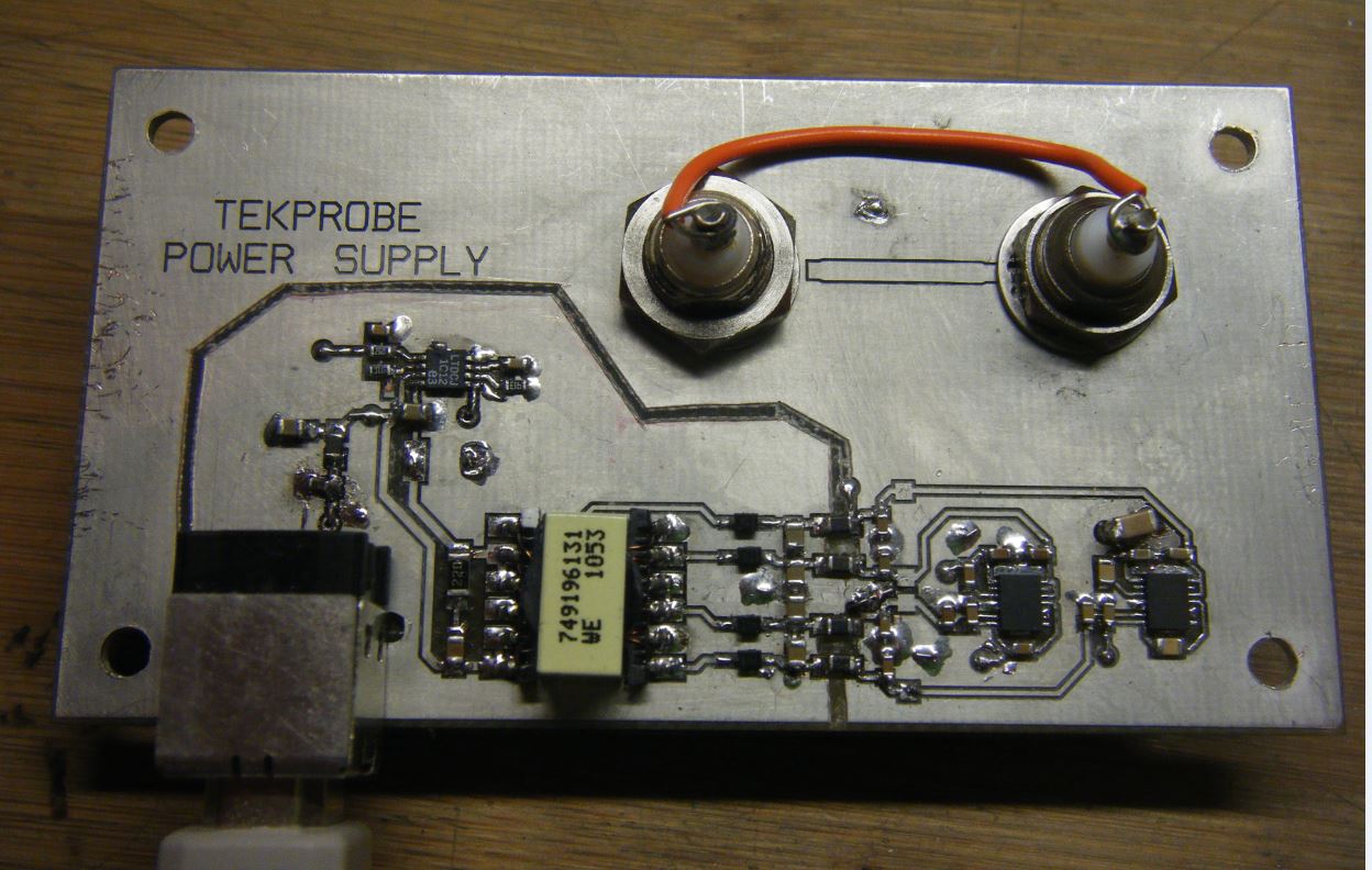


Photographs

Here are some photographs of the prototype. The board is 50 x 92 mm. I did not split the ground plane in my original design, so you can see the rework.


Here is a picture of the board with the probe attached. The BNC cable takes the signal to the scope.


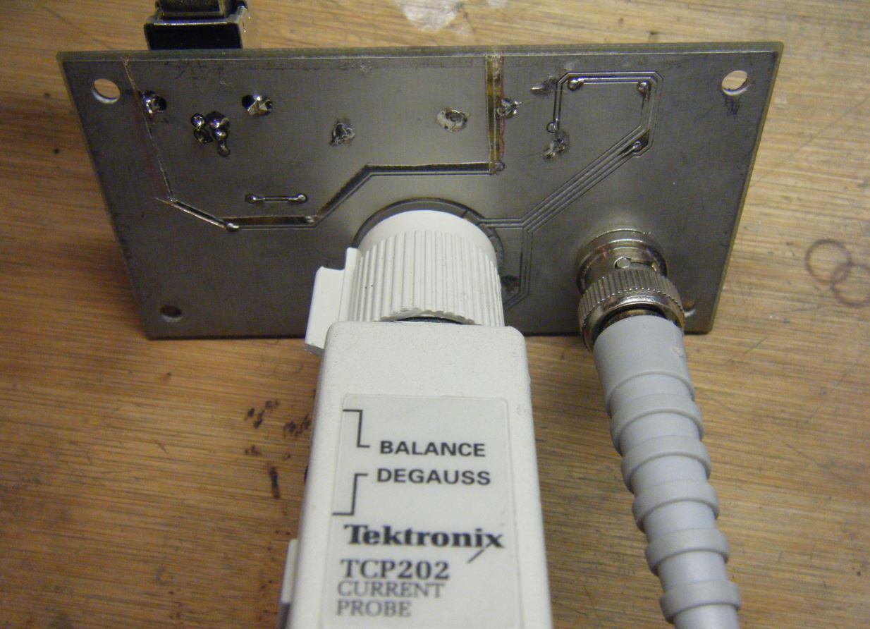
I plan on mounting the board in a small diecast box.


Testing

This first scope picture shows the noise floor. The scope is set to 2mV/div. You can see some spike at 1 MHz which originate from the flyback supply.


Here is a second picture showing the current measurement 5A pulsing a power supply with a dynamic load.


Regards,

Jay_Diddy_B


« Last Edit: March 07, 2015, 06:05:52 pm by Jay_Diddy_B »
 
The following users thanked this post: hendrix, nhzx0110wxd

Offline Someone

  • Super Contributor
  • ***
  • Posts: 4525
  • Country: au
    • send complaints here
Most probes wont need such a complex adaptor and will run fine on +/-12V:
https://www.eevblog.com/forum/testgear/tektronix-tekprobe-ada400a-to-agilent-autoprobe-mod/
you can even voltage program the probe to indicate its scaling:
https://www.eevblog.com/forum/projects/agilent-probe-interface-(-autoprobe-and-probe-id)/
 

Offline voltsandjolts

  • Supporter
  • ****
  • Posts: 2297
  • Country: gb
I been wanting to make something like this for a while, you beat me to it!  :-+  I have a P6245, P6243 and a ADA400 and it would be great to use them on scopes without the tekprobe interface. The official tekprobe adapter 1103 is old, cumbersome and expensive on eBay so this is a neat idea.

USB is a ubiquitous power source but some ports provide less than others before USB negotiation, it's great that the DSOX supply meets your needs. Remember the TCP202 uses more power when measuring higher currents (to balance the core at zero flux) so you might run out of power when measuring full scale 15A (or 1A with 15 turns in the jaw).

Your schematic says you are using 1N4148 diodes, Schottky would be better....but maybe that is what you really fitted.


Offline Jay_Diddy_BTopic starter

  • Super Contributor
  • ***
  • Posts: 2733
  • Country: ca
I been wanting to make something like this for a while, you beat me to it!  :-+  I have a P6245, P6243 and a ADA400 and it would be great to use them on scopes without the tekprobe interface. The official tekprobe adapter 1103 is old, cumbersome and expensive on eBay so this is a neat idea.

USB is a ubiquitous power source but some ports provide less than others before USB negotiation, it's great that the DSOX supply meets your needs. Remember the TCP202 uses more power when measuring higher currents (to balance the core at zero flux) so you might run out of power when measuring full scale 15A (or 1A with 15 turns in the jaw).

Your schematic says you are using 1N4148 diodes, Schottky would be better....but maybe that is what you really fitted.


Do you know if the P6243 and P6245 need the Offset feature that is included in the Tektronix 1103 ?

I test the adapter with a Bench supply. With the TCP202 attached the unit draws 0.25A from the 5V supply. I think I should be o.k. but I will check at high dc currents.

I was struggling with Schottky diodes versus the 1n4148. I was concerned about junction capacitance with the Schottky diodes. I am not really concerned about efficiency, I am more concerned about noise.
I will try some Schottky diodes.

Regards,

Jay_Diddy_B
 

Offline voltsandjolts

  • Supporter
  • ****
  • Posts: 2297
  • Country: gb
I wanted to check up on some specifications, I'll post them here so I don't lose them!

ADA400 Differential Amp
http://www.es-france.com/pdf/ADA400A.pdf
Uses +5V and +/-15V supply rails.
Edit: Does not use the Offset feature.

P6243 FET Probe
http://exodus.poly.edu/~kurt/manuals/manuals/Tektronix/TEK%20P6243%20Service.pdf
Uses the +/-5V supply rails.
Does not use the Offset feature.

P6245 FET Probe
http://exodus.poly.edu/~kurt/manuals/manuals/Tektronix/TEK%20P6245%20Instruction.pdf
Uses the +/-5V supply rails.
This DOES use the offset feature to extend the probe DC input range, however, I've never used it since all my measurements are within the standard +/-8V input range (Offset = 0V).
The 1103 Offset output has a range of +/-1V which extends the input range of the P6245 from -10V +/- 8V up to +10V +/- 8V (well, sort of, it's clipped at +/-15V but you get the idea).

Tek 1103 power supply outputs are rated 300mA from each of the four (+/-5V & +/-15V) supply rails, with 2% voltage accuracy. I presume its a linear supply, so relatively low noise.
http://www.trs-rentelco.com/Manual/TEK_1103_Manual.pdf

I see you tested the  TCP202 current draw at 250mA. Since the 1103 is only rated to 300mA, I guess TCP202 current won't increase much with increased measure current.

I doubt your supply could provide 300mA on all four supplies simultaneously (Edit: that's not a criticism! just highlighting the 1103 spec here), but I'll try measuring the real consumption of these probes. The FET probe consumption will be signal dependent since they drive 50 ohms.


« Last Edit: March 09, 2015, 08:16:34 pm by voltsandjolts »
 

Offline Jay_Diddy_BTopic starter

  • Super Contributor
  • ***
  • Posts: 2733
  • Country: ca
Hi,

I did look at the manuals. Here are the simplified block diagrams:


First the P6243, It looks like there is no active circuitry in the compensation box other than the serial memory. The active circuitry in the probe can not dissipate too much power on the probe would get too hot.


In the P6245, there is also op-amp for Offset control in the compensation box. Again the power dissipation will be limited in the probe.


I asked about offset controls, in case I need to add them to my interface. It seems that they are not needed.

Thanks,

Jay_Diddy_B
 

Offline 128er

  • Regular Contributor
  • *
  • Posts: 229
  • Country: de
Nice work! Like the idea to power it from USB.

Here is another thread about this topic:
https://www.eevblog.com/forum/testgear/tek-p5205-hv-differeantial-probe-teardown-btw-what-are-the-red-and-brown-wires/
 

Offline Jay_Diddy_BTopic starter

  • Super Contributor
  • ***
  • Posts: 2733
  • Country: ca
Nice work! Like the idea to power it from USB.

Here is another thread about this topic:
https://www.eevblog.com/forum/testgear/tek-p5205-hv-differeantial-probe-teardown-btw-what-are-the-red-and-brown-wires/

I had seen the 1103 clone that you designed and built in that thread. I stole the idea for Tekprobe connector from the thread!

You probably have a drawing like this somewhere  :D


Jay_Diddy_B
« Last Edit: March 09, 2015, 09:36:23 pm by Jay_Diddy_B »
 

Offline Jay_Diddy_BTopic starter

  • Super Contributor
  • ***
  • Posts: 2733
  • Country: ca
Hi group,

It has warmed up enough here in Canada for me to go in the workshop and do the metalwork for this project. Here are some pictures of the finished project.

First we have the project with a Tektronix TCP202 connected.


This what the unit looks like with the cables removed.


The circuit board is mounted on the bottom of the box with 3/4 inch standoffs.


This the hole cut in the side for the USB connector.


Regards,

Jay_Diddy_B
« Last Edit: March 18, 2015, 04:09:32 pm by Jay_Diddy_B »
 
The following users thanked this post: serg-el

Offline MarkL

  • Supporter
  • ****
  • Posts: 2124
  • Country: us
Nice job, Jay_Diddy_B!

The only thing I would suggest is to use a BNC-F to BNC-F jumper with coax in the middle instead of a strand of wire.  This is how the 1103 is built.

It doesn't matter much for the slower probes, but for the faster probes like the P6245 you'd want to maintain a continuous 50ohm impedance all the way to the scope to prevent artifacts from reflections.
 

Offline voltsandjolts

  • Supporter
  • ****
  • Posts: 2297
  • Country: gb

Yes, interesting post, thanks for sharing!
 

Offline Jay_Diddy_BTopic starter

  • Super Contributor
  • ***
  • Posts: 2733
  • Country: ca
Nice job, Jay_Diddy_B!

The only thing I would suggest is to use a BNC-F to BNC-F jumper with coax in the middle instead of a strand of wire.  This is how the 1103 is built.

It doesn't matter much for the slower probes, but for the faster probes like the P6245 you'd want to maintain a continuous 50ohm impedance all the way to the scope to prevent artifacts from reflections.

I might try using some of the Tektronix 'Peltola' connectors. These are unique to Tektronix. They were invented by Ron Peltola. From the pictures they look like they should work. They can only be obtained from surplus Tektronix equipment.


They use a cable like this:


These should be very familiar to people who have worked on Tektronix equipment.

They would certainly keep the signal shielded.

Thank you for your interest in my project.

Regards,

Jay_Diddy_B
« Last Edit: March 18, 2015, 09:05:42 pm by Jay_Diddy_B »
 

Offline 128er

  • Regular Contributor
  • *
  • Posts: 229
  • Country: de
Nice unit! I'm a little bit jealous about the form factor. And your layout of the pcb based Tekprobe connector is far better with the rectangular pads (like the original). My layout with the tiny round spots was a little bit hard to align. Matched only at the second spin of the pcb.


I might try using some of the Tektronix 'Peltola' connectors. These are unique to Tektronix. They were invented by Ron Peltola. From the pictures they look like they should work. They can only be obtained from surplus Tektronix equipment.

[...]

These should be very familiar to people who have worked on Tektronix equipment.

They would certainly keep the signal shielded.

Thank you for your interest in my project.

Regards,

Jay_Diddy_B

I wanted to also use this connectors. But i could not find them at my usual suppliers. I have only two of them with several short pieces of coax. Salvaged them from a high speed line scan camera.

Thank's for sharing your project!
 

Offline Griot06

  • Newbie
  • Posts: 3
  • Country: fr
Re: Tektronix TekProbe Power Supply for Agilent, Rigol and other oscilloscopes
« Reply #13 on: October 26, 2017, 02:08:58 pm »
Hello Jay_Diddy_B !

This is is , to me a very great project and I plan to do the same to connect my tek current probe to these DSO-X3034A from Agilent.
I succeeded in creating my allegro schematics (which I am a newbie with), but I am blocking on the tekprobe footprint. How did you get it ? Or where did you find the info to create it?

Then I also have 2 other questions:
- what is the purpose of the line of copper we can see on the top side of the board, between the 2 BNC connectors ?
- what is the aim of the via which can be seen on the top of it ? Is it to connect the grounds of the top and the bottom layer and  stabilize the potential ?

Thanks a lot in advance for your answers !
I hope to be able to quickly post my own version of your work.
 

Offline pigrew

  • Frequent Contributor
  • **
  • Posts: 680
  • Country: us
Re: Tektronix TekProbe Power Supply for Agilent, Rigol and other oscilloscopes
« Reply #14 on: October 26, 2017, 03:25:02 pm »
I also have a quick question/critique:

Should the connection of the two ground planes be extended so that it's underneath all of the ferrite beads? It's creating larger current loops than necessary how it's drawn. The same thing goes for the +16 FB net. Shouldn't it cross ground planes close to where the planes are connected?

- what is the purpose of the line of copper we can see on the top side of the board, between the 2 BNC connectors ?

My guess is that this was going to be used to connect the signals of the two BNC connectors. However, it looks like the lock-washer could be shorting signal to ground?
 
The following users thanked this post: Griot06

Offline Jay_Diddy_BTopic starter

  • Super Contributor
  • ***
  • Posts: 2733
  • Country: ca
Re: Tektronix TekProbe Power Supply for Agilent, Rigol and other oscilloscopes
« Reply #15 on: October 26, 2017, 06:14:07 pm »
Hi pigrew and Griot06,

Thank you for your interest in this project.

The copper line between the two BNC connectors was going to be a 50 Ohm transmission line. But, as indicated by pigrew the line gets shorted by the washer on the BNC connector. This can be seen in one of the photographs. I just used a wire, the orange wire, to hook the two BNCs together.

It would be better to use a shielded wire or the Tektronix Peltola connectors shown earlier.

Regarding the layout. I did the whole project in a day from start to finish. The original layout did not have the two separate ground areas. This was cut into the prototype artwork.

The split was to divide the USB ground from the scope's signal ground. I think the area around the beads is o.k. There is little pulsating current in the beads.

The ground return for the 16V FB is o.k.

I am not saying that the layout cannot be improved, I am saying that it worked well enough for my application, powering a TCP202 current probe.

Regards,

Jay_Diddy_B
 
The following users thanked this post: Griot06

Offline voltsandjolts

  • Supporter
  • ****
  • Posts: 2297
  • Country: gb
Re: Tektronix TekProbe Power Supply for Agilent, Rigol and other oscilloscopes
« Reply #16 on: October 26, 2017, 06:40:12 pm »
...but I am blocking on the tekprobe footprint. How did you get it ? Or where did you find the info to create it?

Download the Circuit Studio zipped project in this thread, it has some TekProbe info and DXFs in there:
https://www.eevblog.com/forum/circuit-studio/example-project-tektronix-tekprobe-adapterbreakout/
 
The following users thanked this post: Griot06

Offline Griot06

  • Newbie
  • Posts: 3
  • Country: fr
Re: Tektronix TekProbe Power Supply for Agilent, Rigol and other oscilloscopes
« Reply #17 on: October 27, 2017, 04:13:37 pm »
thanks to all of you for your replies.
And again congrats to Jay_daddy_b for this great project.

@ Voltsandjolts : Yes I  looked into these files. Thanks for sharing that quantity of info.  I was unfortunately unable to open the tekprobe4.dxf drawing (usign DXF viewer) while it worked fine with baseboard+bnc.dfx

In any case I was unable to ope any file today, either .SCN, .MAX or anything, even with the full Allegro Suite + viewers ... hurra !  :scared:
 

Offline KrudyZ

  • Frequent Contributor
  • **
  • Posts: 275
  • Country: us
Re: Tektronix TekProbe Power Supply for Agilent, Rigol and other oscilloscopes
« Reply #18 on: January 13, 2018, 11:21:38 pm »
For anyone else attempting to do something like this, a good source for the TekProbe socket would be the 11A52 or higher plugins for the 11k series of Tek scopes.
They come with a flex that terminates into 0'1" headers for the power signals and a coax cable coming out which terminates into the attenuator assemblies on the plugins.
These plugins are pretty inexpensive, especially when broken, but then the 1103 power supplies are also getting cheaper.
Just be warned, the lower speed plugins have an integrated socket / attenuator, so they would not be well suited for hacking.
 
The following users thanked this post: edavid, Neomys Sapiens

Offline Jay_Diddy_BTopic starter

  • Super Contributor
  • ***
  • Posts: 2733
  • Country: ca
Re: Tektronix TekProbe Power Supply for Agilent, Rigol and other oscilloscopes
« Reply #19 on: January 14, 2018, 04:26:53 am »
For anyone else attempting to do something like this, a good source for the TekProbe socket would be the 11A52 or higher plugins for the 11k series of Tek scopes.
They come with a flex that terminates into 0'1" headers for the power signals and a coax cable coming out which terminates into the attenuator assemblies on the plugins.
These plugins are pretty inexpensive, especially when broken, but then the 1103 power supplies are also getting cheaper.
Just be warned, the lower speed plugins have an integrated socket / attenuator, so they would not be well suited for hacking.


Thank you for you for your helpful comment.

I had looked at this at the time I started the project. I decided not to use the Tektronix flex pcb and include the tekprobe connector in my board.

Here is a picture, that I made at the time. It is the BNC connector assembly from a 11A71 plugin. As stated by KrudyZ, this would be a good way to implement the TekProbe connector.


Regards,

Jay_Diddy_B
 

Offline Griot06

  • Newbie
  • Posts: 3
  • Country: fr
hello !
It's now time for me to give you a brief status of my version of this project. I'm not done with it, but satisfying results are showing up.
Below you'll find a picture of the version of the schematics I intend to re-design, following several trials on the previous one. I just trimmed several components value around the MAX633, such as decoupling caps and the inductor value. And finally merged the 2 GND's together since I saw my noise peak-to-peak value reduced.

My main point is that, if the result with an external power supply is satisfying, I still have issue with the USB +5V input, which is noisy as hell. This noise is a 43kHz triangle, which corresponds to the oscillator of the max633 pushed in its limits.
As this noise (+ the offset) can't be seen with an external supply, I supposed it cames either (or both?):

- the impedance seen by the max633 input which could influence its results
- loop in the grounds which favor noise propagation/amplification

I checked the 5V USB supply from the oscilloscope, it's clean and can load 500mA without problem (here this is just a dozen on mA requested)

On the screenshots, green is the result using a Tek probe on an Agilent scope with this interface board, the blue one is the result with an Agilent Current Probe
« Last Edit: April 16, 2018, 01:04:31 pm by Griot06 »
 

Offline Johneecakes

  • Newbie
  • Posts: 2
  • Country: us
Hi, got a tcp202 at hamfest and want to build your power supply. I was wondering if you have the pcb design in gerber files or the like? There is a company called OSHPARK in Canada that takes pcb files and creates pcbs on the real cheap!! I just got to send them the right files; it sure would SAVE a lot of time. Thanks for your time.
Johneecakes.
 

Offline KrudyZ

  • Frequent Contributor
  • **
  • Posts: 275
  • Country: us
Hi, got a tcp202 at hamfest and want to build your power supply. I was wondering if you have the pcb design in gerber files or the like? There is a company called OSHPARK in Canada that takes pcb files and creates pcbs on the real cheap!! I just got to send them the right files; it sure would SAVE a lot of time. Thanks for your time.
Johneecakes.

Not sure how much your time is worth to you, but there is what seems to be a very good deal on a Tektronix 1103 on e-bay right now:
https://www.ebay.com/itm/Tektronix-1103-Tekprobe-2-Probe-Power-Supply/132624819501?epid=28019471482&hash=item1ee10e252d:g:jowAAOSwIzda~C7Y
(I have no connection to the seller)
 

Offline Johneecakes

  • Newbie
  • Posts: 2
  • Country: us
Hi, Im new to this blog thing and read your reply but it was too late... tek supply 1103 went for a good price.
Thanks for your  help.  -John
 

Offline Mosaic

  • Regular Contributor
  • *
  • Posts: 143
Re: Tektronix TekProbe Power Supply for Agilent, Rigol and other oscilloscopes
« Reply #24 on: February 23, 2020, 06:02:03 pm »
I have had a plan to do a similar project with the intent to make a few DIY for the community  to be sold via EBAY.
I have done this for the Tektronix SG-504 leveled sine wave 'head' , sold about 50 globally since 2016/2017. Not a big biz, but helps me invest in doing new designs in the field of vintage eqpt. longevity.


Thanks for all the insightful views. Time permitting I can take a look at this and perhaps have an available outcome that is cost effective for community.
My current project involves a smart hybrid battery to be added to regular ICE vehicles. Can't say more yet.


Share me

Digg  Facebook  SlashDot  Delicious  Technorati  Twitter  Google  Yahoo
Smf