I suggest DIN 41612. Used to be common for backplanes.
Thank you. This work out quite nicely. Fits the 100mmx100mm PCBWay board size for minimum price too.
They are not cheap. Circa $5 a piece with gold plating and non-gold versions are rare. From AliExpress they are still $2 each... and that brings me to my puzzle.
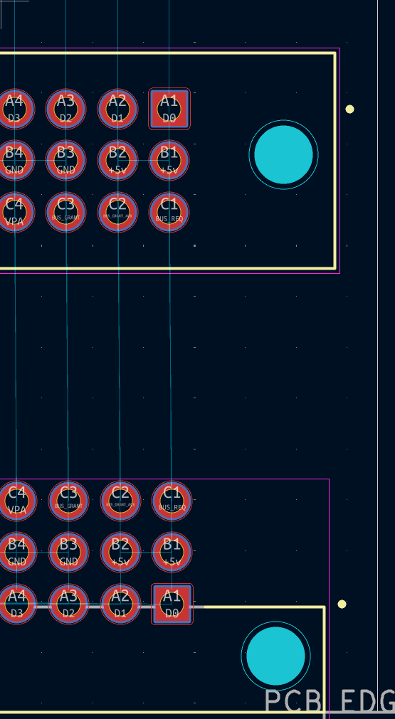
I was wondering why there were about 3 different copies of the same connector on Digikey. So I picked a straight female and a right angled male. Dropped them into KiCAD and... At first I was baffled, then I noticed. The pin out orientation is different. I had already been puzzling over geometry of having 2 "flat" end cards with 3/4 vertical expansion cards. CPU><EXP1><EXP2<>EXP3<>DEBUGCARD. For that to work with a "straight through" pin map, the last card (DEBUG) either needs to be upside down or I need to mirror the foot prints.
Then I noticed that the rightangled female and male have different pin mappings. The rows are mirrored.
The thing is... they are bit of bent metal, the don't care what you solder them to. Personally I don't care if the square pin 1 is in the right place or not.
KiCAD however... does care.
So... Do I spent another 30 minutes trying to check foot print pin orientation and down load the correct footprints and actually buy those specific connectors and not chance fate... or do I just open the footprint, select the pins and mirror them?
I suppose the more important quesetion is.... are the actual connectors mechanically keyed to force the matching pin oritentation. That could get messy and mirror imaging a foot print leads to tears and a dead board. Been there. "Bottom view" or "Boards view" footprints should be banned and their authors shot.
This is what I mean.

 Home
Home Help
Help Search
 Login
Login Register


