Recent Posts

Pages: [1] 2 3 4 5 6 ... 10 Next
1
Okay, this issue has now been resolved. It turns out that the solder flux I used (Kester 2331-ZX) had been absorbed into the hybrid substrate. The substrate became conductive, which formed a resistive path in parallel with the 1M input impedance. I found that submerging the hybrids in IPA and scrubbing with a brush did not reverse this unwanted conductivity. The only thing that worked was to soak the hybrids in flux remover, scrub, rinse in boiling hot water, scrub some more and blow dry.

This is the flux I'm using:
https://www.kester.com/DesktopModules/Bring2mind/DMX/API/Entries/Download?Command=Core_Download&EntryId=3679&language=en-US&PortalId=0&TabId=96

This is an "organic acid, water soluble" flux and it is stated that hot water should be used for cleaning. There is no mention of flux remover or IPA. I'm not sure what the ideal cleaning procedure is.

My recommendation is to measure the resistance between the Hybrid's BNC input pad and neighboring GND tabs before soldering back into the A15 attenuator assembly. The input relays are by default in the GND mode (input floating) so there should be infinite resistance. If you have any resistance, even tens of MOhms, it means you still have contamination on the board. The black relay is responsible for the DC/AC/GND setting and it is set to GND when unpowered.

My scope now passes SPC and there is roughly 0.250mV offset between the channels when in 1mV/div setting in 1M input impedance setting. I'm not sure how to actually use the 5mV/div, 2mV/div and 1mV/div setting because the scope will not allow me to select those fine vertical resolutions when I'm plugging passive probes in (min vertical resolution then becomes 10mV/div).

So, I consider this repair successful. Hopefully it will help someone else doing the same repair.

Thanks,
/John.
2
General Technical Chat / Re: Do you think an LED is a resistor?
« Last post by Zero999 on Today at 07:10:33 pm »
Perhaps a thyristor is another type of resistor, since it has ristor in it?

Nonsense. A resistive load will always result in unity power factor when connected to an AC source. A diode will not give unity power factor, when connected to an AC source, therefore it is not a resistor. End of discussion.
3
Other Equipment & Products / Re: Any opinions on the Aixun T420D?
« Last post by Tor Björn on Today at 07:07:20 pm »
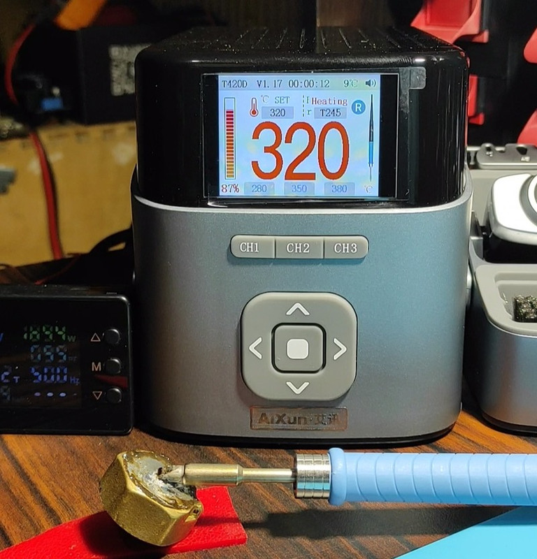
The T420 host is no different from the T420D except for the configuration, this has already been covered in this thread. I bought a T420 in the T245A configuration at a bestboard Store for $161.
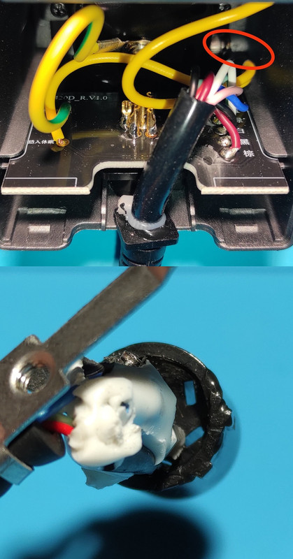
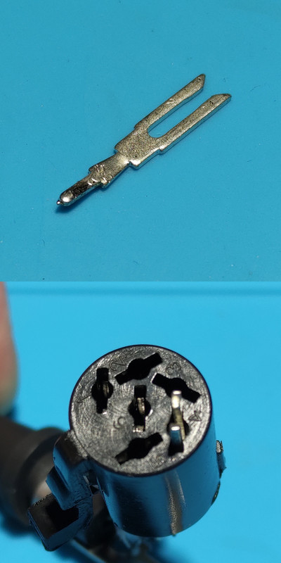
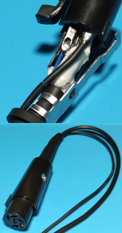
I'll tell how to ensure the operation of two handles (in my case T245A and T115A) with one holder. First of all, disconnect the yellow pair of wires inside the holder from the threaded bushing of the mast mounting screw. Next, you will need a donor contact for the aircraft connector of the T115A handle; I took an unused contact of pin #6 (ID) from the connector of another cheap T245 handle ($3 with coins). In the T115A connector remove part of adhesive to access to the hole for pin #4 (standby) and install the "donor" contact there. Solder the wire, the other end of which is connected to the mast in the area of the wing clamp.


Enjoy working with two handles and one holder at the same time.
Pin #3 is “extractor”, don’t get confused.
I bought the hangle (mast) with suspension (bracket) for the T115A separately in the same store, $6.67 with coins per pair. The T115A handle cost $5.75.
Gallery: https://postimg.cc/gallery/sWwPJw6
4
Repair / Re: HP54600B with spike problem with and without signal
« Last post by sacha on Today at 07:07:06 pm »
Thanks for the replies, your help is very important in finding the cause of this fault. all the tests done refer to U33 which is powered by 5V. All the signals we see are around 5vpp. I used the video number in reference to the pins of U33, video 1 = pin1, etc.... For the images you see I used the OE pin (22) as the trigger. And the suspicious shape is seen on the CE pin (20). During the tests I noticed that by touching only pin 20 with the oscilloscope probe the spikes attenuate. and I see that my probe set x10 puts 15 pf in parallel on pin 20. I will do as you said to put resistive loads on +5V and 0V and see what happens.

Opening a similar oscilloscope I realized that it has a RAM with a lower access time (70nS) I could try to replace U33 with a lower access time than the current 85nS.

The photo I posted describes the Memory I saw on the second Oscilloscope, the same but with U33 with an access time of 70 nS


Thanks again, I'll let you know as soon as I've tested it.
5
Looking at your pictures, I see that is was just your drawing stating the incorrect connection. But I also see in your picture you are using a scope probe to connect the signal generator to the reference resistor. This is not ok, as scope probes use resistive coax which can have quite a bit of resistance. Use a BNC cable with crocodile clips or something similar instead.

I would even recommend not to use scope probes for channel A & B also, but this should have less negative impact and the connection with the signal generator. However, I never used scope probes myself, I just used short BNC cables or a test jig...
6
Test Equipment / Re: Rigol ds1000z WFM file reverse engineering
« Last post by preamp.org on Today at 06:59:02 pm »
I have briefly tried Rigol's Ultra Scope software today. Might as well be that I missed something, but I was not able to load a WFM file with it. Looks like only CSV or something similar is supported. Which would reinforce my suspicion that not even Rigol has a tool to make sense of their own file format  :palm:
7
Test Equipment / Re: DMM Input Capacitance
« Last post by mawyatt on Today at 06:57:50 pm »
What's wrong with referencing earth at the outlet?

Nothing if you get the Allen Wrench into correct terminal  ;D

Best,
8
Thank you for your reply
I tried to upload other firmwares, but it didn't work I ordered a programmer to try to get a dump

Software Version 1.08

Hardware 1.00

Product Type ADS11023CAL+

Serial NO. 111020S1403103596
9
I watched the videos of L&R Tempo 400 in action, as the head moves through the four jars. Quite the washing machine, spin cycle included lol. No idea where the watch parts are inside the drum, I couldn't handle Rolex mech in there spinning and getting banged up it seems.
Piezos have gone lead free, berylium free.
The generator board, only need to know its freq. and tuning cap, AC voltage would help. I don't think you can get a lot more amplitude with new donuts as it's ultimately limited by the generator board, how much power it puts out. If you put Frankendonut in there, could you get 10x the agitation and wash? I don't think so.

Maybe reach out to some of these people:
https://www.thorlabs.com/newgrouppage9.cfm?objectgroup_id=11059
https://www.pi-usa.us/en/products/piezo-transducers-sensing-ultrasound/piezoelectric-ceramic-rings
https://www.piceramic.com/en/products/ultrasonic-transducers/power-ultrasonic-transducers maybe the same
https://en.honda-el.co.jp/product/ceramics/lineup/piezoelectric_ceramics/pzt

A custom donut is not a big deal aside from the electrodes, they water-jet cut them. I did not look at chinese ones, they are literally $10 each.
I guess the large ID is for the motor shaft to fit through?

As to your questions, the parts are in a mesh basket which contains smaller mesh baskets.  For pieces w/ shock jewelling, we remove the cap jewels and insetting (the hole jewel w/ bushing) and leave the balance in the movement.  We leave the setting lock spring in its seat. This is the safest and has never failed me.

The basket is at the end of the motor arbor which passes through the can tube in the transducer can.  The tansducer is a two piece assembly.  The lid which attaches to the motor housing and the can which contains the donut.  The can is a press fit with an oring to keep solutions out should you overfill your jars.  The solution should only come 1/2 way up the can when the basket and motor assembly are lowered into the jars.

The cleaning system has not changed in 50 years.  Only the cost of new machines.

BTW, I owe you.  And I am serious.
10
Test Equipment / Re: DMM Input Capacitance
« Last post by KungFuJosh on Today at 06:55:22 pm »
What's wrong with referencing earth at the outlet?
Pages: [1] 2 3 4 5 6 ... 10 Next