Recent Posts

Pages: [1] 2 3 4 5 6 ... 10 Next
1
The second method with breaking the loop at the inverting input and inserting an AC source is the easiest. For comparison, breaking the loop at the output and inserting there an AC source isn't exactly the same and should give some gain and phase deviations in the Bode plot for very high frequencies. Breaking the loop at the output is usually the place where you would put an injection transformer to make (invasive) gain/phase measurements in real life.

Another simple method that shows open loop gain, loop gain and phase (margin) is attached.
2
Beginners / Replacing SRAM IC with Flash
« Last post by VEGETA on Today at 07:30:21 am »
Hello,

Can I replace an SRAM IC with Flash one and still get the system to work as intended?

The project is for N64 memory pak which has original SRAM IC inside (LH52256) and it can be replaced easily to FRAM chips like FM18W08-SG and FM28V020-SG but these are very expensive.


I have a project in mind to have multiple Flash ICs to be switched in order to have lots of memory space instead of just one memory chip like original, but I read that flash cannot be used instead of ram chips. however, flash chips are very cheap compared to fram ones.

an mram\fram solution already exists which is not cheap and still has only one memory ic which means same capacity as original, just without battery and will retain save. I want to make multiple memory banks in one pak but in a cheaper way.

what do you think about this?
3
Repair / Re: Keithley 2400 locks up when buttons are pressed
« Last post by Le_Bassiste on Today at 07:29:56 am »
did you try the steps as outlined in chapter "Battery Replacement" of the service manual, especially the ":SYST:MEM:INIT" sequence?
also, i wouldn't trust the EEPROM sockets on the digital board too much, you could pull and give them a "deoxit & re-seat" treatment.

as for the key pads, a key pad repair kit for tv remotes will do the trick. iirc, the stuff i used was "gumki do pilotów" by TermoPasty.pl from a*n. i glued the new pads right on top of the button stakes without even removing the old pads, using a drop of high temperature silicone (instead of the silicone that was supplied in the kit) and letting them cure for 24 hrs. button feel is slightly "stiffer" now, but key responsiveness works like a charm since 3 years now.

edit: forgot to mention: you may want to check the electrolytic caps  :horse:
5
Test Equipment / Re: Siglent SDS800X HD 12 bit DSO's
« Last post by rf-loop on Today at 07:22:17 am »
Imho, this is a feature. For now. Whether it can be optimized / improved somehow,  remains to be seen. Of course it is nice if there is way to do it so that is works independently.

At least in my case, this feature has never made it difficult to use the machines for their intended purpose as a tool. I classify it mostly as a cosmetic "disadvantage" for now.

I see it the same way with a 500€ scope like the 800.

However, with one for €4000, it would be nice if this cosmetic slip-up was fixed.

Many things are nice to have.  :D

(What kind of signal measurement and analysis does that fact prevent or even make difficult?
And yes, also I like  IF  this "feature" can improve but only IF it is possible in such a way that the mouse response is not slowed down in any function from the current response speed, in fact there are functions where it perhaps should be further accelerated, i.e. the mouse response..)


Well yes bottom model aound 4k  but ... SDS3104X HD (750MHz model (partially 1GHz)).
Consumer prices:
€ 7,116.20 incl. 19% VAT
€ 7,415.20 incl. 24% VAT
€ 7,594.60 incl. 27% VAT
6
Microcontrollers / Re: RIP Z80
« Last post by peter-h on Today at 07:21:02 am »
Quote
If you try to sell an MCU to many large customers now they show no interest unless it has an ARM core

That however is a reasonable approach.

Nowadays, with a 168MHz core, 99% of applications can be done with 1 or 2 chips e.g. the 32F4xx. These have been around > 10 years, even the chinese do copies, the dev kits are free and well understood by anyone using them, the chips are $5 in quantity, and they are 10x to 100x fast enough for most jobs. I've just done a project with a 32F417 and I am certain I will not need to look at another CPU in the rest of my actuarial life expectancy (20 years). With ETH and USB done and working (not optimally but well enough) and with 21MHz SPI, I can do absolutely anything I have done since 1980 and absolutely anything I can imagine having to do. For highly specialised stuff e.g. a modern DSLR one needs specialised chips, but for nearly all "industrial control" and consumer stuff, more is not needed.

The most important thing is preserving in-house dev expertise, because devs tend to care little for "your" company, and love picking the latest fancy parts (good for the CV, too) so you have to steer them to using the right parts. You can always tell when some company doesn't do this correctly; you get crap like 10.1k resistors all over the place :) I can show you some Honeywell autopilot schematics...

The Z80 performed this job for many years. There was simply no point in using the other "8/16" bit CPUs, for embedded work. And it had the massive advantage of a short learning curve. The RM was maybe 200 pages. All the product schematics ended up pretty much the same basic stuff. Today you have a 300 page DS, 2000 page RM, ~5000 pages ARM32 CPU RM... building up expertise with a popular chip has never been more important.

What buggered the Z80 and Zilog, before the right time, was the 64k addressing. IAR C got around it reasonably well with their Large Model but linear addressing have the 68k a good start. Had the Z80 had even 20 bit addressing, a lot of other chips would have never got off the ground.
7
Beginners / Re: Convert US standard 115V to International 230V
« Last post by radiolistener on Today at 07:14:06 am »
As mentioned above, 240V mains usually has 50 Hz, while 120V mains have 60 Hz, so if you're needs to convert 120V@60Hz to 240V@50Hz it cannot be solved with simple 1:2 voltage transformer.

There are two approaches to solve it:

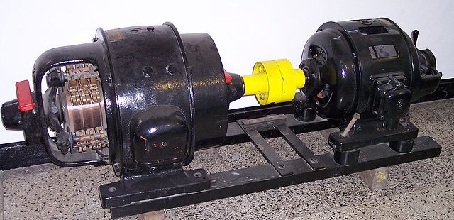
1) Old approach is to use umformer (electric motor + alternator). In your case the motor will work from 120V@60Hz and the alternator will generate 240V@50Hz. This way was widely used in old military equipment where voltage/frequency conversion is required (they often are designed for 400 Hz AC power source).

For example:


2) Modern way is to replace power supply in your equipment with switching mode power supply that support both standards.
8
Repair / Re: Desoldering advice
« Last post by indeterminate on Today at 07:12:31 am »
You need to yous a very large iron
300w 1/2" diameter tip
sumthing like this https://www.ebay.com.au/itm/295097210355
get it up to temperature and then turn it off
make a heavy copper wire bridge between all the pins that need to be desoldered  at least 2.5mm2
that way you can heat everything at once and pull the relay out.
The tip of the soldering iron should be at least 1/2" diameter and 2 > 3 inches long , including the bit inside the element.
9
Today, I received my  Keithley 617 with very good condition. it was made in 1991 or 1992, and last cal time is 1999. when I power on it, on current and 2pA mode, no input, the read is change from 20 counts to 300. Now, I have work to do. ;D. maybe need clean the pcb first and change the capacitors .
10
FPGA / ATF1502 programming & 'wrong' id (fake?)
« Last post by dolbeau on Today at 07:07:41 am »
Hello,

Tl;DR: are my ATF1502ASL fake, pre-programmed, or did I misunderstood?


I have a (hobbyist) design that involves an ATF1502ASL CPLD. Long story short, I have some assembled PCBs back from JLCPCB (they sourced the parts), and I'm now trying to program the ATF1502ASL using JTAG. I have a known-to-work SVF file (I'm reworking an existing design in a different from factor, SVF is from the original designer), a USB blaster clone seen by 'openocd', and the appropriate JTAG header on the board.

However, out of 5 boards:
* On three of them I see a single 'tap' with 'expected-id' of 0x03a1407f
* On two of them I see a single 'tap' with 'expected-id' of 0x0151203f

As far as I understand from the SVF file I got, the ATF1502ASL should be 0x0150203f. The first variant ID doesn't even show up as Atmel but as Silicon Storage Technology...

I did try to program one of those ATF1502ASL (type 0x03a1407f, as that's the board I finished assembling with THT parts) with the known-good SVF file; openocd stopped as one of the early step is:
Code: [Select]
SIR 10 TDI (059);
SDR 32 TDI (ffffffff)
        TDO (0150203f)
        MASK (ffffffff);
And the output doesn't match, as the ID is wrong.

So I patched the ID in the SVF file to 03a1407f in the SVF, and then openocd was happy - the programming went fine. There's some more TDO checks later in the file, but I'm not sure that's enough to say it's at least ATF1502ASL-compatible... anyway, the design doesn't appear to work for now, but that could be for a number of reasons so it's not definitive.

So my questions...

(a) Is that normal to have such JTAG IDs in the parts? Am I paranoid or did I misunderstood something?
(b) If it's not normal, are they fake, pre-programmed, ... ? Is there a way for me to tell? Should I complain to JLCPCB?
(c) Is there some way to tell what the parts really are from the JTAG ID?

Thanks in advance!
Pages: [1] 2 3 4 5 6 ... 10 Next