This was being thrown away about 2 years ago at a previous job, and I got the go-ahead to strip it for useful parts before it got hauled out; thought I'd take some photos while I was at it. Apologies for the heavy flash glare, weird white balance, and generally awful photography: had to do this in a dimly-lit equipment room.
One of the main parts of an MRI scanner are the gradient coils: there are generally 3 of these, one for each physical axis (X, Y, and Z directions), and they're used to create magnetic field gradients across the interior space of the scanner. These gradients are necessary to separate the magnetic resonance signals from different areas of the patient, and reconstruct an actual 3-dimensional image rather than just a single undifferentiated pixel (like the NMR machines used by chemists, where they don't care about the spatial aspect). The details and physics of this have been explained much better by other people, so go read up on MRI gradients if you're interested. What this requires on the electronics side, though, is power amplifiers that can push very high currents through these coils (in the 100s of amps min.) while also being able to put high voltages across the coils to ramp the currents up or down quickly (in the 100s of volts min.). Modern switch-mode Gradient Power Amplifiers (GPAs) made for high-field MRI systems usually have a 3-phase feed along with water cooling in giant cabinets, and can output multiple kV/kA per channel. This system here though, from the early 2000's judging by IC date codes, will turn out to use only linear amplifiers, and looks like it's meant for much smaller power levels.


Overall, there's a control & readout box on top, and a rack with 3 large amplifiers and one small 3-channel amplifier (top). There's also a giant mess of cabling in the back, not shown here.
Control section

This is the brains of the operation for the 3 large amplifiers (likely X, Y, and Z). A digital board at the back (top-right) with a Siemens CPU accepts commands from a more central MRI computer over an external D-sub connector. This then feeds digital data to the 3 channels of the DAC board (top-left). The setpoints from the DAC board then make it (possibly by way of the supervisor board in the middle) to a set of two stacked pre-emphasis boards. These modify the setpoint signals in a way I'll describe shortly, and then output the final X, Y, and Z current setpoint signals from the back, to be fed to the 3 large amplifiers. Meanwhile, these amplifiers are returning output current measurements to this control section: the current measurements are both watched by the "supervisor board" in the middle, which seems to compare them against the DAC signals and watch for overcurrent and out-of-regulation events to shut down the power stages if there's a fault, and to the display board at the front of the enclosure which generates the bargraph displays of output on each gradient channel.


 Pre-emphasis
Creating a desired magnetic field inside a coil with known geometry is pretty straightforward at DC. However, when the current in the coil is changing, the changing field induces eddy currents in the metal structures nearby. With radios, etc. open solenoid coils are normally kept away from large pieces of metal specifically to avoid eddy currents and their effect on inductance and losses: however, in an MRI scanner, having metal near the gradient coils is unavoidable, with the large Dewar that holds the superconducting magnet providing the static field, and even the superconducting coil itself should have some significant coupling to the gradient coils. This ends up having a low-pass filtering effect on the magnetic field ramp-up and ramp-down slew rate - this diagram illustrates it very nicely, along with how the waveform can be "pre-distorted" to compensate for the effect:
https://www.mriquestions.com/what-is-pre-emphasis.htmlI'm not sure exactly how the pre-emphasis works in this Bruker GPA, but rather than being done all digitally as it would be handled today, the pre-emphasis board here likely has a multi-stage digitally-programmable filter for each channel, so that its step response can be carefully shaped to be the
inverse of the gradient-coil-with-eddy-currents step response. There's 2 stacked boards to serve 3 channels, each with 9 identical sections, so that adds up to 6 filter sections per channel.
Globally, there's a few OP27 op-amps to handle the inputs & output signals, as well as an AD7514 SPDT analog switch. An Altera(?) programmable logic device of some kind seems to be responsible for digital interfacing.

Each identical filter section has a 3x OP27 op-amps and an OP15 op-amp, some large 100 nF film caps (presumably for lower-distortion/more precise filter responses than ceramics at the time could provide), an AD7547 dual 12-bit multiplying DAC, and an AD7590 quad SPST analog switch. I'm guessing that the multiplying DACs are used as a programmable-gain element as part of a programmable filter response (the AD7547 datasheet even shown an example application circuit using 2 as a programmable state variable filter, although this applies to all multiplying DACs:
https://www.analog.com/media/en/technical-documentation/data-sheets/AD7547.pdf).
Large amplifier


Inside, these look identical to a high-power linear audio amplifier, which were actually what was used to drive gradient coils in early MRI experiments. As well as a giant transformer and control-power board at the bottom-left corner here (inc. some logic, relays, and power resistors for pre-charging bulk capacitors), you can see the power stage's bipolar DC supply in the form of the four large metal-can capacitors at the left, and the bridge rectifier attached to the heatsink.
There are two back-to-back heatsinks, each with its own power board that contains many paralleled transistors in TO-3 packages.

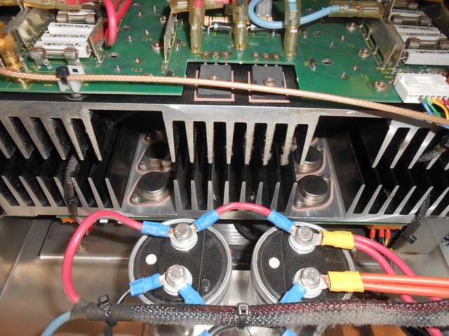
Those diode pairs in TO-247 packages seem to be for clamping the output voltage (important with an inductive load) while the two transistors at the left edge, on either side of the thermal-cutout switch, I believe are pre-drivers for the combined base connections of the transistor arrays.

Each power transistor has its own emitter resistor for current sharing, and its own fuse:
You can see some of the biasing components up on posts, likely selected then added as part of the testing/calibration process to match the individual board.

Under that metal shield at the lower-left of the inside overview is the control board, which contains the output-current control loop, as well as some digital signals (shutdown, fault reporting, etc.):

One fun thing about the large amps is these compensation adjustments, made via a set of DIP switches on the front panel. When running a constant-current control loop that drives a voltage across an inductive load, the load's impedance directly affects the control loop response and stability, and so to be able to make the amplifier work well with a variety of gradient coils (a range of both load inductances and resistances), the control loop values need to be adjusted. Today the control loop would probably run inside a DSP (which allows for more complicated control schemes, auto-compensation tuning, and all kinds of other nice things) but in this case it was just done by selecting capacitors with switches, and changing a resistance with a multi-turn pot:


