Author Topic: 858 analog hot air rev eng schematic and mod suggestion  (Read 1325 times)

0 Members and 1 Guest are viewing this topic.

Offline doktor pytaTopic starter

  • Frequent Contributor
  • **
  • Posts: 488
  • Country: pl
858 analog hot air rev eng schematic and mod suggestion
« on: June 13, 2020, 12:16:36 pm »
After long operation (~1h) my hot air refused to heat. I've checked heater- OK (cold resistance approx. 70 ohm).
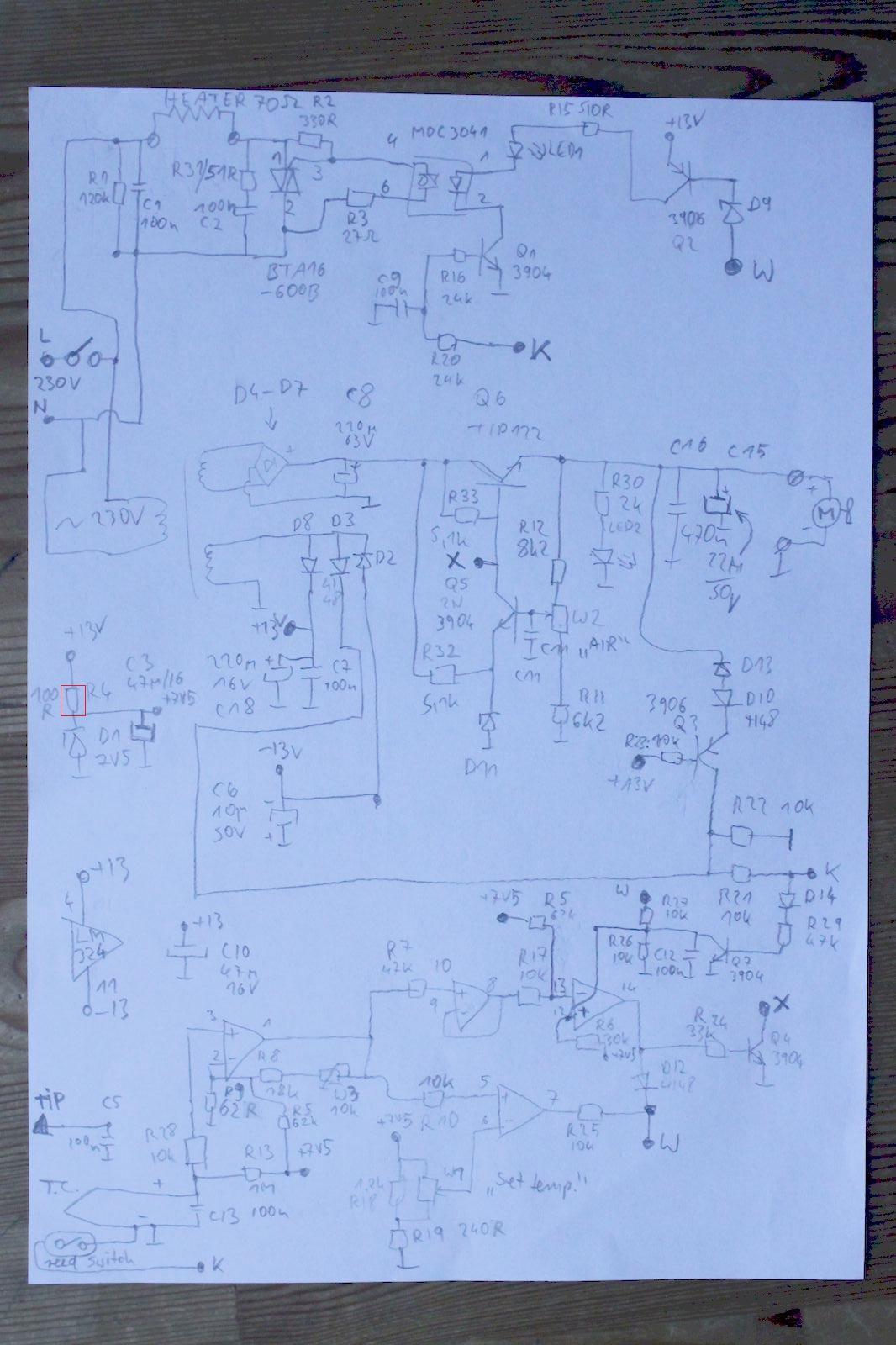
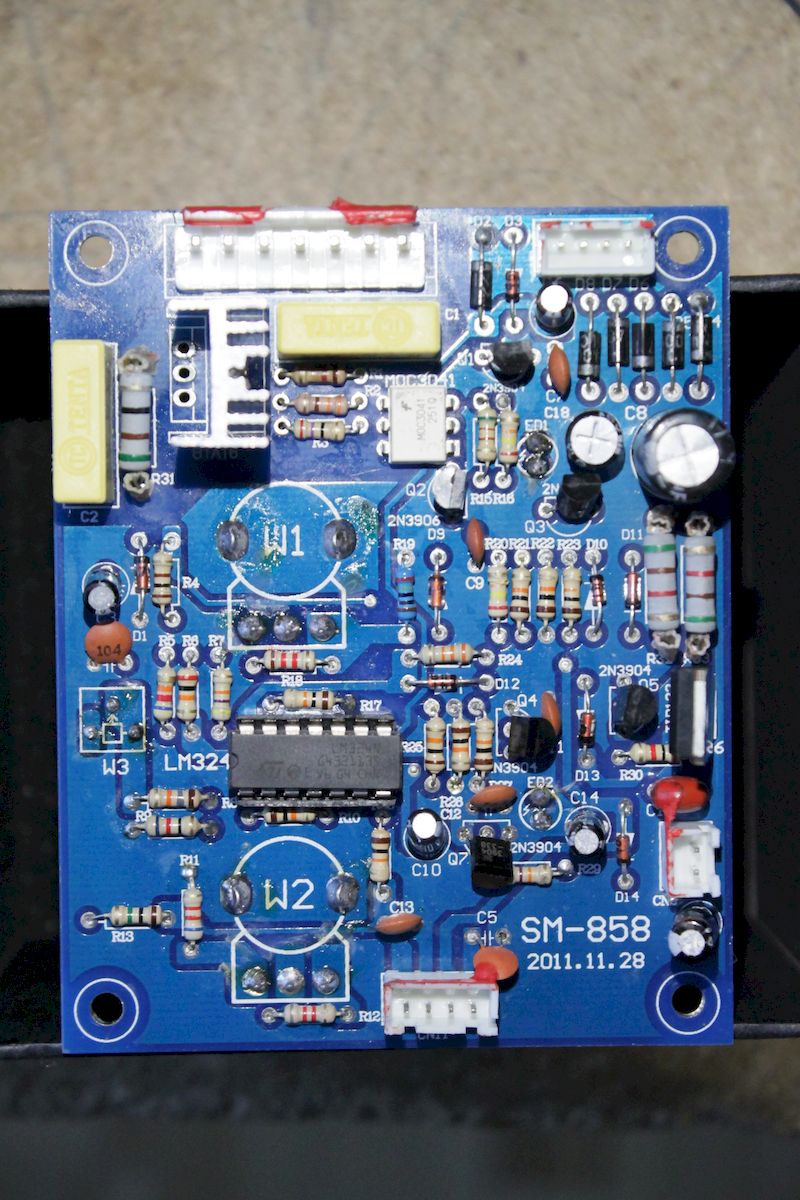
I decided to draw schematic from the PCB to understand what is going on.
The failure was open R4 instead of 100R. It dissipates about 160mW 300mW.
This resistor biases 7V5 Zener which is the only regulated voltage in this device (!).
My suggestion is to increase the resistance to 220R but this change may affect temperature calibration.
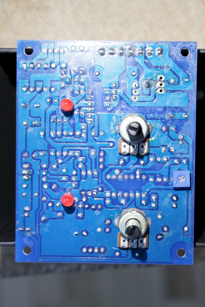
So after this mod I used thermocouple thermometer to calibrate the device using front panel accessible 'CAL' potentiometer.


« Last Edit: August 05, 2020, 03:53:03 pm by doktor pyta »
 

Offline aqibi2000

  • Regular Contributor
  • *
  • Posts: 211
  • Country: gb
Re: 858 analog hot air rev eng schematic and mod suggestion
« Reply #1 on: June 14, 2020, 09:15:04 am »
Good going!!
Tinkerer’
 

Offline fzabkar

  • Super Contributor
  • ***
  • Posts: 2263
  • Country: au
Re: 858 analog hot air rev eng schematic and mod suggestion
« Reply #2 on: June 15, 2020, 07:55:18 pm »
AISI, the voltage across R4 is 5.5V (= 13V - 7.5V), so the power dissipation is about 300mW.

If you increase the resistance, then the Zener may not regulate properly at higher load currents.
 

Offline doktor pytaTopic starter

  • Frequent Contributor
  • **
  • Posts: 488
  • Country: pl
Re: 858 analog hot air rev eng schematic and mod suggestion
« Reply #3 on: June 15, 2020, 10:09:16 pm »
Fzabkar, thanks for pointing out bad value typed.
Voltage of +13V rail drops to 12V when heater is at maximum power.
I still claim that it is a bad idea to pass 45mA through 7V5 Zener (340mW into 400mW rated diode) and dissipate 200mW in 250mW rated resistor.
Whole PCB has no ventilation and is further heated by linear fan controller circuit.
If You carefully analyze the schematic You will see that there is no significant loading on +7V5 rail.
« Last Edit: June 16, 2020, 08:30:45 pm by doktor pyta »
 

Offline fzabkar

  • Super Contributor
  • ***
  • Posts: 2263
  • Country: au
Re: 858 analog hot air rev eng schematic and mod suggestion
« Reply #4 on: June 16, 2020, 12:27:32 am »
Yes, I agree that your mod is OK. Sorry, I should have looked closer at your diagram. I'm surprised that the resistor failed before the Zener. Usually it's the other way round.
« Last Edit: June 16, 2020, 12:31:06 am by fzabkar »
 

Offline aqibi2000

  • Regular Contributor
  • *
  • Posts: 211
  • Country: gb
Re: 858 analog hot air rev eng schematic and mod suggestion
« Reply #5 on: June 16, 2020, 10:13:44 pm »
Chibesium resistor, doesn’t meet the power dissipation specified. I don’t find this surprising
Tinkerer’


Share me

Digg  Facebook  SlashDot  Delicious  Technorati  Twitter  Google  Yahoo
Smf