Author Topic: agilent 6632B fault, repair, and several design flaws  (Read 28443 times)

0 Members and 1 Guest are viewing this topic.

Offline Dr. FrankTopic starter

  • Super Contributor
  • ***
  • Posts: 2382
  • Country: de
agilent 6632B fault, repair, and several design flaws
« on: September 04, 2016, 01:11:51 pm »
I bought an agilent branded 6632B system power supply.
It's built end of 1999, owned by NOKIA, and last calibrated in 2006. Maybe it was used afterwards for a few years w/o further calibration.


On unpacking, it smelled strongly, like being stored for a longer period of time in humid condition.
It powered on, and operated properly, but all parameters were off a bit.
After successful calibration, everything was spot on during verification.

On the 2nd day, it worked for a few minutes only, then it went into protected mode, and errors 1, 2, 3, 4, 5, 80, 11 came on simultaneously.
That bunch of error messages indicated, that the communication between the main processor and the analogue part, like FPGA, EEPROM, A/Ds, D/As, and so on, failed.


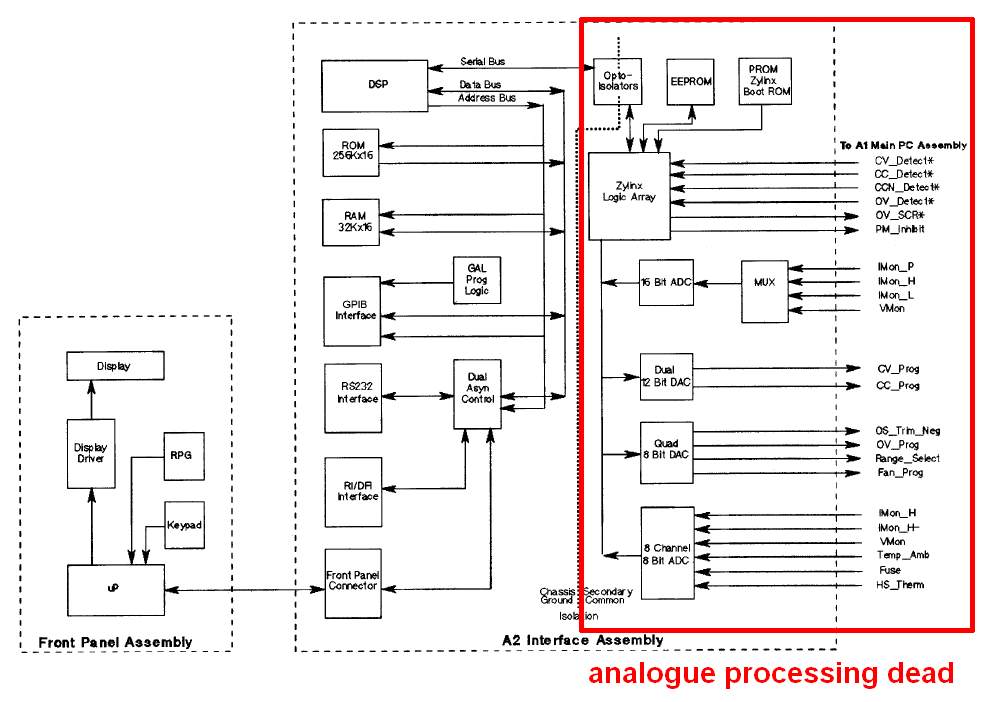
It turned out, that the analogue circuits were not powered any more, as the +/-15V, +5V supplies were completely dead; F300 and F301, two 4A mini-fuses, were blown.
So the fault would probably be located somewhere in the analogue power supply components.


The most suspicious Ta caps C496, C497 showed no short, when measured relative to GND.
It was also possible to power + 15V (220mA) and - 15V (-48mA) by an external PSU.. even the fan came on.

So in first instance, I replaced the mini-fuse by two multi-fuses.
When powering the unit on again, it did a big bang, followed by a sizzling noise, and the Magic Smoke escaped from one of the suspicious Ta caps.
Now, both of them (1µF, 35V) were short.


I replaced them with 100nF SiBaTit caps, blue components, which should be sufficient for this purpose.


The unit now powered on w/o any problem, even the calibration was still fine.

The error root causes up to now:

1) Thou shalt not place Ta-caps directly on power entry
2) Thou shalt have resistors in series with Ta-caps, about 5 Ohm/Volt, to limit current and dI/dt

But that's not the end of the story, yet.
 
When I tried to measure the voltage directly across one of the replaced caps, expecting about 25V, I got no reasonable reading.

That was very strange, but a test of their common point showed no connection to ground.
So I assumed, that the over-current burnt the PCB trace.
But neither on top, nor on bottom of this two-layer-board, there was a trace to GND.


So both caps had been put in series, 55V in total across them.
The voltage distribution between both caps was undefined, maybe only given randomly by their individual leakage currents, so that one of them might have been loaded with the full 55V:

3) Thou shalt have a voltage balancing resistor network, if you place capacitors in series
4) Thou shalt not place too high voltage over Ta-caps, good reliability requires max. 2/3 of nominal voltage

Ta caps may withstand 30% overvoltage (surge voltage), for short time periods. Constant overvoltage will reduce their reliability and lifetime greatly.
After all, 25V as intended, would have been ok.
One of the capacitors may have had failed before, and the humidity inside their mold compound, or the drying of the components may have sped up the fault mechanism.

Now, the final root cause was revealed by looking closely into the schematics:
The design engineer simply forgot to place a dot on the line crossings, between the caps and the GND line.


Well, this unit was obviously produced for 20 years, in thousands of pieces, with these 3 fold design flaws, and I wonder, how many units failed due to this.
As this PSU family will be terminated mid of next year, I doubt that Keysight will make a further service note on this issue.

Frank

PS: Forgot to mention, that I of course bodged in a wire from GND of the 7815 to the common point of both capacitors, on the bottom side of the PCB.
I recommend to replace the Ta capacitors, also.

These ugly stickers, i.e. the calibration and the NOKIA inventory stickers, can be removed by carefully heating them with a hair dryer (not too hot!), and then peeling them off with a plastic scraper
« Last Edit: September 05, 2016, 08:09:57 am by Dr. Frank »
 
The following users thanked this post: oPossum, bdivi, Smokey, HighVoltage, doktor pyta, tfm, hoppppla

Online wraper

  • Supporter
  • ****
  • Posts: 16847
  • Country: lv
Re: agilent 6632B fault, repair, and several design flaws
« Reply #1 on: September 04, 2016, 01:18:48 pm »
2) Thou shalt have resistors in series with Ta-caps, about 5 Ohm/Volt, to limit current and dI/dt
Really? Then you may just not use tantalum capacitors at all because it becomes pointless.
« Last Edit: September 04, 2016, 01:24:50 pm by wraper »
 

Offline Dr. FrankTopic starter

  • Super Contributor
  • ***
  • Posts: 2382
  • Country: de
Re: agilent 6632B fault, repair, and several design flaws
« Reply #2 on: September 04, 2016, 01:34:37 pm »
2) Thou shalt have resistors in series with Ta-caps, about 5 Ohm/Volt, to limit current and dI/dt
Really? Then you may just not use tantalum capacitors at all because it becomes pointless.

Correct!

These Ta-caps can't be used in hi-rel. applications, on fast rising voltage/current nodes.
If you can limit the dI/dt by other means, e.g. behind the voltage regulator, you can omit these series resistors.

In our automotive applications, by design rules, it's strictly forbidden to use them on battery entry, i.e. clamp 15 / 30.
For reliability and safety reasons, causing cars burning down completely, Ta caps should not be used at all in automotive applications, and be replaced by MLCCs.. which have other problems..

Frank
« Last Edit: September 05, 2016, 08:58:14 am by Dr. Frank »
 

Offline lukier

  • Supporter
  • ****
  • Posts: 634
  • Country: pl
    • Homepage
Re: agilent 6632B fault, repair, and several design flaws
« Reply #3 on: September 04, 2016, 03:20:43 pm »
Well spotted. I have two 6632B (bought some time ago from KJDS) and fortunately no problems so far, excellent power supplies, the only drawback is size/weight for 100W power rating.

I'm planning to design and build an aftermarket Option 760 (to have psuedo-SMU), got the parts already, so next time I'll be opening the PSUs I'll check these caps.

You might want to check the service notes against your serial number. There were multiple "Unit exchange program" notes or one even related to a capacitor problem (6632B-03A, but on the front panel board).
 

Offline KJDS

  • Super Contributor
  • ***
  • Posts: 2442
  • Country: gb
    • my website holding page
Re: agilent 6632B fault, repair, and several design flaws
« Reply #4 on: September 04, 2016, 05:41:30 pm »
That's terrible circuit drawing. I hate dots on cross junctions, if you want to make a connection, have the two vertical lines meet the horizontal one at different points.

Offline Dr. FrankTopic starter

  • Super Contributor
  • ***
  • Posts: 2382
  • Country: de
Re: agilent 6632B fault, repair, and several design flaws
« Reply #5 on: September 04, 2016, 06:57:51 pm »
I'm planning to design and build an aftermarket Option 760 (to have psuedo-SMU), got the parts already

You might want to check the service notes against your serial number. There were multiple "Unit exchange program" notes or one even related to a capacitor problem (6632B-03A, but on the front panel board).

Did that SN scan already, and also found no hint.
SN 6632B-09 of course has been implemented during this repair.

Would you mind sharing your relay option? I'm also interested...

Frank
 

Offline lukier

  • Supporter
  • ****
  • Posts: 634
  • Country: pl
    • Homepage
Re: agilent 6632B fault, repair, and several design flaws
« Reply #6 on: September 04, 2016, 07:25:00 pm »
Would you mind sharing your relay option? I'm also interested...

So far I just guessed and ordered the components. Based on the HP part numbers and Find-A-Part, using the data provided there I've ordered the following components  from Farnell:
V23105-A5303-A201 - 3 pcs - small signal for sense lines,
ST2-DC12V-F - 2 pcs - main output relays,
MC1413PG - darlington array, ULN2003 probably could work as well but I went with the HP part,
98267-0233 - 8 pos 1 mm pitch FFC cable for the control lines from the MCU board,
68610814422 - connector for this FFC

the only missing bit is the connector for J620 - power and sense lines from the main PSU board. I don't care that much so I thought I'll bend and solder B9PS-VH(LF)(SN) connector between the main and the option board, or just use a bunch of wires from an old ATX PSU. There are some fuses and resistors on the sense lines in the service manual schematic, but I don't know if this is really necessary.

Surely, when I finish and test my design I can publish it here, but I cannot promise anything, as now I'm focusing on submitting my PhD thesis, so all the electronic projects are on a back burner.
 
The following users thanked this post: bateau020

Offline Dr. FrankTopic starter

  • Super Contributor
  • ***
  • Posts: 2382
  • Country: de
Re: agilent 6632B fault, repair, and several design flaws
« Reply #7 on: September 04, 2016, 07:30:40 pm »
Would you mind sharing your relay option? I'm also interested...

So far I just guessed and ordered the components. Based on the HP part numbers and Find-A-Part, using the data provided there I've ordered the following components  from Farnell:
V23105-A5303-A201 - 3 pcs - small signal for sense lines,
ST2-DC12V-F - 2 pcs - main output relays,
MC1413PG - darlington array, ULN2003 probably could work as well but I went with the HP part,
98267-0233 - 8 pos 1 mm pitch FFC cable for the control lines from the MCU board,
68610814422 - connector for this FFC

the only missing bit is the connector for J620 - power and sense lines from the main PSU board. I don't care that much so I thought I'll bend and solder B9PS-VH(LF)(SN) connector between the main and the option board, or just use a bunch of wires from an old ATX PSU. There are some fuses and resistors on the sense lines in the service manual schematic, but I don't know if this is really necessary.

Surely, when I finish and test my design I can publish it here, but I cannot promise anything, as now I'm focusing on submitting my PhD thesis, so all the electronic projects are on a back burner.

Great hints! Thank you.

Good efficiency for your thesis, what'll be the subject?
 

Offline lukier

  • Supporter
  • ****
  • Posts: 634
  • Country: pl
    • Homepage
Re: agilent 6632B fault, repair, and several design flaws
« Reply #8 on: September 04, 2016, 07:45:33 pm »
Good efficiency for your thesis, what'll be the subject?

Thanks! The working title is "Rapid Room Understanding from Wide-Angle Vision", mobile robotics + computer vision, focusing on the indoor household robotic platforms similar to the Dyson 360 Eye robot (crazy optics!).  Some of the initial work was already published here:
https://www.doc.ic.ac.uk/~rl2712/papers/LukierskiR_ECMR15.pdf
 

Offline HighVoltage

  • Super Contributor
  • ***
  • Posts: 5468
  • Country: de
Re: agilent 6632B fault, repair, and several design flaws
« Reply #9 on: September 11, 2016, 04:15:08 pm »
Dr.Frank,
Impressive, that you found such a design flaw.

I have one of these stacked away and not used in years. May be time to check what you have found.
There are 3 kinds of people in this world, those who can count and those who can not.
 

Offline HighVoltage

  • Super Contributor
  • ***
  • Posts: 5468
  • Country: de
Re: agilent 6632B fault, repair, and several design flaws
« Reply #10 on: September 24, 2016, 11:44:50 am »
Today I opened my 6632B to check if it has the same missing ground connection.
And yes, indeed it has.
Most chips have a date code of 1116

Interesting, that this fault was not corrected during the many updates this PSU went through.
Here are my pictures of the bodged ground connection

There are 3 kinds of people in this world, those who can count and those who can not.
 

Offline saturnin

  • Regular Contributor
  • *
  • Posts: 116
  • Country: cz
Re: agilent 6632B fault, repair, and several design flaws
« Reply #11 on: September 24, 2016, 02:15:35 pm »
Dr. Frank, good catch!  :-+

Although, I own older version of the PSU - HP6633A (with LCD display), your repair thread made me check service manual for HP663xA units. As I expected, I found a corresponding +/-15V bias supplies circuitry. Fortunately, the design flaw is not there - 1u capacitors are not installed in older units (see attached screenshot).


Offline hoppppla

  • Newbie
  • Posts: 4
  • Country: de
Re: agilent 6632B fault, repair, and several design flaws
« Reply #12 on: September 25, 2016, 08:31:39 pm »
Dr.Frank,

thanks a lot for your error description an the good pictures. My unit had the same problem, just without the smoke  :)
Replaced the tantals and the fuses and all problems are gone  :-+
 

Offline senseless

  • Contributor
  • Posts: 32
  • Country: de
Re: agilent 6632B fault, repair, and several design flaws
« Reply #13 on: September 26, 2016, 05:38:09 pm »
Hmm, just a few months too late for me, so I had to figure it out myself. Exactly the same problems with these tantalum caps and burnt fuses. Probably also due to high humidity. I have replaced these tantalums with 50V MLCC ones back then hoping they will not fail due to aging/humidity. But I did not realize the design flaw with the missing ground connection. So thanks for sharing!
I had it on the TODO list to write some lines about my fix here in the forum until today. Fortunately, I can remove it from there now after having your nice description here :)
 

Offline free_electron

  • Super Contributor
  • ***
  • Posts: 8517
  • Country: us
    • SiliconValleyGarage
Re: agilent 6632B fault, repair, and several design flaws
« Reply #14 on: September 26, 2016, 07:33:56 pm »
death to ALL tantalum caps !
Professional Electron Wrangler.
Any comments, or points of view expressed, are my own and not endorsed , induced or compensated by my employer(s).
 

Offline eblc1388

  • Frequent Contributor
  • **
  • Posts: 394
  • Country: gb
Re: agilent 6632B fault, repair, and several design flaws
« Reply #15 on: January 06, 2017, 04:53:13 am »
Do not just provide the missing earth point without replacing the two tantalum capacitors.

I did and ended up blowing two 4A fuses on power up. It turns out that one of these capacitors was in fact faulty but the fault was masked by the other series good capacitor.

Thank Dr Frank for sharing.

 
« Last Edit: January 06, 2017, 09:15:22 am by eblc1388 »
 

Offline babysitter

  • Frequent Contributor
  • **
  • Posts: 893
  • Country: de
  • pushing silicon at work
Re: agilent 6632B fault, repair, and several design flaws
« Reply #16 on: February 24, 2017, 02:41:49 pm »
No design flaw but something you should be aware of: Its sinking current when you press "Output off" . Hard and fast (If rear panel switch in FAST position at least.)

This might lead to catastrophic effects in the attached device.

I just had a device attached to the 6632B which happens to use a step-down converter for current-limited/voltage-limited (2 voltage levels, 14.4V for recharging, 13.8V for float charge) sealed-lead-acid battery charging. Everything was fine until i switched off the output of my 6632b, when two current measurement resistors located between charger and battery/rest of the circuit started releasing magic smoke. Replacing the resistors got it back to life but I assume:

  • Power supply was switched off by me, sinking the input caps of the step-down
  • body diode of mosfet turned on by battery voltage bridged step-up secondary to primary
  • battery discharged thru resistors and body diode into the 6632b in sink mode (CC too high for this)
  • resistor BBQ

Of course it was aggravated by the battery but a bunch of electrolytics might have a similar effect.
I'm not a feature, I'm a bug! ARC DG3HDA
 

Offline HighVoltage

  • Super Contributor
  • ***
  • Posts: 5468
  • Country: de
Re: agilent 6632B fault, repair, and several design flaws
« Reply #17 on: February 24, 2017, 02:57:28 pm »
Many Agilent / HP power supplies have a crowbar circuit built in that gets activated when the PSU is turned off.
I learned this the heard way with a brand new Agilent PSU many years ago.
These PSU's are not ideal to charge a battery or large capacitor

From the 6632 Manual:

OVP Considerations
The dc source’s OVP circuit contains a crowbar SCR, which effectively shorts the output of the dc
source whenever the OVP trips. If an external voltage source such as a battery is connected across the
output and the OVP is inadvertently triggered, the SCR will continuously sink a large current from the
battery, possibly damaging the dc source.
To avoid this, program the OVP setting to its maximum value to prevent it from inadvertently tripping.
Additionally, an internal fuse is connected in series with the SCR. This fuse will open to prevent large
currents from damaging the SCR. If this internal fuse has opened, The FS status annunciator will be set.
Refer to the Service Manual for instructions about replacing this fuse.
In addition, the OVP circuit’s SCR crowbar has been designed to discharge capacitances up to a specific
limit. These limits are:
Agilent 6631B 127,000 mF.
Agilent 6632B and
66322A
50,000 mF.
Agilent 6633B 20,000 mF.
Agilent 6634B 10,000 mF.
If your load capacitance approaches this limit, it is recommended that you do not intentionally trip the
OVP and discharge the capacitance through the SCR as part of your normal testing procedure, as this
may lead to long-term failure of some components.

There are 3 kinds of people in this world, those who can count and those who can not.
 

Offline babysitter

  • Frequent Contributor
  • **
  • Posts: 893
  • Country: de
  • pushing silicon at work
Re: agilent 6632B fault, repair, and several design flaws
« Reply #18 on: February 24, 2017, 07:10:04 pm »
Yes, a firing crowbar will lock the device in conducting mode, would have been worse. The debugging consisted after a while of contemplating mostly of "Did I just? Lets see if there are problems which point at something else."

I'm not a feature, I'm a bug! ARC DG3HDA
 

Offline mtdoc

  • Super Contributor
  • ***
  • Posts: 3575
  • Country: us
Re: agilent 6632B fault, repair, and several design flaws
« Reply #19 on: February 24, 2017, 08:26:01 pm »
Wow - what an enlightening thread!   I was aware of the potential issue with the SCR/current sinking but Dr. Frank's fault finding and design fail discovery is news to me.  Very timely since I have a 6632b on it's way now from a recent eBay purchase.  Will definitely check this and correct the issue if needed.  Will double check that my 6632a does not have this issue as well.

Kudos to Dr. Frank for his detective work and especially for an excellent explanation that even a novice like me can understand. :-+
 

Offline Dr. FrankTopic starter

  • Super Contributor
  • ***
  • Posts: 2382
  • Country: de
Re: agilent 6632B fault, repair, and several design flaws
« Reply #20 on: February 25, 2017, 06:36:21 am »
Wow - what an enlightening thread!   I was aware of the potential issue with the SCR/current sinking but Dr. Frank's fault finding and design fail discovery is news to me.  Very timely since I have a 6632b on it's way now from a recent eBay purchase.  Will definitely check this and correct the issue if needed.  Will double check that my 6632a does not have this issue as well.

Kudos to Dr. Frank for his detective work and especially for an excellent explanation that even a novice like me can understand. :-+

Thank you!

Somebody else already found out, that this flaw does not affect the A version.

Frank
 

Offline Smokey

  • Super Contributor
  • ***
  • Posts: 2572
  • Country: us
  • Not An Expert
Re: agilent 6632B fault, repair, and several design flaws
« Reply #21 on: July 16, 2022, 09:46:15 pm »
Bump for a great electronics detective story. 
 

Offline TiN

  • Super Contributor
  • ***
  • Posts: 4543
  • Country: ua
    • xDevs.com
Re: agilent 6632B fault, repair, and several design flaws
« Reply #22 on: July 17, 2022, 06:39:54 am »
Nice story indeed. I should check my 6652A and 6653A as well as 6629A PSUs.
YouTube | Metrology IRC Chat room | Let's share T&M documentation? Upload! No upload limits for firmwares, photos, files.
 

Offline free_electron

  • Super Contributor
  • ***
  • Posts: 8517
  • Country: us
    • SiliconValleyGarage
Re: agilent 6632B fault, repair, and several design flaws
« Reply #23 on: July 18, 2022, 04:39:24 am »
check the capacitor just left of the VFD. that thing has the wrong voltage rating installed in a bunch of serial numbers. those caps short out , brining down one of the regulators and the supply does not start.
it's a 1210 ceramic part.
Professional Electron Wrangler.
Any comments, or points of view expressed, are my own and not endorsed , induced or compensated by my employer(s).
 

Offline Dr. FrankTopic starter

  • Super Contributor
  • ***
  • Posts: 2382
  • Country: de
Re: agilent 6632B fault, repair, and several design flaws
« Reply #24 on: July 18, 2022, 07:58:25 am »
check the capacitor just left of the VFD. that thing has the wrong voltage rating installed in a bunch of serial numbers. those caps short out , brining down one of the regulators and the supply does not start.
it's a 1210 ceramic part.

Hello free_electron,
how can you tell this? Do you have schematics or BOM for the display and µC PCBs? (all these are board level repair only)
If not, how could one find out the rating of this 1206 ceramic capacitor, and how to identify the intended / possible voltage across this component? Could you provide any pictures, please?

Thank you!
Frank


Share me

Digg  Facebook  SlashDot  Delicious  Technorati  Twitter  Google  Yahoo
Smf