Author Topic: BK Precision 2160A repair  (Read 49722 times)

0 Members and 1 Guest are viewing this topic.

Offline ZaUcYTopic starter

  • Contributor
  • Posts: 25
BK Precision 2160A repair
« on: June 25, 2014, 01:09:09 am »
Hello,
First time posting, and I am new to the blog.  I searched for the BK 2160A but there didn't seem to be much about repair, so sorry if this post is redundant.

So I bought a BK 2160A, for $50, because I just graduated and need to start building up my lab equipment collection.  As shown in the picture, the oscilloscope does power on, the CRT still works and is still very bright, the controls seems to be responsive, and there is some wave displayed.  I figured since the scope seems to be mostly working, fixing it should not be that hard, but I'm having a little trouble.  As you can see in the picture, the cal signal is displayed sort of curved square wave missing the falling edge.  I am borrowing an "Analog Discovery" from a friend to test the scopes cal signal, but I need to buy a micro-USB cable.

condition of the scope:
Very nice condition! it looks like someone bought this scope in 1997 and stored it in the original packaging(which it came with) until now.  The inside of the scope is equally as nice as the outside with minimal dust (I will post inside pictures later).

What I have done:
I have measured the low voltage rails, 5-16V, and all seem nominal.  There are some mid-range rails, 140-200V, that I will measure later because my DMM/probes are supposed to handle up to 1000V.  I am having trouble confidently probing around the scope due to two rails at -1.9kV and 12kV!!!

There is nothing visibly wrong with any components, but I still need to start testing the R/C/D values.  With all that said, I guess my main questions are:

1)  Is there an obvious culprit for waves looking like this?  Where should I mainly focus my debugging?

2)  When is it safe to probe around the scope when all the HV circuitry is near?  Is simply disconnecting the power from the scope and cycling the power sufficient to drain any residual energy?

(When I have access again, I will be posting detailed internal pictures of the scope and the entire scopes schematics)
Thanks
 

Offline Purevector

  • Contributor
  • Posts: 32
Re: BK Precision 2160A repair
« Reply #1 on: June 25, 2014, 01:16:11 am »
Maybe its just me, but it seems you simply need to change your vertical resolution.  You are set to 5 mv/div if I am reading that right.  Try going to 1 or 5 v/div.  The test signal is probably 1Vp-p or something along those lines.
 

Offline tautech

  • Super Contributor
  • ***
  • Posts: 28335
  • Country: nz
  • Taupaki Technologies Ltd. Siglent Distributor NZ.
    • Taupaki Technologies Ltd.
Re: BK Precision 2160A repair
« Reply #2 on: June 25, 2014, 03:07:53 am »
It is unwise to display a waveform on a CRT scope in such a manner that ALL the vertical waveform is not on the screen.
This condition is stressing the vertical output amplifiers.

Start with a sufficiently high input attenuator setting and then adjust for close to FSD.

The falling edge is there, you just can't see it with those settings.
Try a falling edge trigger setting and you should see it.
Avid Rabid Hobbyist
Siglent Youtube channel: https://www.youtube.com/@SiglentVideo/videos
 

Offline What_NZ

  • Regular Contributor
  • *
  • Posts: 150
  • Country: nz
Re: BK Precision 2160A repair
« Reply #3 on: June 25, 2014, 09:07:40 am »
Maybe its just me, but it seems you simply need to change your vertical resolution.  You are set to 5 mv/div if I am reading that right.  Try going to 1 or 5 v/div.  The test signal is probably 1Vp-p or something along those lines.

The CAL terminal is 2Vp-p so turn the CH1 VOLT/DIV Knob to the 0.5V or 1V position. Also make sure the VOLT/DIV Knob is pushed in.
« Last Edit: June 25, 2014, 09:11:00 am by What_NZ »
 

Offline ZaUcYTopic starter

  • Contributor
  • Posts: 25
BK Precision 2160A repair (Updates)
« Reply #4 on: June 25, 2014, 04:56:02 pm »
Hey,

Response:
So I know it looks like I just have my V/div turned down too low, but I am 100% certain that is not the issue (I have just revisited adjusting the knob settings).  If necessary, I can upload a video of myself adjusting the scope settings while measuring the cal signal?

Update:
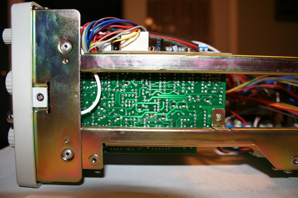
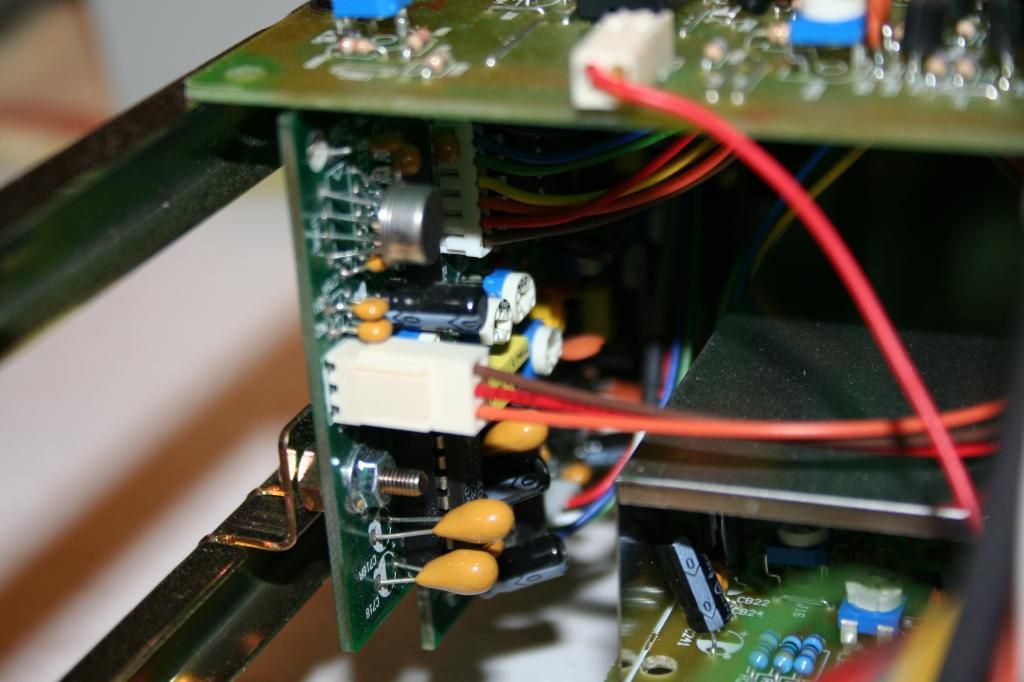
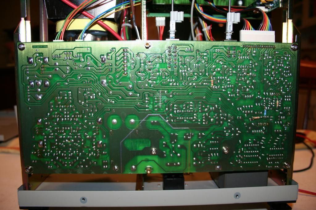
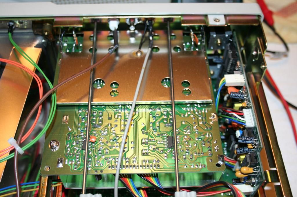
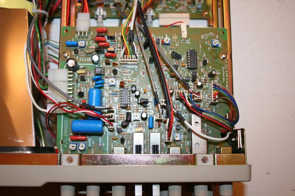
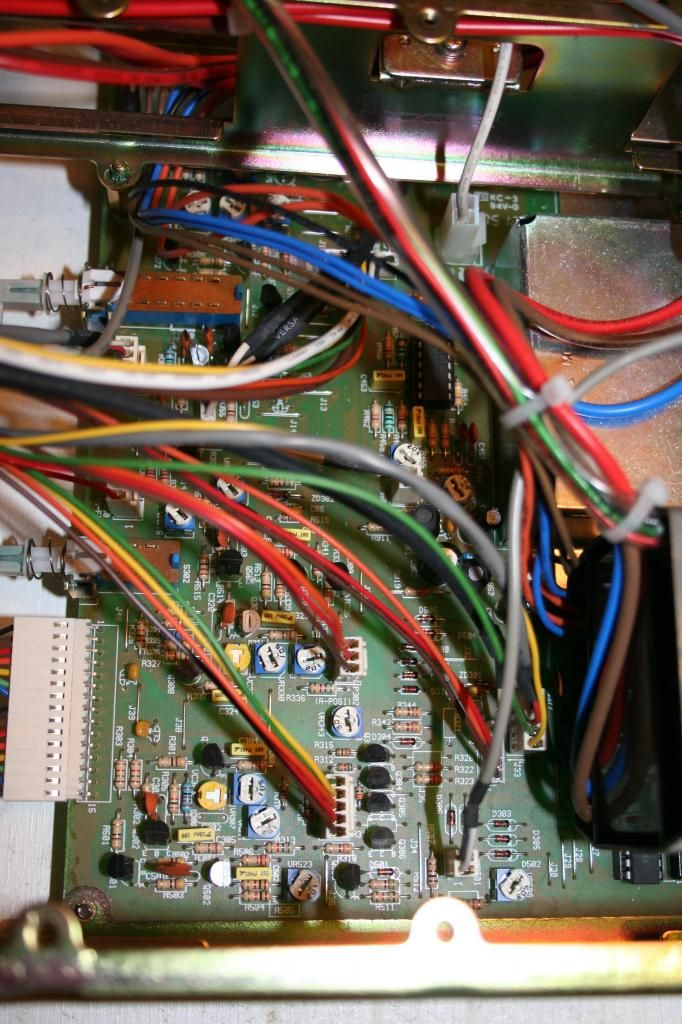
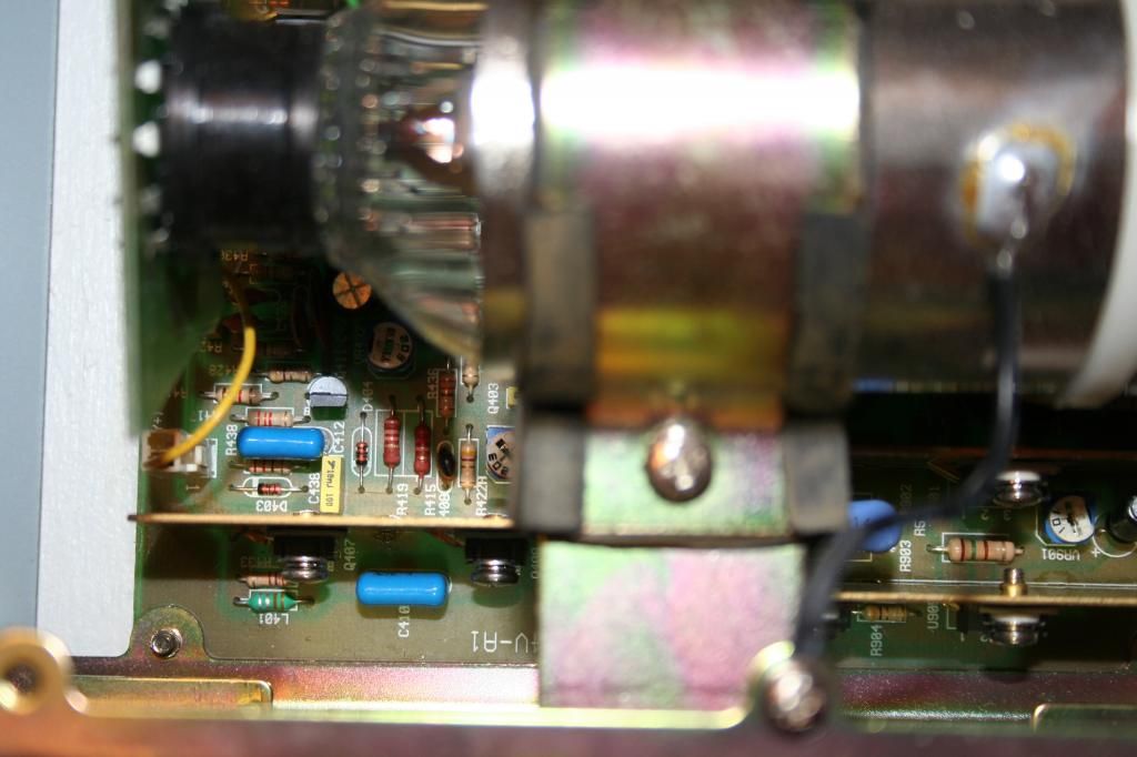
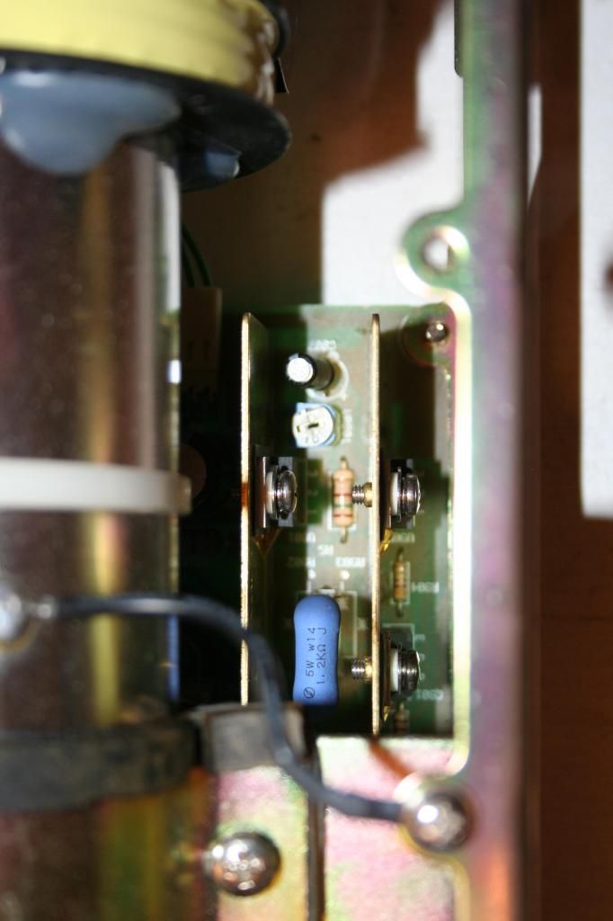
So I have uploaded some close up pictures of the internals.  Sorry if they don't show much, it's hard to get good internal shots will all the wires in the way and board mounted awkwardly.  I have also uploaded scans of the original schematics for the 2160A model.  However, the board layouts seem to be slightly out of sync with my scopes boards.  As you can see, the schematics show versions D,F, etc., where my boards seems to be on revision A.

In one picture I have uploaded, you can see that I am testing the cal signal from my Oscope (2Vp-p, 1kHz) with both the Oscope and a USB "Analog Discovery."  The Oscope's cal signal seems to be spot on, but I am still getting a bad reading on my Oscope.  One thing I noticed is that the trigger level seems to do absolutely nothing to the measured signal on my Oscope, that doesn't seem right!

I probed around some more for all the sub-HV rails, and all the voltage rails seems to be fine.  However the two two 16V differential pairs coming off the main transformer were both reading out a stable 20V, is this something to worry about?  Every other rail was within +/-1% of the designed value.

Questions:
1) Is there somewhere I can probe around to test for my trigger signal?  I have two rear BNCs labeled "Z-axis input" and "CH-B(Y) Signal Output."

2) With all the High Voltage circuitry present, when is all the residual energy dissipated and safe for me to probe around?  Some of these boards are buried in the chassis and I would like to remove them for easier examination safely.

3) What else should I be doing to further debug my Oscope?  I am feeling kind of lost right now :/

Thanks!
 :-BROKE

!!!Here are the Schematics to the scope!!!
https://drive.google.com/file/d/0Bzao2JBCAMY0YWYtbFFJLW9xcFk/edit?usp=sharing


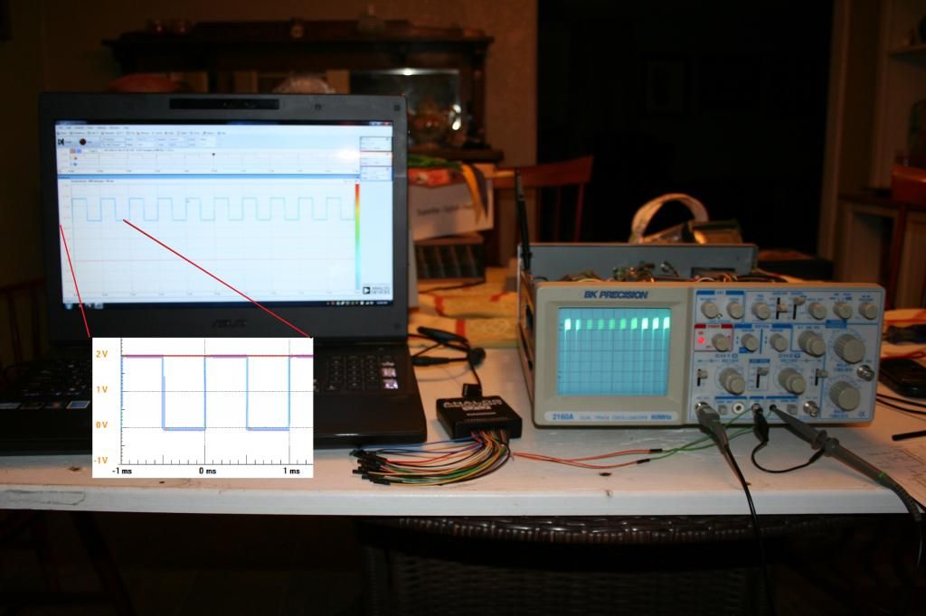
Solder side of PSU board


Solder side of vertical amplification circuit (I believe)


Component side of CRT control, trigger, and possibly position and time pos. circuit


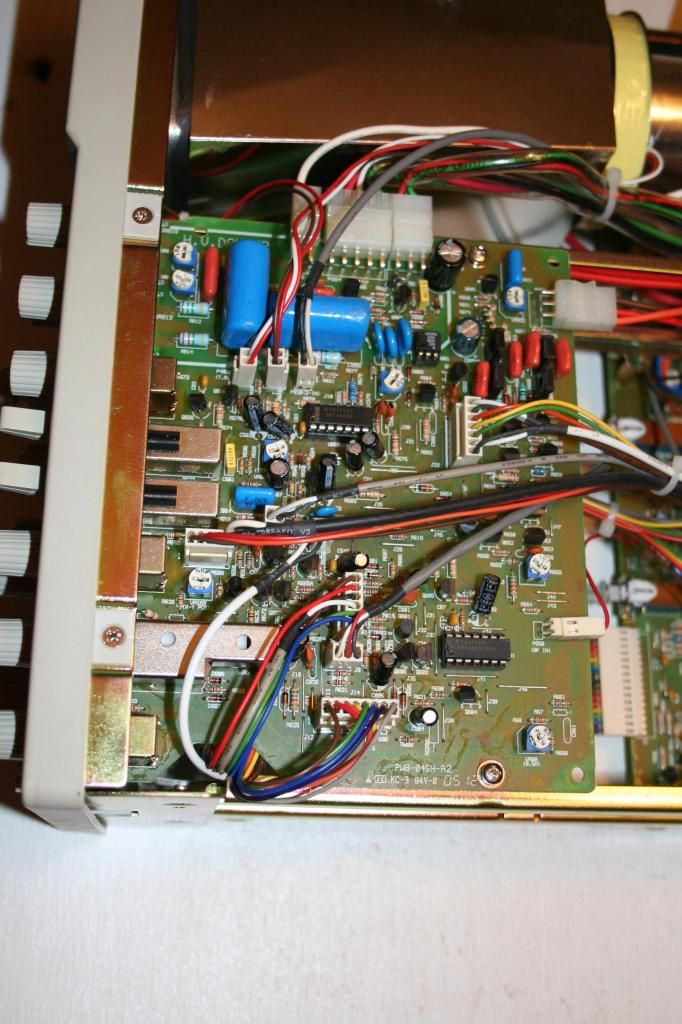
Component side of PSU board:


Component side of PSU board on left side of CRT:


Time/div and Time/delay circuit:


« Last Edit: June 26, 2014, 07:21:56 am by ZaUcY »
 

Online macboy

  • Super Contributor
  • ***
  • Posts: 2254
  • Country: ca
Re: BK Precision 2160A repair (Updates)
« Reply #5 on: June 25, 2014, 05:48:19 pm »
Hey,

Response:
So I know it looks like I just have my V/div turned down too low, but I am 100% certain that is not the issue (I have just revisited adjusting the knob settings).  If necessary, I can upload a video of myself adjusting the scope settings while measuring the cal signal?
...
Add my voice to those saying, adjust that vertical knob!
If you can't see the top and bottom of the square wave cal signal on screen, then you do not have it adjusted properly. You are effectively looking at a very zoomed in view of the top of the wave only.
Also note that you will not see vertical edges on very fast rising waveforms, on an analog scope.
 

Offline tautech

  • Super Contributor
  • ***
  • Posts: 28335
  • Country: nz
  • Taupaki Technologies Ltd. Siglent Distributor NZ.
    • Taupaki Technologies Ltd.
Re: BK Precision 2160A repair
« Reply #6 on: June 25, 2014, 09:13:06 pm »
Ok we can see by your photos there is no problem with the CAL output.

But first I say again get the waveform within the vertical limits of the screen :rant:

Once done we can then use the graticules, dependent on attenuator setting and probe setting(1:1,10:1) to measure the value your scope is displaying.

This we need to know.

It is possible a X 10 multiplier is selected on the scope controls that has given you an incorrect waveform amplitude or even the setting on the probe.

We must exhaust all possibilities before adjusting anything inside the scope.  ;)
Avid Rabid Hobbyist
Siglent Youtube channel: https://www.youtube.com/@SiglentVideo/videos
 

Offline What_NZ

  • Regular Contributor
  • *
  • Posts: 150
  • Country: nz
Re: BK Precision 2160A repair
« Reply #7 on: June 26, 2014, 01:04:32 am »
Adding another voice too......

I don't need to see a video. I'm 100% certain that I just need to see - A picture that shows the display centred, with the VOLTS/DIV knob turned to 0.5 V/DIV and confirmation that the VOLTS/DIV Knob has been pushed in (if it has been pulled out there is a x5 gain)

From the Instruction Manual -
  VERTICAL FEATURES
  High Sensitivity
      5 mV/div sensitivity for full bandwidth. High-sensitivity
      1 mV/div and 2 mV/div using PULL X5 gain
      control.


For me that would be enough and we can move on..........
 

Offline ZaUcYTopic starter

  • Contributor
  • Posts: 25
BK Precision 2160A repair (Updates)
« Reply #8 on: June 26, 2014, 03:43:31 am »
Alright guys,

I still (respectfully) disagree and think there is something internally wrong with my scope.  Here is a video of me trying to display a square wave and sine wave on the scope:


If everyone still believes that there is a "settings" problem, then I guess I will need to do some more research on analog scopes.

If someone could answer my main question I would appreciate it.
1) When is all the High Voltage circuitry safely drained of it's energy for me to probe around further in the scope???

Thanks


Offline What_NZ

  • Regular Contributor
  • *
  • Posts: 150
  • Country: nz
Re: BK Precision 2160A repair
« Reply #9 on: June 26, 2014, 04:00:06 am »
Thanks for the video but honestly a picture would have done the same. Nevermind.......

Your scope does have a problem. In the 7.16 minutes of watching the video I was hoping you would have tried Channel 2.

Is Channel 2 working ok?
 

Offline tautech

  • Super Contributor
  • ***
  • Posts: 28335
  • Country: nz
  • Taupaki Technologies Ltd. Siglent Distributor NZ.
    • Taupaki Technologies Ltd.
Re: BK Precision 2160A repair (Updates)
« Reply #10 on: June 26, 2014, 04:23:30 am »
If someone could answer my main question I would appreciate it.
1) When is all the High Voltage circuitry safely drained of it's energy for me to probe around further in the scope???

The HV -1.9 KV will be gone seconds after power off.

The 12 KV PDA supply is a different matter.
The HV multiplier, by virtue of the way it works, it can store a nasty bite.
In your case, it is working, so no need to disturb it.

What_NZ's question of Ch 2 is valid, in case there is a problem on only Ch 1's attenuator
Avid Rabid Hobbyist
Siglent Youtube channel: https://www.youtube.com/@SiglentVideo/videos
 

Offline What_NZ

  • Regular Contributor
  • *
  • Posts: 150
  • Country: nz
Re: BK Precision 2160A repair
« Reply #11 on: June 26, 2014, 04:27:07 am »
The posted circuit diagram is pretty much useless as there is no "Vertical Pre-Amp" section. Which is likely to be where the problem is,  unless CH 2 is faulty too.

Have you checked the +12 and -12 volt rails especially where they connect to the big PCB (IMG_0571) on the bottom?
Most likely they will eventually go to the front of the PCB (front of the oscilloscope) try and trace them. You will need to remove the metal shield cover.
Step 1/ They probably branch out and go to many places on the PCB.
When they branch out check for any low value Resistors (probably around 10 to 20 Ohms) they will be in series.
The other side of the resistor (output) will go to some part of the circuit.
Visually check and measure (multimeter ohms range) these resistors in case they are high resistance or open circuit.
If the resistor is ok go back to Step 1/ and continue to trace the main branch of the voltage rail until you find another resistor. Continue and repeat.

Hopefully the values of the resistors are indicated with different coloured bands.
Google "Resistor Colour Code" for how to read each coloured band to ascertain the correct value of the resistor.

Over to you...........
« Last Edit: June 26, 2014, 06:10:10 am by What_NZ »
 

Offline ZaUcYTopic starter

  • Contributor
  • Posts: 25
Re: BK Precision 2160A repair
« Reply #12 on: June 26, 2014, 07:19:19 am »
Thanks for the video but honestly a picture would have done the same. Nevermind.......

Eh! I figured a video would help answer any further questions you guys may have, hope it was more enlightening than a picture.  If there's anything else I can add, via a picture or video, let me know.  Trying to get every bit of information posted to help find the bug.

Is Channel 2 working ok?

Channel 2 has identical behavior as channel 1, unfortunately.

If someone could answer my main question I would appreciate it.
1) When is all the High Voltage circuitry safely drained of it's energy for me to probe around further in the scope???

The HV -1.9 KV will be gone seconds after power off.

The 12 KV PDA supply is a different matter.
The HV multiplier, by virtue of the way it works, it can store a nasty bite.
In your case, it is working, so no need to disturb it.

What_NZ's question of Ch 2 is valid, in case there is a problem on only Ch 1's attenuator


Thanks, I don't plan on probing around the HV circuitry, I just don't want to accidentally bump it when moving boards or wires around.  This statement makes me feel safer about tinkering with the scope.

The posted circuit diagram is pretty much useless as there is no "Vertical Pre-Amp" section. Which is likely to be where the problem is,  unless CH 2 is faulty too.


There is a pre-amp schematic page in my booklet, but does not claim to be for the 2160A model.  I have added this to the posted schematics found here, https://drive.google.com/file/d/0Bzao2JBCAMY0YWYtbFFJLW9xcFk/edit?usp=sharing

Have you checked the +12 and -12 volt rails especially where they connect to the big PCB (IMG_0571) on the bottom?
Most likely they will eventually go to the front of the PCB (front of the oscilloscope) try and trace them. You will need to remove the metal shield cover.
Step 1/ They probably branch out and go to many places on the PCB.
When they branch out check for any low value Resistors (probably around 10 to 20 Ohms) they will be in series.
The other side of the resistor (output) will go to some part of the circuit.
Visually check and measure (multimeter ohms range) these resistors in case they are high resistance or open circuit.
If the resistor is ok go back to Step 1/ and continue to trace the main branch of the voltage rail until you find another resistor. Continue and repeat.

I have tested the +/-12V rails right off the PSU circuitry, and both are in good shape.  I will investigate some more with the steps you have listed above, thanks!
 

Offline What_NZ

  • Regular Contributor
  • *
  • Posts: 150
  • Country: nz
Re: BK Precision 2160A repair
« Reply #13 on: June 26, 2014, 07:45:18 am »
Channel 1 and Channel 2 are pretty much isolated in the Vertical Pre-Amp section. Unless the same fault happened to both channels - is it possible???

If you are bored waiting and want something to do, you can follow those steps but I think the fault will be elsewhere.

What I'm trying to figure out is why you appear to be getting amplification rather than attenuation when you adjust the VOLTS/DIV knob anti-clockwise and why it is common for both Channels 1&2.

Maybe an open circuit Ground (0V) ??? Visually check all the tracks, especially the grounds (0v) on the PCB in IMG_0571. See if any are broken/blown (open circuit)

sorry I keep adding to this post -

Can you also check the correct operation of the Component Test function Page 16 - 18 of the Instruction  Manual.

Is there a board layout for the PCB shown in IMG_0571? I can't find it. It would be handy if you have it.
« Last Edit: June 26, 2014, 09:12:21 am by What_NZ »
 

Offline tautech

  • Super Contributor
  • ***
  • Posts: 28335
  • Country: nz
  • Taupaki Technologies Ltd. Siglent Distributor NZ.
    • Taupaki Technologies Ltd.
Re: BK Precision 2160A repair
« Reply #14 on: June 26, 2014, 08:20:50 am »
Maybe an open circuit Ground (0V) ???

Possibly, check BNC outer to mains earth for continuity. Haven't looked yet at the schematic, but check if circuit GND is also at the same potential.(GND)

If the probe reference lead has previously been connected incorrectly, it may have fused a track somewhere.  :(
Avid Rabid Hobbyist
Siglent Youtube channel: https://www.youtube.com/@SiglentVideo/videos
 

Offline ZaUcYTopic starter

  • Contributor
  • Posts: 25
Re: BK Precision 2160A repair
« Reply #15 on: June 26, 2014, 04:07:15 pm »
Maybe an open circuit Ground (0V) ???
Possibly, check BNC outer to mains earth for continuity. Haven't looked yet at the schematic, but check if circuit GND is also at the same potential.(GND)

All the BNC's outer has continuity to mains.  I checked the GND on the board in IMG_0571 and every GND point I tested on the board had 0 potential with respect to the chassis GND.

Can you also check the correct operation of the Component Test function Page 16 - 18 of the Instruction  Manual.

I tried the component test with a resistor and electrolytic capacitor, but I couldn't get anything to show; except for two EXTREMELY faint and out of focus vertical lines.  I measured the scopes AC signal used in component test with the USB Oscope and got the signal in the image below.  However, I am pretty sure that it's just clipping from exceeding the USB scopes limits.  To check this I generated a 5Vp-p sine wave with 5V offset and -5V offset from the USB scope, and then measured the signal from the USB scope.  The measured sine wave seem to start clipping from -4.9V up to 5.2V, so im pretty sure the signal I measured from the component test is just distorted due to exceeding the USB scopes limits.

Is there a board layout for the PCB shown in IMG_0571? I can't find it. It would be handy if you have it.

The schematic page labeled "(13)" is the layout for the board in IMG_0571.  However, the layout shown in page 13 looks like it is for revision G? and some boards in this scope seem to be revision A.  There are some distinct similarities between the board in my scope and the layout on page 13, but when I compare traces between the two I can find differences.

I have also been comparing component RefDes on the schematics and layout, and it seems the board in IMG_0571 is entirely the vertical pre-amp circuit and nothing else.  The vert mid/final amp circuits are on the main board, schematics page "(14)" and IMG_0568/IMG_0576.

Assuming the comp test does not work, which bypasses the vert pre-amp board, should I bother taking a closer look at the vert pre-amp board (the one in IMG_0571)?  It looks like there is quite a bit of desoldering to fully get that board out and metal cans taken off.

thanks
 

Offline tautech

  • Super Contributor
  • ***
  • Posts: 28335
  • Country: nz
  • Taupaki Technologies Ltd. Siglent Distributor NZ.
    • Taupaki Technologies Ltd.
Re: BK Precision 2160A repair
« Reply #16 on: June 26, 2014, 10:11:16 pm »
It is unfortunate you don't have a Service manual that should describe simple test procedures and show test points, voltages and waveforms. But you do have a working USB scope!

Without a full manual, you will have to follow a signal path while powered on.
The CAL output is fine for this.
You can work backwards from CRT Plate drive pre-amp or forward from around Plug 201 Page 2.

It seems from symptoms the signal is going high, that might suggest a divider is open or a coupling cap has shorted. I think I would check this first, powered down of course.
It will help you familiarize yourself with the signal path and PCB layout.
Avid Rabid Hobbyist
Siglent Youtube channel: https://www.youtube.com/@SiglentVideo/videos
 

Offline What_NZ

  • Regular Contributor
  • *
  • Posts: 150
  • Country: nz
Re: BK Precision 2160A repair
« Reply #17 on: June 27, 2014, 09:02:21 am »
The thing that is strange is it looks like a Vertical Pre-Amp problem but it is also the same problem on Channel 2 and the Component test function as well. So unless the same fault happened to both Ch1 and Ch2 and the Component test feature then it is elsewhere.

However (I knew I was going to say this) we should measure some places on Page (1) just to be a the safe side.
I would suggest connecting CAL to Ch1 then test at U101 (correction U102) Pin 9 then connect CAL to Ch2 then test at U202 Pin 9. Those signals may also clip your USB scope so try using it with a scope probe on x10. I would say you should see a signal that looks the same as the CAL output but when you adjust the VOLTS/DIV control you should see it change amplitude. You should be able to trace those same looking signals to the Anodes of (CH1) D304, D306, (CH2) D308 & D310 on page (2)

The above was just really to be on the safe side and I still think we can ignore everything on Page (1) and everything to the left of the COMP. TEST switch S301-A on page (2) as none of that is in circuit when you selected and checked the Component Test function.

Does the Beam Find function work correctly?

Continuing on you can follow the signal path to page (4) P401B pins 1 & 3 and to the Bases of Q403, Q404, Q405 & Q406 but if you want to check any further on with your USB Scope, I would suggest measuring the voltage with a multimeter first to make sure it is a safe voltage AC & DC before connecting the USB Scope.

You could also measure (with the power off) all the low value resistors on page (4)

That's it for now as my brain is hurting - lol
« Last Edit: June 27, 2014, 09:42:08 pm by What_NZ »
 

Offline ZaUcYTopic starter

  • Contributor
  • Posts: 25
Re: BK Precision 2160A repair
« Reply #18 on: June 27, 2014, 09:03:29 pm »
Hey, thanks for the guidance guys!

I haven't had time to follow the signal on the board yet, and I need to wire up a BNC adapter to get the x10 probe connected to the USB scope.

...test at U101 Pin 9...

The op-amps are in 8-pin DIP packages, did you mean pin 6 (the output pin)?

Does the Beam Find function work correctly?

Them beam find does not seem to be working, but I have used an analog scope only once before.  My understanding of beam find is that you press and hold the button down, and you should be able to get a fine dot in the center of the screen that is affected by the horizontal and vertical(channel 1's?) position knobs.  I think I was able to get a vertical line (about a div long) at one point with the beam find, but the lowest I could get it was about 1-2 div down from the top of the screen.  I will have to try this again when I get the scope back together to confirm.

I have posted pictures of the pre-amp board, and visually it looks like it's in great condition.  I proceeded to try some obvious continuity checks (such as making sure GND and +12V wasn't shorted) and it seems the pre-amp schematics and layout really doesn't match my board (mostly based of the RefDes).  So I emailed BK Precision for the schematics of my scope's boards (1:PWB-601P-A4 2:PWB-044V-A1 3:PWB-045H-A2 4:PWB-043D-A3) and I'm waiting to hear back; maybe they wont give me that information :(.  I guess my next step is to get my probe setup on the USB scope, put the pre-amp board back in the scope (without the solder side metal can) and very painstakingly try to probe the right solder joints seeing how the silk screen isn't duplicated on the solder side.

If you guys want to carefully look at the photos for something wrong, go for it, but I should be posting an update in a about half a week with more details.

Thanks again for the guidance!

Here are the photos:


Offline tautech

  • Super Contributor
  • ***
  • Posts: 28335
  • Country: nz
  • Taupaki Technologies Ltd. Siglent Distributor NZ.
    • Taupaki Technologies Ltd.
Re: BK Precision 2160A repair
« Reply #19 on: June 27, 2014, 09:27:15 pm »
The Beam finder result IMO is a clue.
That suggests the problem might be after that point, closer to the vertical output stage.

As far as a visual check of the PCB's, I imagine you are as capable as us for spotting any obviously discolored components or bulged E caps.

Download, read and save this: www.sphere.bc.ca/test/tek-parts/troubleshooting-scopes.pdf

Let it be your bible.  ;)
Avid Rabid Hobbyist
Siglent Youtube channel: https://www.youtube.com/@SiglentVideo/videos
 

Offline What_NZ

  • Regular Contributor
  • *
  • Posts: 150
  • Country: nz
Re: BK Precision 2160A repair
« Reply #20 on: June 27, 2014, 09:37:18 pm »
Sorry I meant U102 it is the CH1 equivalent of CH2 U202

The Component Test function was the biggest clue and the Beam Finder was the confirmation.
 

Offline What_NZ

  • Regular Contributor
  • *
  • Posts: 150
  • Country: nz
Re: BK Precision 2160A repair
« Reply #21 on: June 27, 2014, 09:52:33 pm »
I really don't think the problem is on that PCB you would be better off quickly checking this (from my other post)
" You could also measure (with the power off) all the low value resistors on page (4) "

You can post pictures of that PCB if you want to.
 

Offline tautech

  • Super Contributor
  • ***
  • Posts: 28335
  • Country: nz
  • Taupaki Technologies Ltd. Siglent Distributor NZ.
    • Taupaki Technologies Ltd.
Re: BK Precision 2160A repair
« Reply #22 on: June 27, 2014, 10:03:30 pm »
BTW if the fault tracing/troubleshooting while powered on is physically difficult (to access test points), you may have to make "extender cables" so boards can be laid on the bench for test and still be connected. This practice is not uncommon for compact designs.
Avid Rabid Hobbyist
Siglent Youtube channel: https://www.youtube.com/@SiglentVideo/videos
 

Offline ZaUcYTopic starter

  • Contributor
  • Posts: 25
Re: BK Precision 2160A repair
« Reply #23 on: June 27, 2014, 11:01:04 pm »
BTW if the fault tracing/troubleshooting while powered on is physically difficult (to access test points), you may have to make "extender cables" so boards can be laid on the bench for test and still be connected. This practice is not uncommon for compact designs.

Good idea, I thought about doing this, but for whatever reason decided not to.  I guess my signals will just accumulate a little noise before they are amplified :P

thanks
 

Offline tautech

  • Super Contributor
  • ***
  • Posts: 28335
  • Country: nz
  • Taupaki Technologies Ltd. Siglent Distributor NZ.
    • Taupaki Technologies Ltd.
Re: BK Precision 2160A repair
« Reply #24 on: June 28, 2014, 12:51:37 am »
BTW if the fault tracing/troubleshooting while powered on is physically difficult (to access test points), you may have to make "extender cables" so boards can be laid on the bench for test and still be connected. This practice is not uncommon for compact designs.

Good idea, I thought about doing this, but for whatever reason decided not to.  I guess my signals will just accumulate a little noise before they are amplified :P

thanks

Often in Service manuals, there will be a list of equipment/materials needed for service and extender cables are listed there. Servicing "plug-ins" a prime example.
The links between PCB's are often noncritical regarding "introduced noise"(designed as such), so one must not be ad-versed to using an extender cable if necessary.
Avid Rabid Hobbyist
Siglent Youtube channel: https://www.youtube.com/@SiglentVideo/videos


Share me

Digg  Facebook  SlashDot  Delicious  Technorati  Twitter  Google  Yahoo
Smf