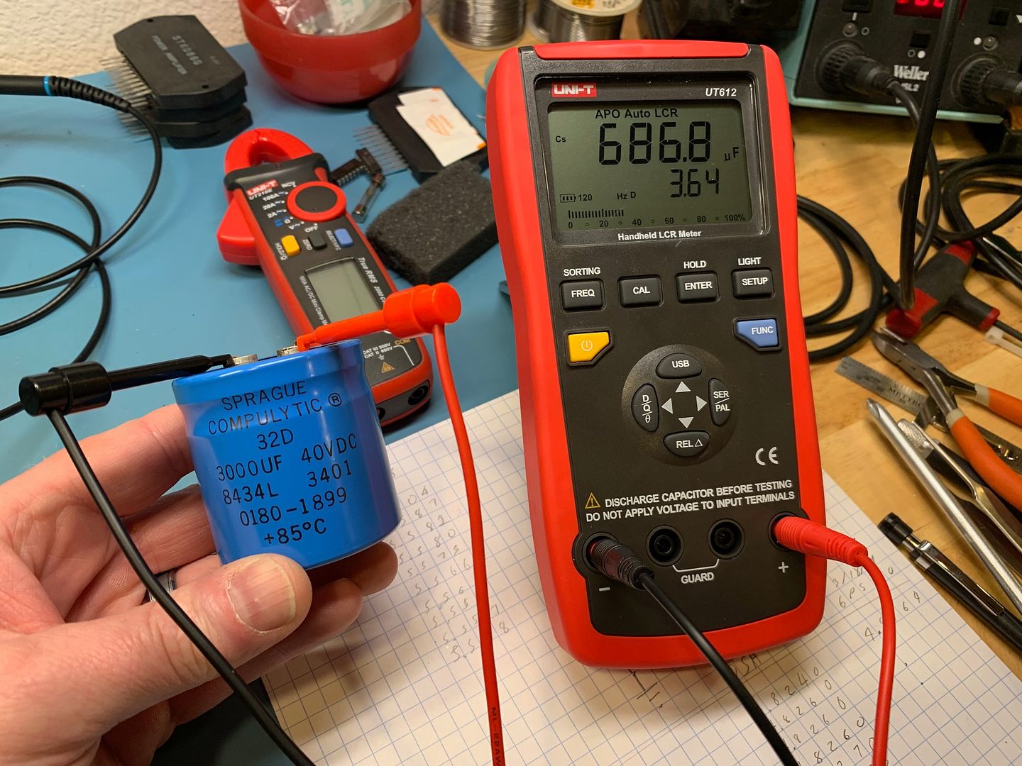
In my recent HP 6227B acquisition I found most of the electrolytics were bad or at best degraded. The 3000uF 40v C6 & C7 on both the main and slave board were bad. The 5uF 50v C2 on both the main and slave boards, bad. The 325uF 35v C9 & C9A on the motherboard were slightly degraded as well as the 1500uF 40v C1's. I'm just going to replace all of the electrolytics. The Mylar and ceramics are fine.
Even with all the degraded and bad caps the power supply still worked very well until the current draw or voltage was raised beyond a certain point. The 120Hz ripple got a bit ugly near max output.
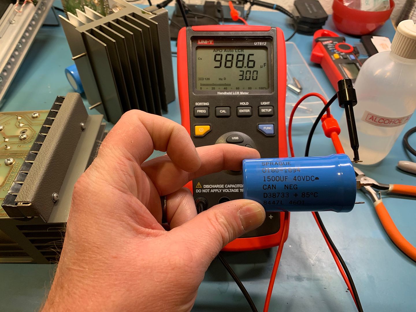
C1, I found NOS 1500uF 40v Sprague on eBay, they tested perfectly on my LCR meter when they arrived, both at 1560uF with very little leakage. Staying original as these are 5 pin snap-ins for mechanical stability. A radial cap could be used here, only two pins are being used on the board.
C2, replacing with 4.7uF 63v
https://www.mouser.com/ProductDetail/75-516D475M063JL6AE3C6 & C7, replacing with 12000uF 50v of the exact same physical size
https://www.mouser.com/ProductDetail/661-E36D500N123TC54MThese are a bit larger but not by so much it will cause inrush concerns, the larger caps here will only do good things.
C9 & C9A replacing with 470uF 63v
https://www.mouser.com/ProductDetail/75-516D477M063PS6AE3This is a DC filter cap for the crowbar supply, a bit larger will not hurt anything here.
C10 & C10A, replacing with 180uF 100v with the correct 5mm lead width
https://www.mouser.com/ProductDetail/661-EKYA101E181MK20SDC filter cap for the reference regulator supply, a bit larger here is good.
C11, replacing with 4.7uF 63v
https://www.mouser.com/ProductDetail/594-2222-021-28478C13, replacing with 22uF 63v
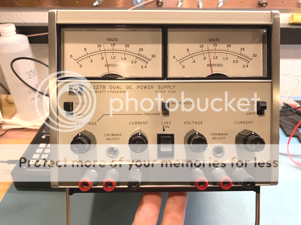
https://www.mouser.com/ProductDetail/75-516D226M063LL6AE3Mine starts with serial # 2451A, all the caps have date codes from 1984, but I suspect it was made a bit later than that due to the rocker style power switch, however mine still has the course and fine pots, not the 10 turn pots the OP's has. Sparky, what is your serial number?
Bad main filter caps;
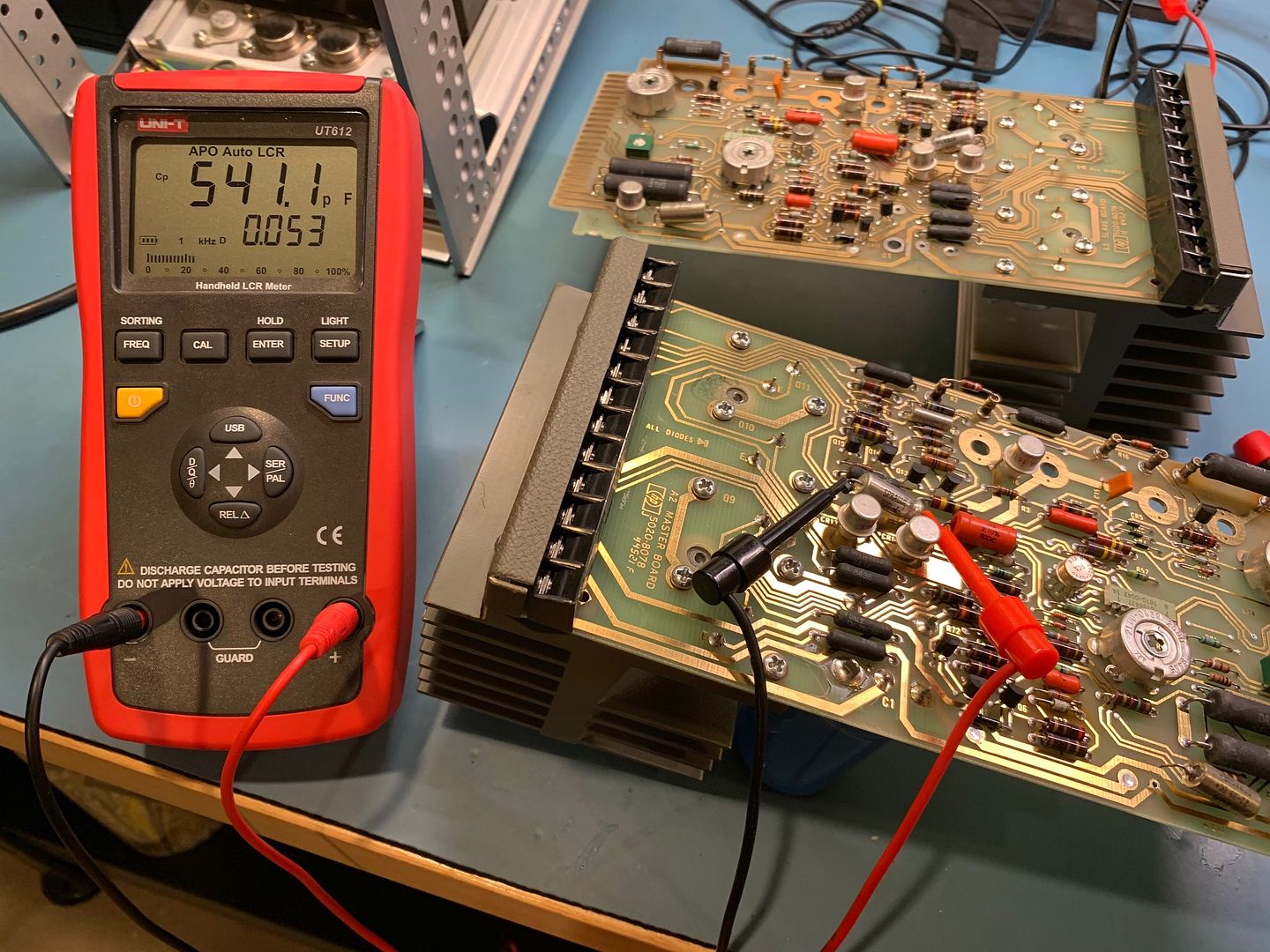
The main and slave boards slide out the back with ease;
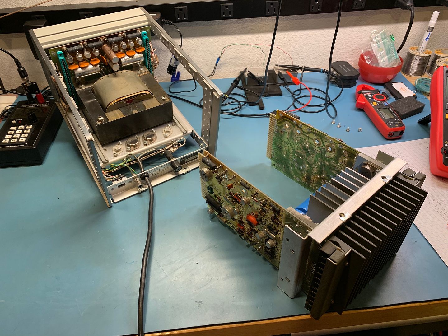
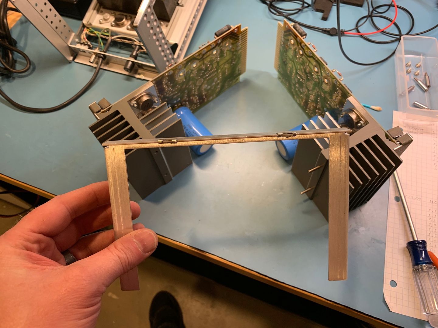
Then split in two;
Marginal C1 caps, replaced with NOS;
Slightly degraded crowbar supply C9;

The dead C2;
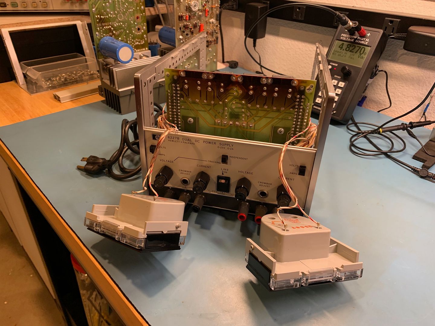
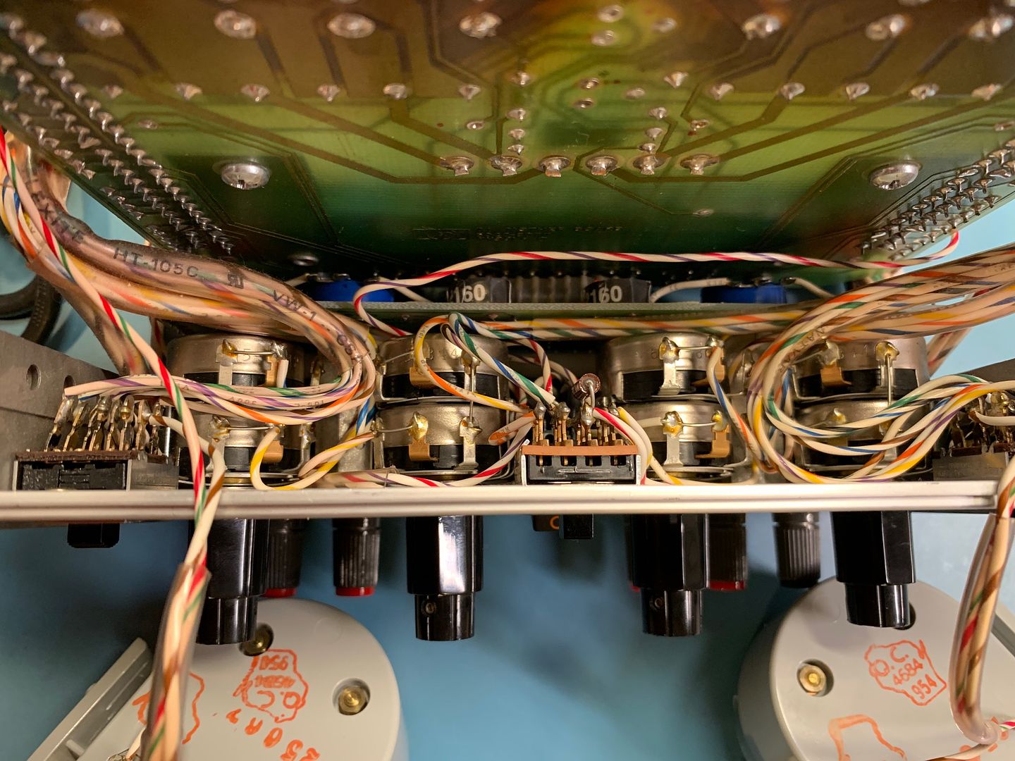
Getting to the caps on the Motherboard;
The parts will be here later this week. Ugh!... the wait.


