Author Topic: HV PSU resto, metal rectifiers  (Read 17579 times)

0 Members and 1 Guest are viewing this topic.

Offline GKTopic starter

  • Super Contributor
  • ***
  • Posts: 2607
  • Country: au
HV PSU resto, metal rectifiers
« on: February 27, 2015, 08:24:18 am »
I'm restoring three variable, electronically regulated HV power supplies: A Siemens/Ediswan Model R1103A and a pair of Marconi model TF1109A's. The units are almost identical, the Siemens/Ediswan version differing mostly in chassis layout, and has an updated circuit having a separate rectified and filtered screen supply for the series-pass tubes, whereas in the Marconi version the tubes (12E1's) are just connected as triodes. 

I'm ditching all of the original capacitors and the carbon resistors will be replaced as well. Most of the resistors measure quite a bit (higher) out of tolerance, as old carbon resistors a prone to do.

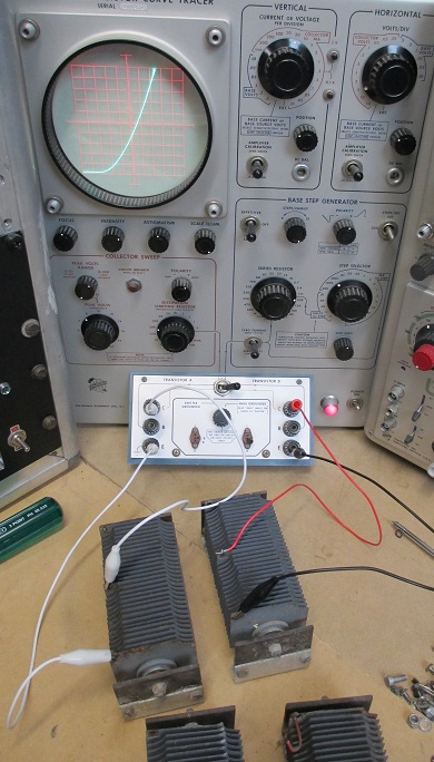
With the goal of long-term reliability, I was originally planning to ditch the metal/selenium rectifiers for modern silicon, but after checking them out on my Tek 575 curve tracer and finding them operationally fine, I've decided to keep them just for the original and "cool" factor. The main, unregulated HT rail is full-wave bridge rectified by a pair of these diode stacks. Each stack is has an electrical connection to the central plate/cooling fin, so they are essentially "wired" as two series connected diodes per stack. The central connections of a pair go to the transformer secondary. I've tested each diode connection of each stack individually and they all measure very consistently the same, dropping approximately 35V at a forward current of 200mA and having no reverse current of consequence.

The rectifiers need a good clean/paint strip and repaint after rust conversion. I was about to start by just dunking these in solvent, but I'm not so sure. I know that the selenium in these things is deposited on the stacked coins in a very thin layer but I have no idea just how fragile/susceptible these things are to mechanical handling and dipping in solvent. Does anyone out there have have any idea?


This metal rectifier was once a home for wasps:


On the curve tracer:


The Siemens / Ediswan incarnation:


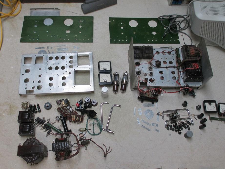
The two Marconi units almost stripped:


Capacitors for the bin:

« Last Edit: February 27, 2015, 08:41:31 am by GK »
Bzzzzt. No longer care, over this forum shit.........ZZzzzzzzzzzzzzzzz
 

Offline T3sl4co1l

  • Super Contributor
  • ***
  • Posts: 21651
  • Country: us
  • Expert, Analog Electronics, PCB Layout, EMC
    • Seven Transistor Labs
Re: HV PSU resto, metal rectifiers
« Reply #1 on: February 27, 2015, 12:52:27 pm »
I bet those capacitors are full of healthy stuff... :o

Tim
Seven Transistor Labs, LLC
Electronic design, from concept to prototype.
Bringing a project to life?  Send me a message!
 

Offline amyk

  • Super Contributor
  • ***
  • Posts: 8258
Re: HV PSU resto, metal rectifiers
« Reply #2 on: February 27, 2015, 01:50:19 pm »
The Nitrogol caps don't contain any PCBs, despite the scary-sounding name.

P.S. you might be able to sell them, it seems there's a market for audiophiles(fools?) buying "vintage" capacitors.
 

Offline JacquesBBB

  • Frequent Contributor
  • **
  • Posts: 829
  • Country: fr
Re: HV PSU resto, metal rectifiers
« Reply #3 on: February 27, 2015, 02:18:30 pm »
Is it always necessary to ditch these high voltage capacitors ?

I have  two HV tube power supply that  are waiting in my workshop for some
time on my side to rejuvenate them.

One is a 300V power supply.
I already checked some of these capacitors (10uF, 550V electrolytic or  2.2uF 630 V paper), and they had (from memory)
relatively good properties :  cap value close to original, and  relatively low ESR.

The other one is a 3kV PSU (Fluke 415b)  with  2uF 3kV oil caps that are not that easy/cheap  to find.
Somewhat similar ones can be found
(277$ each (by 8 ) at Mouser) (see attached pict)
« Last Edit: February 27, 2015, 03:59:12 pm by JacquesBBB »
 

Offline T3sl4co1l

  • Super Contributor
  • ***
  • Posts: 21651
  • Country: us
  • Expert, Analog Electronics, PCB Layout, EMC
    • Seven Transistor Labs
Re: HV PSU resto, metal rectifiers
« Reply #4 on: February 27, 2015, 04:12:20 pm »
The main problems are, if they are leaky (moisture ingress?) or leaky (oozing PCBs), they should be disposed of appropriately.

If they're actually PCB free, and not leaking, heck, they're probably fine, leave 'em in for another 50 years!

Tim
Seven Transistor Labs, LLC
Electronic design, from concept to prototype.
Bringing a project to life?  Send me a message!
 

Offline JacquesBBB

  • Frequent Contributor
  • **
  • Posts: 829
  • Country: fr
Re: HV PSU resto, metal rectifiers
« Reply #5 on: February 27, 2015, 04:18:09 pm »
Not leaking,  but probably not PCB  free.
 

Offline SeanB

  • Super Contributor
  • ***
  • Posts: 16276
  • Country: za
Re: HV PSU resto, metal rectifiers
« Reply #6 on: February 27, 2015, 05:21:04 pm »
Do not dip those rectifiers in anything, just use a brush and get the dust off. Paint solvents will penetrate the existing paint ( likely a duco with the age of them) and will very quickly give out that magic incredibly bad smelling smell that you will instantly know is a dying selenium rectifier. the only protection is to use a small brush and grey paint on the fins, not getting anywhere near the middle if you want, but they work fine with a slight rust on the fins.

As to the HV blocks, as long as the glass seals are intact use them, if they start to leak or weep replace. They are very rare that they fail and generally last till the case rots through underneath. With the construction being basically oil soaked paper and thick foil the replacements will not last, as they are wound with thinner insulation and close to transparent foils.

If you do replace the stack rectifiers keep the originals in place and wire the replacement microwave oven diodes and series resistors up under the chassis, so it still looks original from the top.
 

Offline GKTopic starter

  • Super Contributor
  • ***
  • Posts: 2607
  • Country: au
Re: HV PSU resto, metal rectifiers
« Reply #7 on: February 28, 2015, 12:28:58 am »
I have a boot full of these old paper capacitors from various pieces of equipment and I am disposing of all of them. I've had more than one leakage incident (from otherwise perfect looking caps) and I just don't want that crap and potential bother in my shack anymore. Whats worse is that these caps when chassis mounted are typically mounted facing down (as they are in the Marconi supplies) , so when the glass/ceramic seals finally give out you have oil of unknown composition dribbling down the inside of your equipment rack onto and through the instruments beneath.

The rectifiers look a lot better in the photos than they do in real life. The paint is flaking quite badly and on one the rust is particularly severe on the underside. They need at minimum a mechanical clean and a dip or brushing in rust converter before repaint. I'll avoid the use of solvent.
 
« Last Edit: March 01, 2015, 11:47:05 am by GK »
Bzzzzt. No longer care, over this forum shit.........ZZzzzzzzzzzzzzzzz
 

Offline TSL

  • Regular Contributor
  • *
  • Posts: 243
  • Country: au
Re: HV PSU resto, metal rectifiers
« Reply #8 on: February 28, 2015, 02:54:59 am »
I've see restorations where caps like those have been carefully disassembled, contents discarded, and a new cap placed inside the metal container so the build still has the same "look"

cheers

Tim
VK2XAX :: QF56if :: BMARC :: WIA :: AMSATVK
 

Offline c4757p

  • Super Contributor
  • ***
  • Posts: 7799
  • Country: us
  • adieu
Re: HV PSU resto, metal rectifiers
« Reply #9 on: February 28, 2015, 03:05:31 am »
I've see restorations where caps like those have been carefully disassembled, contents discarded, and a new cap placed inside the metal container so the build still has the same "look"

I hate this so much.
No longer active here - try the IRC channel if you just can't be without me :)
 

Offline GKTopic starter

  • Super Contributor
  • ***
  • Posts: 2607
  • Country: au
Re: HV PSU resto, metal rectifiers
« Reply #10 on: February 28, 2015, 09:13:08 am »
I ended up cleaning the rectifiers in a methylated spirit bath. A wire brush with bristles long enough to reach down to the center was used to scrape away all of the paint that was flaking. Then another dip in the metho, a thorough blast with compressed air and then a dip in rust converter. A couple of hours later once the rust converter had done its job, turning the surface rust into a tough, paintable black oxide, the rectifiers were given a final going over with the wire bush, a final metho bath for a clean and then a spray of flat black engine enamel (what I had on the shelf).

Here is one of the rectifiers just after rust conversion:


Fresh after applying the final coat of paint:


The chassis' of these Marconi supplies are raw, non-anodized aluminum. You can polish such as chassis up and it'll look all nice and pretty immediately after, but in the long term it will always develop an unsightly oxide layer and especially so in an open chassis design such as this, in which dust inevitably harboring a degree of moisture from the air will settle on the chassis. So I painted them with an automotive engine enamel formulated for cast aluminum. Tomorrow I'll bake them in my oven at 90 deg. C for an hour each.


The front panel for one of these Marconi supplies had a pair of additional holes drilled for some kind of modification at some time in its life. The holes were filled with an epoxy putty by Selleys called "Knead It". One hardened it was sanded back flat with 240 grit sandpaper.


You often find some interesting things restoring old stuff, like this for instance. One of the big 1000V 8uF oil-filled caps was originally clamped down on top of one of the wiring looms. The insulation of the wires were actually cut right through to the copper, but the layer of paint on the capacitor housing must have been a sufficient insulator because the power supply was operational in this state for decades.


« Last Edit: March 01, 2015, 11:46:46 am by GK »
Bzzzzt. No longer care, over this forum shit.........ZZzzzzzzzzzzzzzzz
 

Offline GKTopic starter

  • Super Contributor
  • ***
  • Posts: 2607
  • Country: au
Re: HV PSU resto, metal rectifiers
« Reply #11 on: February 28, 2015, 09:32:07 am »
I've see restorations where caps like those have been carefully disassembled, contents discarded, and a new cap placed inside the metal container so the build still has the same "look"


I've done this myself in pieces of equipment of particular value, such as my WWII transceivers and transmitters, which are, essentially, functional museum pieces. Despite the drool it seems it incite in some it's a perfectly legitimate part of making operational a piece of kit that would otherwise be devalued if it was unduly modified from standard form.

As for these HV power supplies, I don't really care about originality as they have minimal value and unrepaired would be just destined for the tip. I'm mostly just interested in getting a trio of operational and useful HV power supplies going for my workbench. Though there is of course still the "coolness" factor of making reliable and pressing into service kit with pretty glowing valves.
« Last Edit: February 28, 2015, 09:39:17 am by GK »
Bzzzzt. No longer care, over this forum shit.........ZZzzzzzzzzzzzzzzz
 

Offline GKTopic starter

  • Super Contributor
  • ***
  • Posts: 2607
  • Country: au
Re: HV PSU resto, metal rectifiers
« Reply #12 on: February 28, 2015, 09:54:12 am »
The Nitrogol caps don't contain any PCBs, despite the scary-sounding name.


Hmm... The others are TCC brand "Visconol". Any idea about those?
Bzzzzt. No longer care, over this forum shit.........ZZzzzzzzzzzzzzzzz
 

Offline GKTopic starter

  • Super Contributor
  • ***
  • Posts: 2607
  • Country: au
Re: HV PSU resto, metal rectifiers
« Reply #13 on: February 28, 2015, 11:53:12 am »
Back on the curve tracer and all is hunky-dory.

Bzzzzt. No longer care, over this forum shit.........ZZzzzzzzzzzzzzzzz
 

Offline T3sl4co1l

  • Super Contributor
  • ***
  • Posts: 21651
  • Country: us
  • Expert, Analog Electronics, PCB Layout, EMC
    • Seven Transistor Labs
Re: HV PSU resto, metal rectifiers
« Reply #14 on: February 28, 2015, 02:50:02 pm »
Black selenium rectifiers, sexy 8)

If you wanted to preserve the shine-able chassis, anodize would leave a dull but robust finish; you'd need a clear coat to really keep it shiny.

Probably not really robust for something like this, and anyway, it's an ugly bit of rackmount kit, drab military-industrial colors are perfect. ;)

Tim
Seven Transistor Labs, LLC
Electronic design, from concept to prototype.
Bringing a project to life?  Send me a message!
 
The following users thanked this post: 001

Offline amyk

  • Super Contributor
  • ***
  • Posts: 8258
Re: HV PSU resto, metal rectifiers
« Reply #15 on: February 28, 2015, 04:15:05 pm »
The Nitrogol caps don't contain any PCBs, despite the scary-sounding name.


Hmm... The others are TCC brand "Visconol". Any idea about those?
According to this:
http://www.scew.gov.au/sites/www.scew.gov.au/files/resources/378b7018-8f2a-8174-3928-2056b44bf9b0/files/anzecc-gl-identification-pcb-containing-capacitors-information-booklet-electricians-and-electrical.pdf

TCC Visconol shouldn't have PCBs, but TCC also produced caps with PCBs, so look at the model number.
 

Offline GKTopic starter

  • Super Contributor
  • ***
  • Posts: 2607
  • Country: au
Re: HV PSU resto, metal rectifiers
« Reply #16 on: March 01, 2015, 11:38:06 am »
Probably not really robust for something like this, and anyway, it's an ugly bit of rackmount kit, drab military-industrial colors are perfect. ;)


I have an assortment of left over paints from a prior project.


« Last Edit: March 01, 2015, 11:46:21 am by GK »
Bzzzzt. No longer care, over this forum shit.........ZZzzzzzzzzzzzzzzz
 
The following users thanked this post: 001

Offline GKTopic starter

  • Super Contributor
  • ***
  • Posts: 2607
  • Country: au
Re: HV PSU resto, metal rectifiers
« Reply #17 on: March 01, 2015, 11:41:58 am »
Getting closer......

Bzzzzt. No longer care, over this forum shit.........ZZzzzzzzzzzzzzzzz
 

Offline GKTopic starter

  • Super Contributor
  • ***
  • Posts: 2607
  • Country: au
Re: HV PSU resto, metal rectifiers
« Reply #18 on: March 01, 2015, 11:51:10 am »
The Nitrogol caps don't contain any PCBs, despite the scary-sounding name.


Hmm... The others are TCC brand "Visconol". Any idea about those?
According to this:
http://www.scew.gov.au/sites/www.scew.gov.au/files/resources/378b7018-8f2a-8174-3928-2056b44bf9b0/files/anzecc-gl-identification-pcb-containing-capacitors-information-booklet-electricians-and-electrical.pdf

TCC Visconol shouldn't have PCBs, but TCC also produced caps with PCBs, so look at the model number.


lol, thanks for the reminder. I have that document somewhere (one of the gazillion pdf's stored on my hard disk) but had forgotten all about it.
Bzzzzt. No longer care, over this forum shit.........ZZzzzzzzzzzzzzzzz
 

Offline T3sl4co1l

  • Super Contributor
  • ***
  • Posts: 21651
  • Country: us
  • Expert, Analog Electronics, PCB Layout, EMC
    • Seven Transistor Labs
Re: HV PSU resto, metal rectifiers
« Reply #19 on: March 01, 2015, 04:36:45 pm »
Probably not really robust for something like this, and anyway, it's an ugly bit of rackmount kit, drab military-industrial colors are perfect. ;)


I have an assortment of left over paints from a prior project.

Well damn, I sure called that one :-DD

About as pretty as olive-drab can be :-+ :-+
Seven Transistor Labs, LLC
Electronic design, from concept to prototype.
Bringing a project to life?  Send me a message!
 

Offline SeanB

  • Super Contributor
  • ***
  • Posts: 16276
  • Country: za
Re: HV PSU resto, metal rectifiers
« Reply #20 on: March 01, 2015, 05:24:00 pm »
Olive drab never shined that good, I used to paint it in pretty patterns, mixing the olive drab, light earth and dark earth along with flat black as patterning. Then I moved, and it was all grey and sky blue. i did change the inner part colours I used though, from matt black to satin black, it was just as dark but looked ( and wore better) almost the same.
 

Offline tautech

  • Super Contributor
  • ***
  • Posts: 28308
  • Country: nz
  • Taupaki Technologies Ltd. Siglent Distributor NZ.
    • Taupaki Technologies Ltd.
Re: HV PSU resto, metal rectifiers
« Reply #21 on: March 01, 2015, 07:10:45 pm »
Probably not really robust for something like this, and anyway, it's an ugly bit of rackmount kit, drab military-industrial colors are perfect. ;)

I have an assortment of left over paints from a prior project.

Series 2 landy if i'm not mistaken?

Chuck a 186 holden and Rover 90 Diff heads in it.  :-+

Your workshops tooooooo big.  :rant:
Avid Rabid Hobbyist
Siglent Youtube channel: https://www.youtube.com/@SiglentVideo/videos
 

Offline SeanB

  • Super Contributor
  • ***
  • Posts: 16276
  • Country: za
Re: HV PSU resto, metal rectifiers
« Reply #22 on: March 01, 2015, 08:38:36 pm »
Did you fix all the oil leaks, or did it all run out.
 

Offline GKTopic starter

  • Super Contributor
  • ***
  • Posts: 2607
  • Country: au
Re: HV PSU resto, metal rectifiers
« Reply #23 on: March 02, 2015, 07:43:34 am »
SIIA 109" with Aust. Army-modified front guards.

I think the original 2.25L is a better motor than the Holden 6. I fully reconditioned mine and it is purring like a kitten. Though someone for who knows what reason molested mine by fitting a crappy Holden 6 Stromberg carburetor. I ditched that and rebuilt an original Solex (a much better unit) from several defunct donors.

Did you fix all the oil leaks,

Yes.

Bzzzzt. No longer care, over this forum shit.........ZZzzzzzzzzzzzzzzz
 

Offline tautech

  • Super Contributor
  • ***
  • Posts: 28308
  • Country: nz
  • Taupaki Technologies Ltd. Siglent Distributor NZ.
    • Taupaki Technologies Ltd.
Re: HV PSU resto, metal rectifiers
« Reply #24 on: March 02, 2015, 08:41:38 am »
SIIA 109" with Aust. Army-modified front guards.

I think the original 2.25L is a better motor than the Holden 6. I fully reconditioned mine and it is purring like a kitten. Though someone for who knows what reason molested mine by fitting a crappy Holden 6 Stromberg carburetor. I ditched that and rebuilt an original Solex (a much better unit) from several defunct donors.
I had a SIII with Rover 90 DH's, IIA box & TC with OD behind a Yellow Terror Hi-Torque Head 186 STD manifolds & carbie.
Reasonably happy @100 Km/h but at 90 would do mid to high 20's MPG.

The 2 1/4 L Rovers would run nice but nowhere near the torque or power of the 186.
And they only had a 3 bearing crank.  :palm:

Your's being ex-military would probably have dual tanks and the heavier springs?
Avid Rabid Hobbyist
Siglent Youtube channel: https://www.youtube.com/@SiglentVideo/videos
 

Offline GKTopic starter

  • Super Contributor
  • ***
  • Posts: 2607
  • Country: au
Re: HV PSU resto, metal rectifiers
« Reply #25 on: March 02, 2015, 09:25:15 am »
Yes, the crank is only 3 main bearings but it is heavily over-engineered and the bearing journals are huge. The little 2.25L has a solid roller camshaft (and advance never seen on a Holden 6) and delivers a good spread of torque and peak power for its capacity and vintage. It was rated at 70bhp D.I.N at only 4000 rpm. That is a genuine, installed, at-the-flywheel figure. Like many other manufacturers Holden specified their engines (before the compliance laws and regulations were tightened up) bhp S.A.E. which was often inflated by anything up to 30%. The 186 (3L) from memory was specified at ~120 bhp, but 80 bhp is a more realistic figure.
Really, the bigger 186 was only marginally more powerful than the 2.25L and it had to be revved just as hard (if not a little more) to deliver. A modified 186 would be a different story though. They were a popular swap for a clapped out 2.25L back in the day down here simply because they were common as dirt and cheap.
 
My Land Rover isn't ex-army, I just fitted the guards because my originals were battered beyond worthwhile repair and I got the army guards for a good deal.
« Last Edit: March 02, 2015, 09:29:42 am by GK »
Bzzzzt. No longer care, over this forum shit.........ZZzzzzzzzzzzzzzzz
 

Offline tautech

  • Super Contributor
  • ***
  • Posts: 28308
  • Country: nz
  • Taupaki Technologies Ltd. Siglent Distributor NZ.
    • Taupaki Technologies Ltd.
Re: HV PSU resto, metal rectifiers
« Reply #26 on: March 02, 2015, 10:37:57 am »
Yes, the crank is only 3 main bearings but it is heavily over-engineered and the bearing journals are huge.
Yep, they even used the same crank & block for the diesel engine, but it IIRC was only ~65 hp, but you wouldn't want to mod that for more hp with only 3 journals.
Avid Rabid Hobbyist
Siglent Youtube channel: https://www.youtube.com/@SiglentVideo/videos
 

Offline GKTopic starter

  • Super Contributor
  • ***
  • Posts: 2607
  • Country: au
Re: HV PSU resto, metal rectifiers
« Reply #27 on: March 02, 2015, 12:42:58 pm »
Okayyyyyy............. back on topic. This PSU restoration project actually began over 15 years ago when I was still living at home with my parents. That is when I acquired the first of the Marconi units. I didn't have a manual for it then and I still can't locate one on the web, so I had to reverse engineer it as I pulled it apart. After pulling it apart I confirmed that I reverse engineered it correctly by rebuilding it on a plank of wood on my bedroom floor. My original notes:


The supplies parts were then boxed up and that is how they stayed until just recently! For my own records, I am now in the middle of redoing my circuit diagrams. Here is the bulk of the circuitry for the Marconi chassis:


I initially thought that the voltage feedback arrangement was a little odd, but once I studied the circuit a little more I realized that it is actually quite a clever circuit. The current for the VR tube (V3) is sourced from the clean, regulated side of the supply, but irrespective of the setting of the regulated output voltage, the current through the VR tube is essentially held constant.

V4 and V5 form a long-tail pair error amplifier. The output voltage stabilizes when the grid of V5 is at the ~same potential as the grid of V4 (which is at the fixed 85V reference potential derived from the VR tube). For the grid of V5 to reach 85V, the screen of V5 is maintained (regulated) at a little under 200V due to the voltage divider formed by R17 and R12. So a constant current of ~ [(200V-85V) / (R18+R19)] flows through the VR tube. This constant current is sourced from the regulated output via the H.T. Volts setting pot and associated range-switched resistors. So the output voltage is simply ~200V + the constant current times the variable voltage setting resistance. C3 is a Miller feedback compensation capacitor that incorporates the series pass tubes. C6 bootstraps the resistive anode load supply for V5, making it approximate a constant current source at frequencies somewhat above DC.


« Last Edit: March 02, 2015, 12:55:31 pm by GK »
Bzzzzt. No longer care, over this forum shit.........ZZzzzzzzzzzzzzzzz
 

Offline GKTopic starter

  • Super Contributor
  • ***
  • Posts: 2607
  • Country: au
Re: HV PSU resto, metal rectifiers
« Reply #28 on: March 21, 2015, 06:06:57 am »
The other one is a 3kV PSU (Fluke 415b)  with  2uF 3kV oil caps that are not that easy/cheap  to find.
Somewhat similar ones can be found
(277$ each (by 8 ) at Mouser) (see attached pict)


I can't think of many situations where I would seek out an expensive new oil cap to replace an old oil cap. High voltage film or electrolytic capacitors in series if necessary with parallel voltage-balancing resistors are the most practical way to go. In this case I didn't need to resort to series-connected caps. I replaced the 8uF/1000V oil caps with relatively inexpensive (~$14 each) 8uF/1100V film caps that were readily available.     


« Last Edit: March 21, 2015, 06:10:14 am by GK »
Bzzzzt. No longer care, over this forum shit.........ZZzzzzzzzzzzzzzzz
 

Offline GKTopic starter

  • Super Contributor
  • ***
  • Posts: 2607
  • Country: au
Re: HV PSU resto, metal rectifiers
« Reply #29 on: March 23, 2015, 09:06:43 am »
One of the chokes for one of the Marconi supplies unfortunately pooped itself, shorting the +843V unregulated supply rail to chassis. All was fine until I powered it up again with my CRO lead ground clip connected to the circuit ground then sitting at-843V. The inductor sizzled for a second and then the mains fuse went.

Does anyone know what kind of varnish these things are potted in? Is it shellac? I've had it sitting in acetone for while but so far it looks like it will need to soak for a week before I can extract the individual lamination's.
 
« Last Edit: March 23, 2015, 09:11:03 am by GK »
Bzzzzt. No longer care, over this forum shit.........ZZzzzzzzzzzzzzzzz
 

Offline T3sl4co1l

  • Super Contributor
  • ***
  • Posts: 21651
  • Country: us
  • Expert, Analog Electronics, PCB Layout, EMC
    • Seven Transistor Labs
Re: HV PSU resto, metal rectifiers
« Reply #30 on: March 23, 2015, 01:10:41 pm »
If it is shellac, it should dissolve in ethanol I think... should think acetone as well.  Don't know that shellac has ever been used in such thick layers, though?

I would suspect varnish, but if that's what it is, you aren't getting it off with simple solvents.  Suggest fire?

Curious that it seems to be flaking away.

I'd suggest methylene chloride, but if you were hoping to reuse some of the wire, that wouldn't work out so well... :P

Tim
Seven Transistor Labs, LLC
Electronic design, from concept to prototype.
Bringing a project to life?  Send me a message!
 

Offline SeanB

  • Super Contributor
  • ***
  • Posts: 16276
  • Country: za
Re: HV PSU resto, metal rectifiers
« Reply #31 on: March 23, 2015, 06:18:03 pm »
That would be a dipped shellac, which is pretty much going to ignore acetone. Dissolves in methanol quite nicely, and as you are going to be making a new pressboard former for it in any case I would suggest a very simple method, which is place it in a small tin box and make a fire with it inside for about 5 hours. Then open the tin after it is cool, and dunk the charred mess in methanol overnight, then wire brush the char off till you can undo the bolts, then take it apart.

The paper insulation has gotten moisture in it, and then carbonised to create the ground short. Use high temperature wire on the new one, and at least 5 layers of kapton tape between the first winding and the paper former, then a single layer of the kapton tape per layer. First turn use a PTFE sleeve for extra insulation, as it likely arced there first. Bonus is that it will be a lot less bulky with the kapton tape, and the number of windings is not as critical, provided you fill most of the core. Just note where the air gaps are and put back the same way. You can varnish it after winding, but with modern tape and wire it will not be needed.

The common field fix for these shorted chokes was simply to undo the 4 bolts and place the whole choke on 4 20mm long plastic spacers so that the live case would not touch ground. Works, but the choke case is then part of the B+ circuit and is at high voltage.
« Last Edit: March 23, 2015, 06:20:12 pm by SeanB »
 

Offline T3sl4co1l

  • Super Contributor
  • ***
  • Posts: 21651
  • Country: us
  • Expert, Analog Electronics, PCB Layout, EMC
    • Seven Transistor Labs
Re: HV PSU resto, metal rectifiers
« Reply #32 on: March 23, 2015, 07:49:30 pm »
If you knew which end is shorted to ground, you could possibly move it to the ground side of the rectifier / transformer CT! :P  I forget offhand if that's even possible in the circuit...

Tim
Seven Transistor Labs, LLC
Electronic design, from concept to prototype.
Bringing a project to life?  Send me a message!
 

Offline SeanB

  • Super Contributor
  • ***
  • Posts: 16276
  • Country: za
Re: HV PSU resto, metal rectifiers
« Reply #33 on: March 23, 2015, 07:57:12 pm »
It is a HT choke, only one winding and 2 connections. Part of a LC filter on the HT supply.
 

Offline GKTopic starter

  • Super Contributor
  • ***
  • Posts: 2607
  • Country: au
Re: HV PSU resto, metal rectifiers
« Reply #34 on: March 24, 2015, 09:04:35 am »
Actually the acetone appears to be working its magic - it just takes time. 24 Hours later and I can see bare lamination's. The acetone I had it sitting in has evaporated but I now have the choke fully submerged in an enclosed container. I'll just let it soak for a couple of nights and see what happens.

« Last Edit: March 24, 2015, 09:08:42 am by GK »
Bzzzzt. No longer care, over this forum shit.........ZZzzzzzzzzzzzzzzz
 

Offline GKTopic starter

  • Super Contributor
  • ***
  • Posts: 2607
  • Country: au
Re: HV PSU resto, metal rectifiers
« Reply #35 on: March 28, 2015, 09:17:41 am »
The acetone soak did the job, dissolving the shellac (I presume that is what it was). There was no saving the original bobbin, however. I had to hacksaw through the windings and then pull them out with vise grips with the core gripped in the bench vice. The core was gaped with a sheet of that phenolic-like stuff that the bobbin is made of. I think I'll make a replacement bobbin with rectangles of etched FR4 bonded with Araldite.
Bzzzzt. No longer care, over this forum shit.........ZZzzzzzzzzzzzzzzz
 

Offline SeanB

  • Super Contributor
  • ***
  • Posts: 16276
  • Country: za
Re: HV PSU resto, metal rectifiers
« Reply #36 on: March 28, 2015, 09:55:31 am »
Make extended end cheeks for the bobbin, so that the leadout wire does not come into contact with the core lessening the insulation requirements. Lots of tape as well for the rewind, and at least for a choke you do not need an exact number of turns, just enough to mostly fill the winding area, then a generous layer of tape to cover and then an overcoat of varnish.
 

Offline GKTopic starter

  • Super Contributor
  • ***
  • Posts: 2607
  • Country: au
Re: HV PSU resto, metal rectifiers
« Reply #37 on: March 29, 2015, 09:36:48 am »
Yeah, I'll certainly make some end plates to the bobbin. That will also make it ten times easier to wind.
Bzzzzt. No longer care, over this forum shit.........ZZzzzzzzzzzzzzzzz
 

Offline SeanB

  • Super Contributor
  • ***
  • Posts: 16276
  • Country: za
Re: HV PSU resto, metal rectifiers
« Reply #38 on: March 29, 2015, 09:49:49 am »
Yeah, I'll certainly make some end plates to the bobbin. That will also make it ten times easier to wind.

Make it a coreless self supporting pancake winding, without anything other than varnish holding the windings together. That will be a challenge.  >:D
 

Offline Richard Head

  • Frequent Contributor
  • **
  • Posts: 685
  • Country: 00
Re: HV PSU resto, metal rectifiers
« Reply #39 on: March 30, 2015, 05:39:07 am »
I wonder if you were able to count the number of turns? I suspect not looking at the windings!
 

Offline GKTopic starter

  • Super Contributor
  • ***
  • Posts: 2607
  • Country: au
Re: HV PSU resto, metal rectifiers
« Reply #40 on: March 30, 2015, 10:51:31 am »
It was impossible to unwrap the windings but fortunately the value of the inductance isn't critical at all so I'll just fill the winding window with the same gauge wire.
If I was paranoid I could wind a layer onto the new bobbin, assemble and then measure the inductance to compute the cores AL value. Then I could compute the number of turns for the original inductance.


Bzzzzt. No longer care, over this forum shit.........ZZzzzzzzzzzzzzzzz
 

Offline Richard Head

  • Frequent Contributor
  • **
  • Posts: 685
  • Country: 00
Re: HV PSU resto, metal rectifiers
« Reply #41 on: March 31, 2015, 07:36:27 pm »
If I was paranoid I could wind a layer onto the new bobbin, assemble and then measure the inductance to compute the cores AL value. Then I could compute the number of turns for the original inductance.
I would do that. If you put on too many turns you may well saturate the core.
 

Offline T3sl4co1l

  • Super Contributor
  • ***
  • Posts: 21651
  • Country: us
  • Expert, Analog Electronics, PCB Layout, EMC
    • Seven Transistor Labs
Re: HV PSU resto, metal rectifiers
« Reply #42 on: March 31, 2015, 07:43:35 pm »
DOIT! Swinging choke... ;)

Tim
Seven Transistor Labs, LLC
Electronic design, from concept to prototype.
Bringing a project to life?  Send me a message!
 

Offline GKTopic starter

  • Super Contributor
  • ***
  • Posts: 2607
  • Country: au
Re: HV PSU resto, metal rectifiers
« Reply #43 on: March 31, 2015, 11:04:18 pm »
I can't see myself getting substantially more turns onto the core than it originally had. That bobbin was packed so damn tight it's a miracle they managed to slide it onto the core.

Also, saturation is not an abrupt phenomenon in an inductor like this and a large value of variation in the inductance is easily tolerable. And in addition to that even if I did somehow wind up too many turns and have an excessive degree of saturation all I'd have to do is slightly increase the core gap. So then I'd have the original value of inductance but with a little higher DCR than original. That's not remotely critical either.
« Last Edit: May 09, 2015, 01:05:40 pm by GK »
Bzzzzt. No longer care, over this forum shit.........ZZzzzzzzzzzzzzzzz
 

Offline GKTopic starter

  • Super Contributor
  • ***
  • Posts: 2607
  • Country: au
Re: HV PSU resto, metal rectifiers
« Reply #44 on: May 09, 2015, 12:55:37 pm »
Well I haven't found the motivation to hand wind this inductor yet, but this afternoon I finally knocked off the one of the two Marconi supplies whose inductors are still OK. Here it is in all its glory. The scope screen shot shows the regulated output ripple and noise with the output voltage set to 400V and a load current of 130mA. Most of the HF component is courtesy of the local AM radio broadcast station.

This is a power supply that needs to be treated with respect. On the highest voltage range the potential at the "UNREG" binding post is in the vicinity of 800VDC.
You don't want to accidentally grab hold of that binding post instead of one of the 6.3VAC ones.


« Last Edit: May 09, 2015, 01:08:13 pm by GK »
Bzzzzt. No longer care, over this forum shit.........ZZzzzzzzzzzzzzzzz
 

Offline JacquesBBB

  • Frequent Contributor
  • **
  • Posts: 829
  • Country: fr
Re: HV PSU resto, metal rectifiers
« Reply #45 on: May 09, 2015, 01:54:06 pm »
Very impressive !!

You put the level quite high. I will certainly not try to reach this degree of perfection when I will try to restore my HV power supplies.
 

Offline GKTopic starter

  • Super Contributor
  • ***
  • Posts: 2607
  • Country: au
Re: HV PSU resto, metal rectifiers
« Reply #46 on: May 09, 2015, 11:20:42 pm »
Thanks, though I thought that my wiring was actually a little messy.  ;D

One thing that I knew about, but forgot when finishing this thing off (d'oh) is the supplies behavior when warming up and when switching ranges. The power output tubes warm up before the pentodes in the regulator circuit do. This causes the output V to over shoot / saturate towards the unregulated potential for few seconds until the pentodes come up to temperature. The same happens briefly when switching ranges, as the range switch that modifies the feedback resistance is not a make-before-break type. As a consequence feedback is temporarily lost when the switch wiper is in motion and the output voltmeter pegs briefly to the right.

The original electrolytic output capacitor had a marked rating of 450V "WKG" (working). The surge voltage capability must have been substantial however, as on the highest voltage range the unregulated potential is about 800V and the temporary spike in the output voltage is only limited by the saturated series resistance of the two 21E1 triode-connected series-pass power tetrodes in parallel.

A modern 450V rated electrolytic doesn't doesn't seem to fare too well in comparison, however. On my first range change it went out in spectacular fashion, filling my workshop with that stinky white smoke. For the output capacitor I ended up soldering two 450V electros in series with voltage balancing resistors.


« Last Edit: May 09, 2015, 11:24:59 pm by GK »
Bzzzzt. No longer care, over this forum shit.........ZZzzzzzzzzzzzzzzz
 

Offline SeanB

  • Super Contributor
  • ***
  • Posts: 16276
  • Country: za
Re: HV PSU resto, metal rectifiers
« Reply #47 on: May 10, 2015, 07:27:57 am »
I have some old tantalum capacitors with a working voltage of 35V, but they also are rated for a 70v surge. Others were rated for 40V but have a 130VDC surge rating.  Likely the old 450V unit would survive 700V with only an increased leakage, as the thicker foil and paper would survive the short overvoltage for a few seconds with only some extra oxide forming.


Share me

Digg  Facebook  SlashDot  Delicious  Technorati  Twitter  Google  Yahoo
Smf