Hi all,
First post here, I've messed around with a few bits of electronics before but would appreciate some advice on this. It's my mother's 3rd generation ipod nano, that won't accept charge any more. If you plug it in it charges for maybe a second or two, then says it's charged. As soon as you unplug it the state of charge is exactly where it started. I fitted a replacement battery which didn't change anything. If you charge a battery up externally and then fit it it works fine for the duration of the battery charge, but still will not recharge.
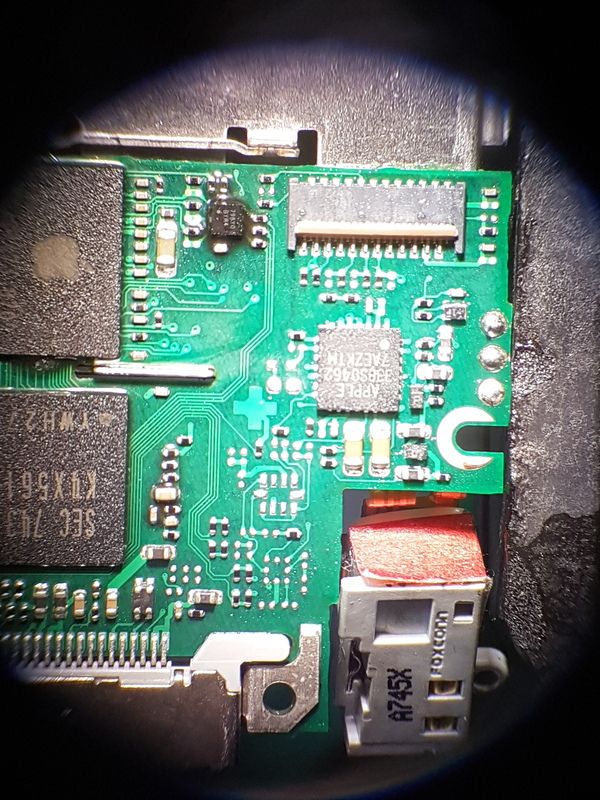
Sorry for the poor pictures, taken with my phone through a microscope. Those three contacts on the right are where the battery is connected. The third terminal I assume is a thermistor input - it measures ~10K to ground on the battery. I first thought that chip was the charge controller but it looks as though it's something to do with the LCD instead.
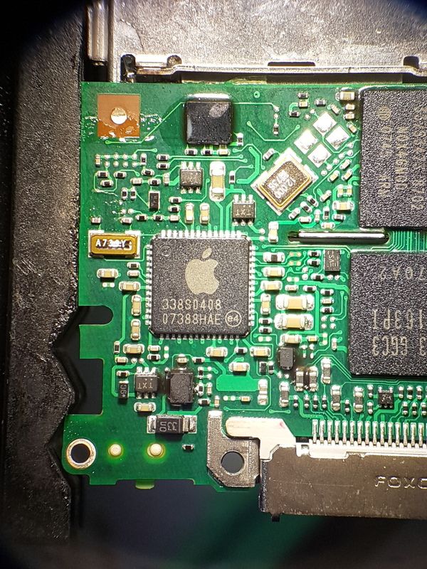
This chip (338S0408) seems the more likely candidate for the charge controller, with the battery fitted, charging cable connected and ipod running I can see the ~4.95 USB voltage on this chip, the battery voltage, as well as 3.3V, 3V, 2V, 1.8V and 1.2V. So I assume it does everything all in one chip, charge controller, and regulation for the different voltage rails?
This site mentions the power management IC as being the Dialog Semiconductor D1671B, although I can find no other information about it. The charge controller seems to be getting all the inputs it needs, and is happily powering the rest of the device so I don't know why it won't charge the battery. There's no obvious signs of damage that I can see, I've been over the solder joints and all seems good. Is it likely that the chip itself is bad, is it worth trying to get hold of another from dodgy suppliers on alibaba or something? Or is it more likely that some supporting component has died?
This site lists some other components related to the charging circuitry, NTLJF4156N, NTZS3151P, LM34919, LM34902. The NTZS3151Ps are the chips marked TXT in the picture above, and are small signal P channel mosfets which seem to be behaving. The NTLJF4156N is on the backside along with some passives:
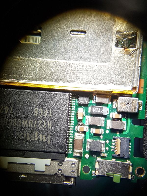
(top left of all the passives, next to the flash(?) memory)
with 4.3V on the drain and 0V on the gate. I'm wondering if this has something to do with the charging, 4.3 is pretty close to the 4.2 maximum battery voltage, maybe with diode drop or something? And it's the biggest FET there. Should I try applying a voltage to the gate to see if it's working? Or is it more likely to be whatever is meant to be sending the signal to the gate? It's very hard to trace connections on a multi layer board.

The other components have some gloop on them and are BGAs so hard to probe. The lm34902 is a 300mA current limiter, as it's a 450mAh battery I assume this must be for limiting the regulated outputs in case of a fault so nothing to do with the battery. The lm34919 is apparently a 600mA buck regulator, which is puzzling as it has an input voltage of 8V-40V, I haven't seen anything that high on this board, maybe to do with the LED back light driver or something?
Anyway, I'm not quite sure where best to go from here, does anyone have any experience of these sort of boards, common problems etc? Or generic approaches for diagnosing faulty components?
If all else fails, I have some tiny QFN lithium charge controller ICs left over from another project, is it likely to get terribly upset with me if I bodge one of those in in addition to all the other circuitry? I know it wouldn't get me back the charge level indications, but if it would at least let me charge it from USB again i would be happy...
Any advice greatly appreciated!
George


