Author Topic: LeCroy DDA-125 Stuck in standby (I think)  (Read 13714 times)

0 Members and 1 Guest are viewing this topic.

Offline TDTopic starter

  • Contributor
  • Posts: 36
  • Country: us
Re: LeCroy DDA-125 Stuck in standby (I think)
« Reply #25 on: February 28, 2017, 05:03:53 am »
Here is another pic of PSU schematic the orange highlights are all Caps, Blue highlights resistors. Red are the (3) I removed, If anyone can tell be the volt at any of those points or rail I would feel more like a moron but better none the less!  :phew:
 

Online tautech

  • Super Contributor
  • ***
  • Posts: 28335
  • Country: nz
  • Taupaki Technologies Ltd. Siglent Distributor NZ.
    • Taupaki Technologies Ltd.
Re: LeCroy DDA-125 Stuck in standby (I think)
« Reply #26 on: February 28, 2017, 05:58:39 am »
You'd be wise to look hard at all the electrolytics especially those on the secondary side than will mostly be low ESR types and don't forget any ecaps near the SMPS controller. Throwing a ohm meter across the resistors is also a good idea with anyone that reads higher than marked value being suspect.

The RC snubber could be omitted for test purposes but it's there to suppress the noise of the series diode and necessary for an instrument of this class.

BTW, where's the thermal switch ?
Avid Rabid Hobbyist
Siglent Youtube channel: https://www.youtube.com/@SiglentVideo/videos
 

Offline TDTopic starter

  • Contributor
  • Posts: 36
  • Country: us
Re: LeCroy DDA-125 Stuck in standby (I think)
« Reply #27 on: February 28, 2017, 11:28:50 am »
thermal switch is in green! added to attachment.
 

Offline nctnico

  • Super Contributor
  • ***
  • Posts: 26896
  • Country: nl
    • NCT Developments
Re: LeCroy DDA-125 Stuck in standby (I think)
« Reply #28 on: March 01, 2017, 01:59:19 am »
I expect the voltage on the electrolytic in the red square to be around 400V. It is at the output of a PFC stage which usually boosts the mains voltage.
There are small lies, big lies and then there is what is on the screen of your oscilloscope.
 

Offline Rasz

  • Super Contributor
  • ***
  • Posts: 2616
  • Country: 00
    • My random blog.
Re: LeCroy DDA-125 Stuck in standby (I think)
« Reply #29 on: March 01, 2017, 02:32:16 am »
I expect the voltage on the electrolytic in the red square to be around 400V. It is at the output of a PFC stage which usually boosts the mains voltage.

its also one of the last caps to go bad in a power supply, how high was the high ESR? even couple of ohm should still be "fine"
Who logs in to gdm? Not I, said the duck.
My fireplace is on fire, but in all the wrong places.
 

Offline TDTopic starter

  • Contributor
  • Posts: 36
  • Country: us
Re: LeCroy DDA-125 Stuck in standby (I think)
« Reply #30 on: March 01, 2017, 05:03:49 am »
I expect the voltage on the electrolytic in the red square to be around 400V. It is at the output of a PFC stage which usually boosts the mains voltage.

it's also one of the last cops to go bad in a power supply, how high was the high ESR? even couple of ohm should still be "fine"

I have my ESR meter on its way, will be here in a day or two. The large Cap 450v 330uF I just pulled for good measure. I don't know if its bad or not. I do know the small cap is bad and resistor. I just thought I would change it out. but I'm interested in its ESR as well, therefore, I purchased a new meter to be here soon. I'm waiting on the Eyelets for the burnt spot in board anyway so no hurry.
 

Offline TDTopic starter

  • Contributor
  • Posts: 36
  • Country: us
Re: LeCroy DDA-125 Stuck in standby (I think)
« Reply #31 on: March 05, 2017, 03:22:48 pm »
The Parts came in yesterday :) My new ESR meter will be in on Monday. I should be making some progress by Tuesday-Wednesday at the latest.
 

Offline TDTopic starter

  • Contributor
  • Posts: 36
  • Country: us
Re: LeCroy DDA-125 Stuck in standby (I think)
« Reply #32 on: March 18, 2017, 11:09:23 pm »
I've attached some pics,
Please look at the pic showing Voltage outputs on 1-11, Pic shows what the schematic states voltage should be. Compared to the actual output of 1-11. 5 are almost right on. However, 3 of them are (Ground) leaving 3 reading (low voltage) and (1) reading (high voltage) as you will see in the attachment. Looking for advice on, whether or not they are far enough out to need adjustment. There are adjustment posts. They are tricky to work with sometimes. Tell me what you think should I raise the 3 up and lower the one, let it be?  Thanks,  now on with the repair that has worked the Oscilloscope is functional.  :clap: Yep! WHO'S THE MAN!  :-DD

Well, all seems to be good. I never could find the exact 49Ohm 2W 5% resistor, I went with a 49.9 1% 2watt wire wound resistor as that was all I found at the time. I replace the 330pF-450V Cap, 391pF-1k ceramic Cap & 49-Ohm-5% R, Once the Mastech MS5308 was delivered, I ended up replacing a few other caps 1500pF-35V, 470pF-16.3V and a 680pF-50v, along with one other 24Ohm-R.  I went through the board again. Testing with My Fluke 287 and now my new MS5308 LCR Meeter, (I Like It So Far) I did find all 3 of newly found bad Caps listed above to have proper capacitance; However, the ESR was quite high on them. The Capacitance was low but not so low you would call it a bad Cap with just a Capacitance Test. I'm talking the 680pF C-Test was 620pF, but with a 10point high ESR reading.  There were many in series that I had no trouble testing in the circuit. But I ending up pulling 12 for ESR testing. I found (2) bad in the circuit, (1) bad out of the circuit.  I ended up replacing a total of  5 Caps and 2 Resistors.

Note: All bad components that I found in-circuit where pulled and retested. All posted same results with ESR  as they did in-circuit. Within 0.0002 Points! just wanted to through that out in case I was going to take heat for in-circuit testing. I believe it's accurate, Ok to do & a big time saver, depending on how the components are laid out. There were many I did not even waste my time and just pulled as I could see on the layout there is no way you could get an accurate reading. Thanks again! Let me know your thoughts on my voltage outputs and if I should make adjustments, or not. I'm excited to get her up and running and a little proud of my first repair on equipment that I have no experience with. Have a great day! 
 

Online tautech

  • Super Contributor
  • ***
  • Posts: 28335
  • Country: nz
  • Taupaki Technologies Ltd. Siglent Distributor NZ.
    • Taupaki Technologies Ltd.
Re: LeCroy DDA-125 Stuck in standby (I think)
« Reply #33 on: March 18, 2017, 11:17:52 pm »
Well done, great achievement.  :-+

Enjoy you new/old scope.  :)

For closure you could post a BOM of parts you replaced, it just might point others to a successful repair too.
Avid Rabid Hobbyist
Siglent Youtube channel: https://www.youtube.com/@SiglentVideo/videos
 

Offline TDTopic starter

  • Contributor
  • Posts: 36
  • Country: us
Re: LeCroy DDA-125 Stuck in standby (I think)
« Reply #34 on: March 19, 2017, 01:00:29 am »
Well done, great achievement.  :-+

Enjoy you new/old scope.  :)

For closure you could post a BOM of parts you replaced, it just might point others to a successful repair too.

I was planning on posting a BOM right after I decided on whether I'm going to dial in the output voltage or not? Voltages, Posted in my last post. I'm not sure if those outputs are within spec for this unit or not, was hoping a reader would have some incite on that question. Then I will be sure to Post a BOM, Thanks "Tautech" for helping out with this repair!
 

Offline nctnico

  • Super Contributor
  • ***
  • Posts: 26896
  • Country: nl
    • NCT Developments
Re: LeCroy DDA-125 Stuck in standby (I think)
« Reply #35 on: March 19, 2017, 01:15:22 am »
I don't like the -2V being at -2.5V. IIRC -2V is typically used for ECL logic termination so it may be more critical than the other voltages. I'd check what the service manual (of a similar scope) says.
There are small lies, big lies and then there is what is on the screen of your oscilloscope.
 

Offline TDTopic starter

  • Contributor
  • Posts: 36
  • Country: us
Re: LeCroy DDA-125 Stuck in standby (I think)
« Reply #36 on: March 19, 2017, 03:54:08 pm »
I don't like the -2V being at -2.5V. IIRC -2V is typically used for ECL logic termination so it may be more critical than the other voltages. I'd check what the service manual (of a similar scope) says.

Thanks for the reply!  Same here it is the -2V that I was most worried about as well. I dug around for quite some time last night. I can't find a definitive answer on the exceptible voltage for the ECL section of the Pcb. The schematic show it at -2volts, the schematic available online for LC684-LC684DXL and the DDA-125 does not show voltage points within the PCB, only Input-Output voltage. However, I traced it out last night, recording a lot of the voltages at many points in the circuit including Points at semiconductors, ECL Gates, I also check the ECL/TTL gain option of the Oscilloscope, and everything seems ok. But this is coming from someone that is just starting to understand the functions of an Oscilloscope, So I'm not satisfied yet.
I could just adjust that output rail to the -2v, but the old saying "don't go kicking a sleeping dog", or dead horse, or whatever the Hell that saying was..lol,  is weighing on my thought process. I will wait it out a little longer to see if someone has some good advice on the subject or not. Before I go making a decision. Thanks again for your reply!
 

Offline TDTopic starter

  • Contributor
  • Posts: 36
  • Country: us
Re: LeCroy DDA-125 Stuck in standby (I think)
« Reply #37 on: March 22, 2017, 03:42:29 am »
Waiting for my acrylic sheet to get here. I broke the screen cover when installing the front panel. :-[ Was only held in with caulk and it just slipped right out onto the floor. Once that is in I will post a BOM.
 

Offline azer

  • Regular Contributor
  • *
  • Posts: 70
  • Country: va
Re: LeCroy DDA-125 Stuck in standby (I think)
« Reply #38 on: March 26, 2017, 08:12:37 pm »
I kinda remember the -2V being -2.5V on my unit also, though I assumed it was down to me not testing it under load with the PSU connected to the main board as required by the manual. I think the manual only specifies the need to adjust +-5V and +-15V anyway.
 

Offline TDTopic starter

  • Contributor
  • Posts: 36
  • Country: us
Re: LeCroy DDA-125 Stuck in standby (I think)
« Reply #39 on: April 06, 2017, 04:31:06 pm »
Thanks for the info, I have been on a few other projects Macbook repairs for customers. However, I'm back to working on this Lecroy DDA-125. I'm going to go over it with a fine-tooth comb and see what everything looks like. I plan on making this scope and my Tek784D my two main scopes. I have been working with scopes a lot in class. I'm getting a greater understanding of them. Thanks again!
 

Offline Leo Bodnar

  • Frequent Contributor
  • **
  • Posts: 803
  • Country: gb
Re: LeCroy DDA-125 Stuck in standby (I think)
« Reply #40 on: August 15, 2017, 09:10:20 pm »
Has the source or alternatives for these connectors ever been established?  I think they were made by LMI for LeCroy.

I have a LC648DXL with similar damage and would rather put something in that would last.

Cheers
Leo

Courtesy TD:


Online DaJMasta

  • Super Contributor
  • ***
  • Posts: 2296
  • Country: us
    • medpants.com
Re: LeCroy DDA-125 Stuck in standby (I think)
« Reply #41 on: August 30, 2017, 04:29:51 am »
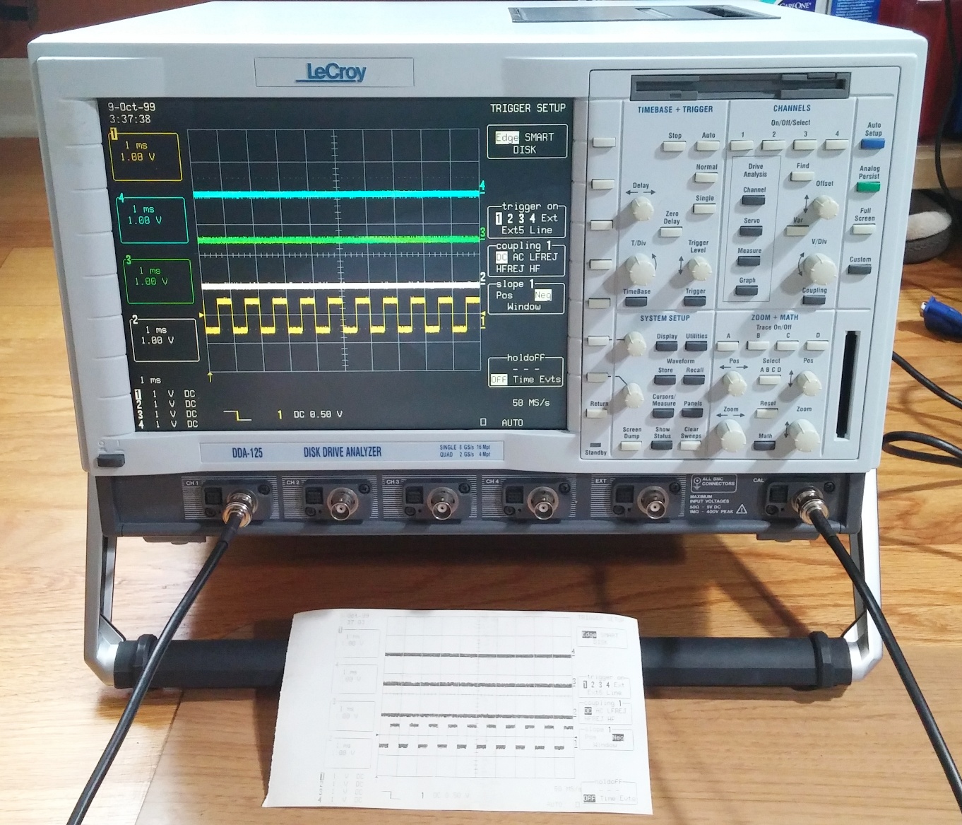
Picked up a DDA-125 sold as not powering up, and while the first few power cycles didn't yield anything, it suddenly came to life after that, and I ran it long enough to verify the printer, some basic acquisition system stuff, the cal signal, all four inputs, etc... seemed to be working great.  Hasn't powered up successfully since then.


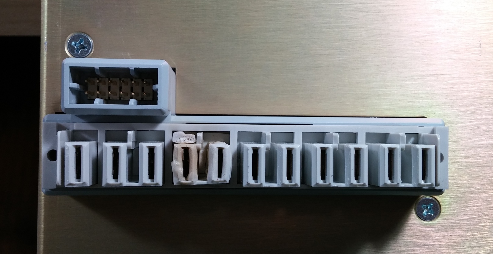
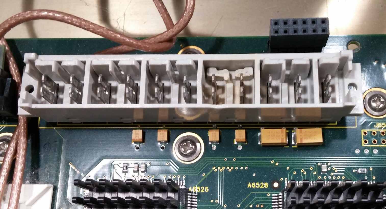
So, suspecting the power supply immediately, I set around to take things apart.  Got all the screws out of the power supply and had a lot of trouble getting it to come off - enough that it seemed like there was another screw somewhere.... but eventually the connector gave out and I saw what caused it - almost identical melting of the big power connector.


The PSU's filtering is impressive: AC input goes into an inline RFI filter, then this shielded filter module in the power supply (bottom, with the yellow tape), then into the switcher, then through a massive choke for each rail with bulk caps as well as smaller decoupling caps right on the contacts (in two sizes, no less).


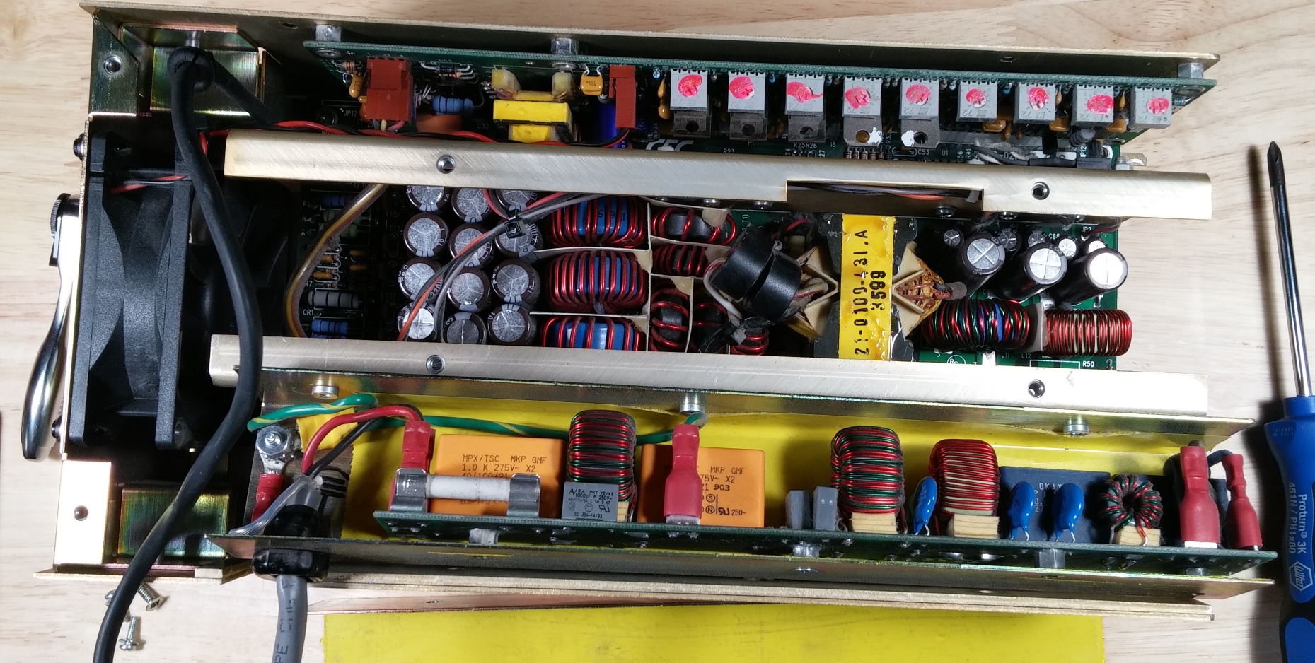
What's more, I opened up the power supply and in addition to taking some measurements of the output voltage, I took some pics with the thermal camera.  Most of the bits heating up quickly were power resistors, but the one part that heated up but wasn't a resistor.... was C93, the same snubber cap that failed in the OP's unit.  Not only that, the only discoloration of the PCB is right under that part too - I had been suspecting it in my preliminary analysis before I found this thread.  This thing may have come from a bad batch.... makes me want to look around the PSU board and just replace all of them or something.


Anyways, I have yet to pull the cap and verify that it was the main issue, but given the intermittent nature of my failure (my latest measurement of the rails actually yields pretty acceptable results, though I've measured way low previously), I wouldn't be surprised that it's gradually coming apart and replacing it will right things.

Otherwise, I plan on swapping the PSU fan with a new one of the current model (the one in their definitely is not living up to it's 29dB noise claim), and swapping the main ducted fan with something with just a hair higher CFM with lower noise.  Then I've got 2x64MB SIMMs on the way to double the system memory on the CPU card, the spec sheet says it can handle up to 128MB modules and the upgrade cost $15.


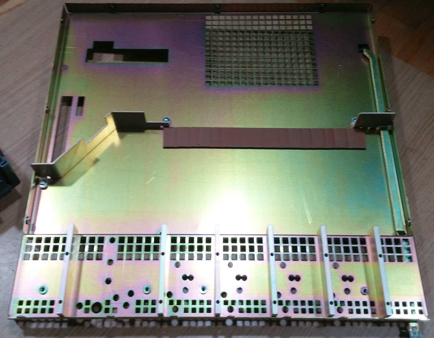
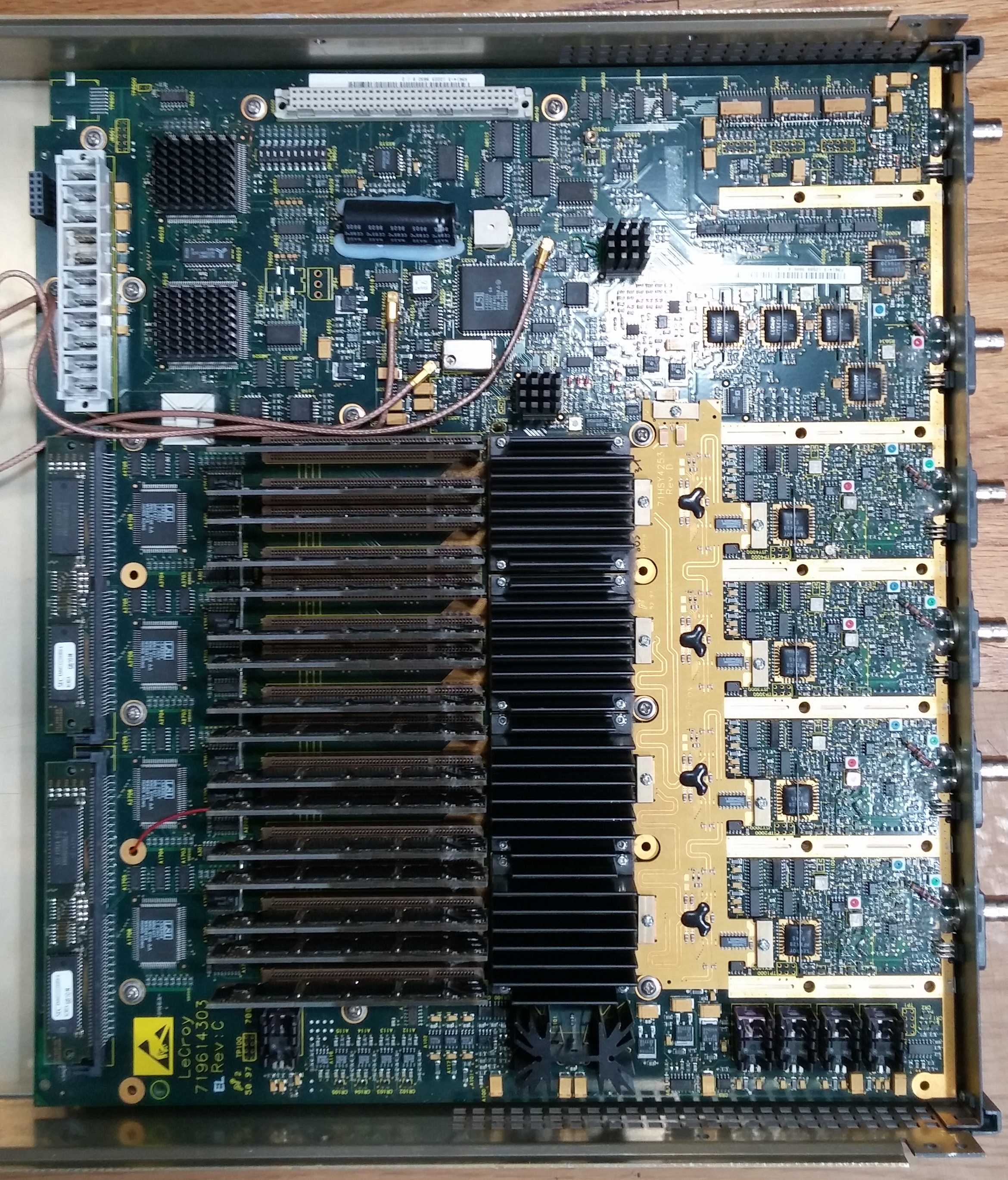
Took the top shield plate off to get a good look at the acquisition board too - mostly out of curiosity, but to check for damage related to the burned connector too.  31 screws (including the 6 top screws in the plastic BNC mounts) later, it's a nice looking board with a lot of custom parts.  Some high quality bodges to be found, and it looks like the input of the ADCs can be all routed to channel 2 (maybe 3?), verifying why I could get 8GS/s on a single channel when I was testing even though the manual claims you need a PP096 external connector to use all 4 ADCs at once.


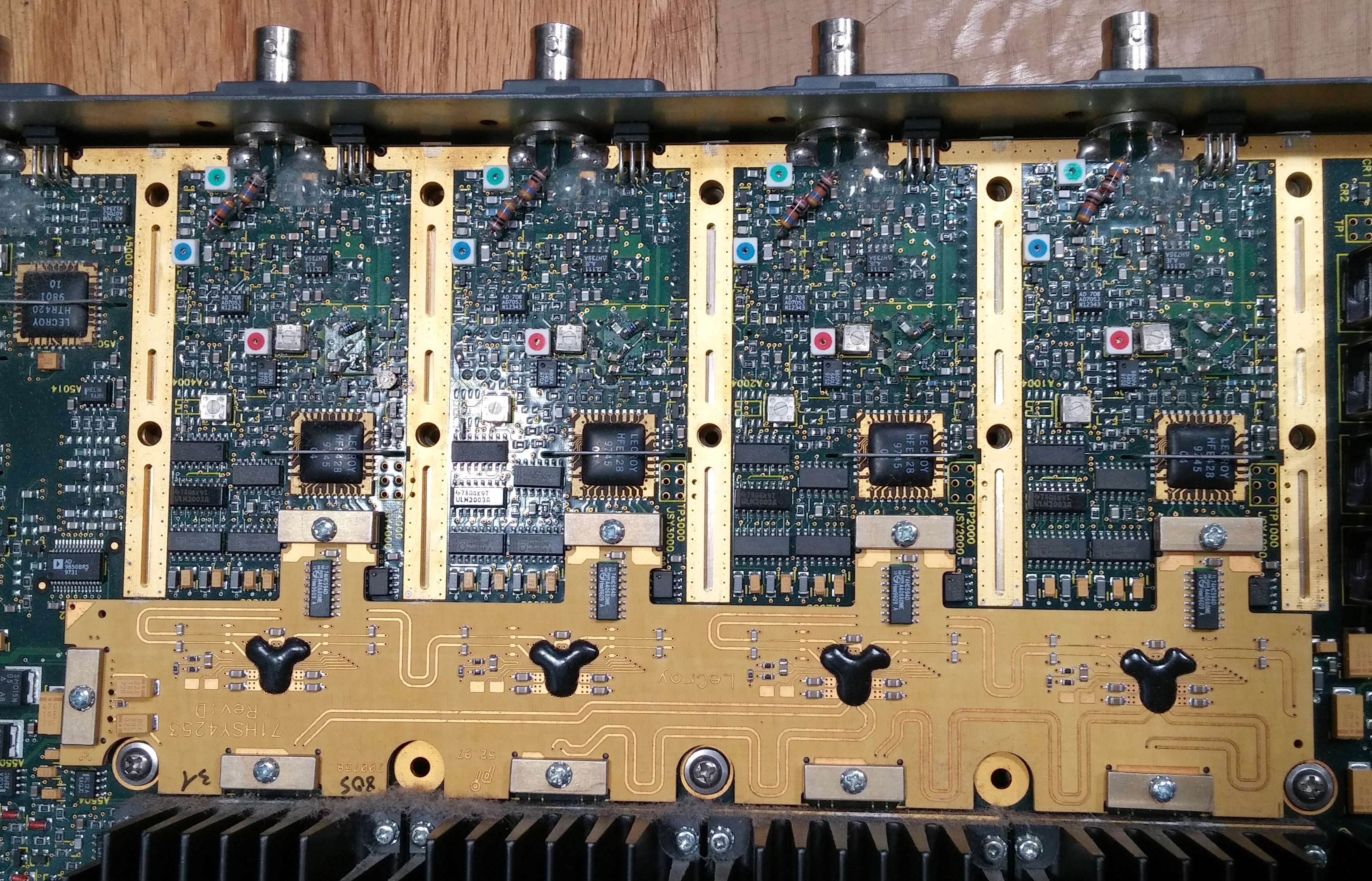
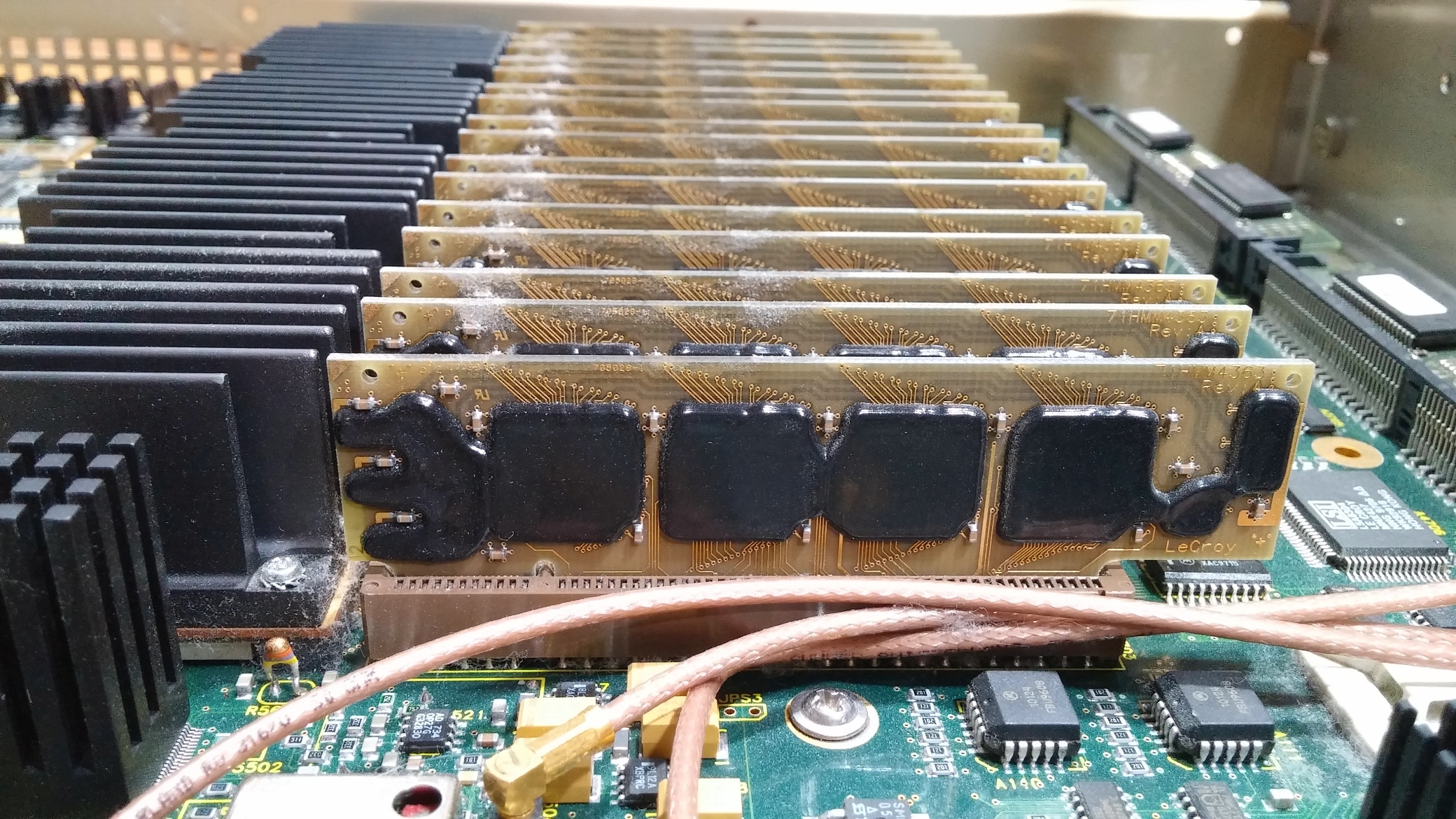
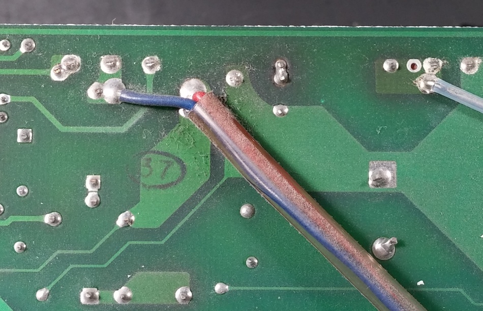
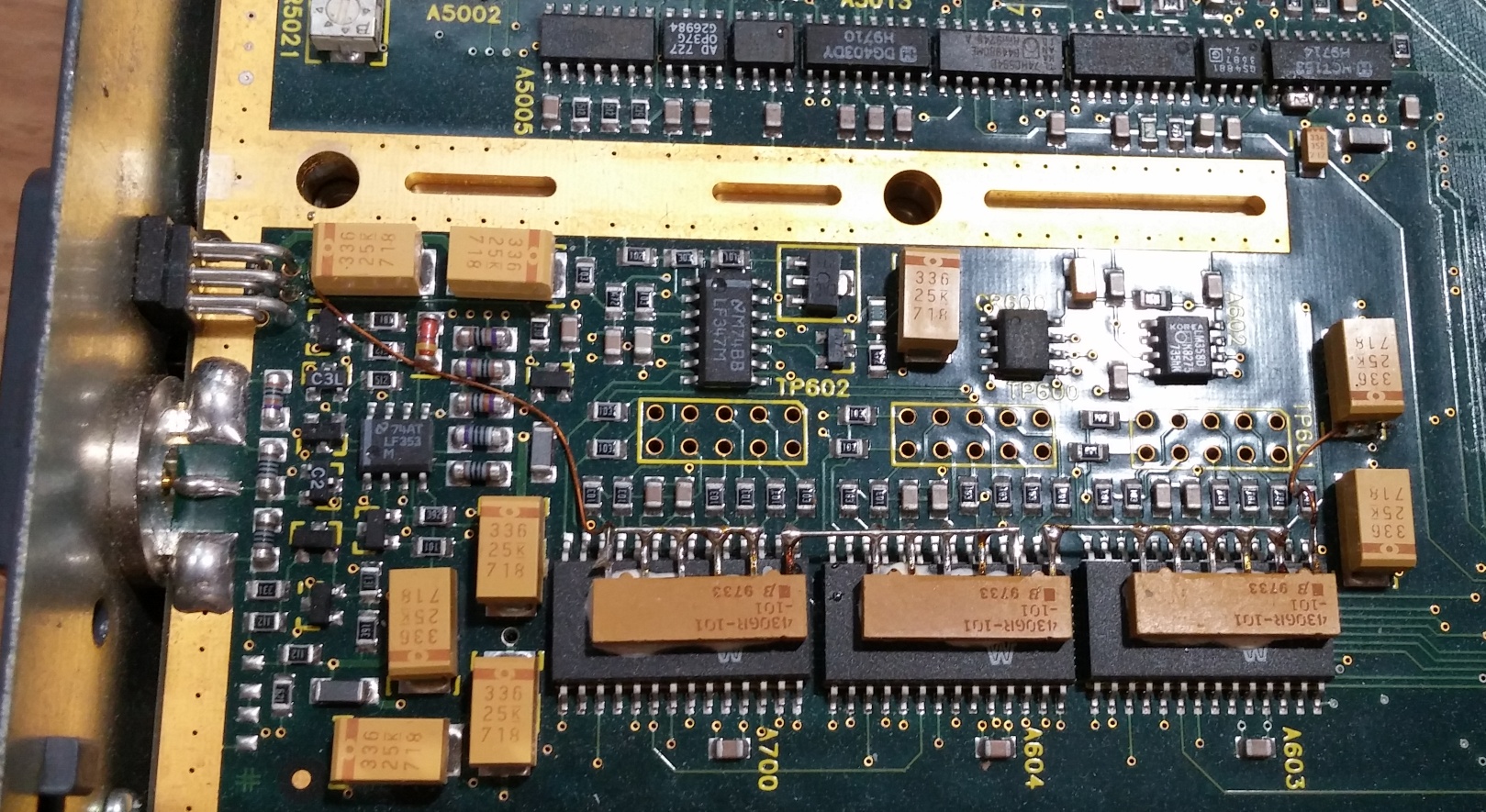
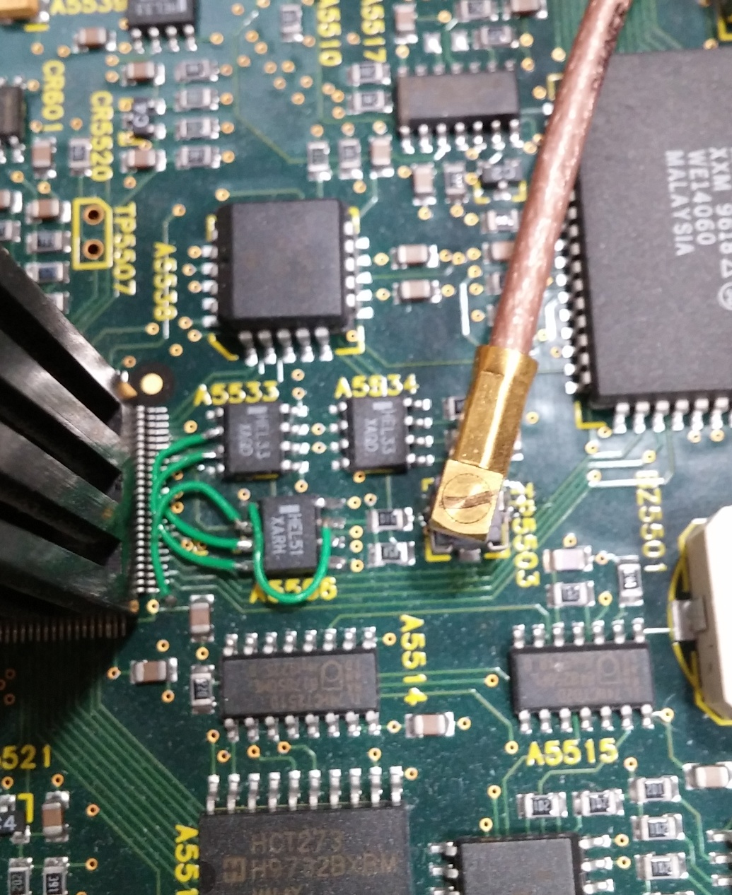
Then some fancy bodges on the acquisition board - it's just not a finished product until you have to glue a resistor array to a chip.


Also been really impressed with the metalwork.  You open the top and everything has a nice color and looks clean, then you get inside and it's really well designed, you can see shielding for the front end components as well as some ducting under the shield to make sure the ducted fan in back pulls all the air over the ADCs.


« Last Edit: August 30, 2017, 04:31:51 am by DaJMasta »
 

Offline Leo Bodnar

  • Frequent Contributor
  • **
  • Posts: 803
  • Country: gb
Re: LeCroy DDA-125 Stuck in standby (I think)
« Reply #42 on: August 30, 2017, 07:12:10 am »
Picked up a DDA-125 sold as not powering up...

...and it looks like the input of the ADCs can be all routed to channel 2 (maybe 3?), verifying why I could get 8GS/s on a single channel when I was testing even though the manual claims you need a PP096 external connector to use all 4 ADCs at once.
Very odd, this acquisition board looks like DDA-120 / LC574 series.  Both front end and add-on channel multiplexer/combiner.
Can you verify its frontend bandwidth or risetime?

Did you get it from motion_constrained?

Leo

One of my DDA-125 frontends (I have replaced a few relays):
« Last Edit: August 30, 2017, 07:34:25 am by Leo Bodnar »
 

Online DaJMasta

  • Super Contributor
  • ***
  • Posts: 2296
  • Country: us
    • medpants.com
Re: LeCroy DDA-125 Stuck in standby (I think)
« Reply #43 on: August 30, 2017, 07:35:51 am »
Yep, one of the two they recently sold.  From the board number on that front end amp to ADC routing board of sorts, my part number is one lower but two revisions later.

I didn't run particular tests to verify that it was actually sampling at 8GS/s, but on channel two in single channel mode, it was reporting 8GS/s, and since there's an eeprom in those little bridging adapters, I figured it would know if only one channel was actually getting the signal.
 

Offline Leo Bodnar

  • Frequent Contributor
  • **
  • Posts: 803
  • Country: gb
Re: LeCroy DDA-125 Stuck in standby (I think)
« Reply #44 on: August 30, 2017, 07:47:23 am »
I have checked the other one they have sold (I got it) and it has the standard acq board (like the one I have posted.)
You got yourself an interesting instrument.
I know of someone who thinks that DDA-120 with LCD would have been the best instrument from LC series and it looks like it exists and you have it.
Try checking if it's really 1.5GHz BW or 1.0GHz like it would be on DDA-120.  This would be the only downside and possibly caused by complicated channel multiplexer/combiner - that add on mezzanine board.  On DDA-125 it is much simpler and does not have any active parts.
Leo

« Last Edit: August 30, 2017, 08:02:05 am by Leo Bodnar »
 

Online DaJMasta

  • Super Contributor
  • ***
  • Posts: 2296
  • Country: us
    • medpants.com
Re: LeCroy DDA-125 Stuck in standby (I think)
« Reply #45 on: August 30, 2017, 08:00:32 am »
Interesting!  It's SN 30005, manufactured on the 7th of September, 1999, if that helps anyone get an idea of when such a change may have been made.  I wonder if there are LC684s that are the same way.
 

Online DaJMasta

  • Super Contributor
  • ***
  • Posts: 2296
  • Country: us
    • medpants.com
Re: LeCroy DDA-125 Stuck in standby (I think)
« Reply #46 on: September 01, 2017, 05:22:56 am »
A little update on my repair:

I ended up pulling C93, but while it was discolored and the PCB was singed, it measured alright.  Replaced with a 500pF 1kV cap I had in a box, which read a little under so it should technically still be at the edge of the 20% tolerance of the original part.  I haven't tried powering up the full thing, but most of that is because of a strange happening.

In measuring the outputs again, everything seems to be in spec except for the -15V rail.  As it turns out, the spec is VERY broad, so even 5.8V on a 6V rail is actually still 200mV above minimum spec, and that -2.5V "-2V" rail is still within the -2.6V maximum (minimum?) spec.  However, the -15V rail was reading high, often under -16V.  So I went to adjust the trimpot and found that not only did it make almost no difference, but the potential was gradually rising... it got to under -17V by the time I powered it down after trying to adjust it.

I also found that those bigger resistors on the output are probably actually supposed to run hot... looks like at the -15V spec, R2, which is in parallel with the -15V rail, dissipates about a watt.  I guess to keep noise down they've got a constant resistive load right on the output.  Now there's a chance when the rail is more heavily loaded it will be pulled down to where it should be, but with the constant load and no response on the adjustment trimpot, I think the rail regulation just isn't working.

Checked BR3, the rectifier for the rail, it was fine.  Checked Q7 and at least on the diode check it matched the other transistors next to it on functional rails... so I don't think it's that.  But there's only so many active parts just on this rail... so maybe the current loading measurement amp on the main board, U1, does not have a high impedance input, or maybe the LM358, U3 on the housekeeping board, is a dead amp and just isn't driving the adjustment transistor at all?

It's hard to say, maybe have to probe around with a scope or something.  If I can't verify a failure, I may just try to power the thing up and see, but it's unsettling seeing a rail with active regulation gradually drifting up - maybe the regulation is stuck and it's increasing resistance of the load resistor as it heats?


Also, it's real annoying working on the power supply out of its chassis because of the one heatsink plate that's covered in thermal paste.  Got some on my fingers many times already, but not so many times that I want to wipe it off and reapply.... at least not yet.
« Last Edit: September 01, 2017, 06:03:10 am by DaJMasta »
 

Online DaJMasta

  • Super Contributor
  • ***
  • Posts: 2296
  • Country: us
    • medpants.com
Re: LeCroy DDA-125 Stuck in standby (I think)
« Reply #47 on: September 03, 2017, 05:03:33 am »
Probed around, removed a couple more parts... but couldn't find another failure.  Applied a 50 ohm load to the -15V rail and suddenly it was being regulated again, so I mostly assembled it (leaving the power supply top off for thermal camera work), and turned it on - and it powered up.  Got my thermal pictures and the resistors were still getting real hot, but it didn't report any errors or anything.  Powered off, powered on, doesn't come up - the main fan also turns on briefly and drops, so I figure it's time to check the fan power supply.

The -12V rail was reading something like -13.2V, so I adjusted it down and hooked up the fan to verify it could run loaded - it did.

So there are a couple of directions to go, I think I need to adjust the -15V line again - while it held regulation, I think it was to -15.6, which is technically out of spec, so I figure it's worth tweaking down.  It could also be worth desoldering the thermal switch and trying to see if it's not opening properly - I think I measured a 2k resistance across when powered down, in circuit.

Otherwise, I want to monitor the shutdown signals going to the power supply from the other board connector.  If those above aren't doing it, there's a chance there's some sort of malfunction on the acquisition board's monitoring circuits that wasn't visible damage.

As for the cooked connector, I used an xacto knife to make sure the opening was as wide as the others and tried to shape up the sides of the melted bits a little, I also sprayed them all with contact cleaner (PSU side).  It feels like each pair of contacts on the PSU side is a separate bit of plastic held in by the big housing, and the metal contacts themselves are soldered directly to the board, so if it turns out that the connector is near impossible to find, finding the little contact pairs may still be possible.  Don't think I'll swap mine because it does seem to power up at least sometimes fine, but who knows.  Not yet sure what's causing my intermittent failure.

Attached the image from the thermal camera of the back half or so of the PSU, installed in the successfully powered up unit, and you can see the temps we're seeing after only 45 seconds or so.  Thermals should be better when the supply is ducted properly with its top installed, but they're still running hotter than I'd like.  The bright one on the right is R12 on the housekeeping board and for the life of me I can't figure out why it's running so hot.  The ones in the center are fixed loads on the rails and are right in front of the fan, so i figure they are intentional, but R12 maybe isn't.  I also think that C93 itself probably isn't prone to failure.... it's just next to two resistors that heat up and gradually cook it.  A 2W on one side, a 5W on the other, and both get up there somewhat.
« Last Edit: September 03, 2017, 05:07:03 am by DaJMasta »
 

Offline IanMacdonald

  • Frequent Contributor
  • **
  • Posts: 943
  • Country: gb
    • IWR Consultancy
Re: LeCroy DDA-125 Stuck in standby (I think)
« Reply #48 on: September 03, 2017, 07:25:53 am »
Not sure if you solved the resistor value issue, but it's likely a 47R with a missing purple band.
 

Online DaJMasta

  • Super Contributor
  • ***
  • Posts: 2296
  • Country: us
    • medpants.com
Re: LeCroy DDA-125 Stuck in standby (I think)
« Reply #49 on: September 07, 2017, 03:22:10 am »
So I think I've found it.

Checked the thermal switch, monitored the shutdown lines, tweaked the -15V rail, monitored voltages from the processor card when trying to power up... nothing.  But, sometimes I could get a hint of a partial startup still, so I started wiggling the power supply.  Pushing to the sides or front/back didn't do it.... but pressing down on the fan in the back got it to instantly boot.  The problem is the connector, and I think it's the same problem that caused the melting initially.


My theory, is that the contacts just don't make good contact... or the board that's giving them rigidity (though properly supported with screws to the chassis all around the connectors) has flexed with age.  This means that the melted contact probably wasn't a surge condition... it was just a sort of weak pressure point with too high contact resistance trying to pass several amps.  The trick is, I'm not sure how to get the connector housing off to clean/fix this on the PSU side, so I think my potential options would be to jam shims in (seems like a bad idea, honestly), or to try and tin the contacts on the acquisition board to make a little more height and thickness (though, probably less even contact and then there's durability issues).  So I don't really know what the best route forward is.

I will try to get the connector housing off and take a look at the bits on the PSU side, but we'll see how far that gets me.

In other news, it's this scope's 18th birthday tomorrow.


Share me

Digg  Facebook  SlashDot  Delicious  Technorati  Twitter  Google  Yahoo
Smf