i will check resistor again...i really want this time to get this beast of a scope working !!! i need a challenge !!! in my photo of the pcb it shows two tant capacitors and i forgot to solder them back in circuit before storing the scope...so not sure of the values or voltage of the caps  any idea anyone
With study of the App Note
vk6zgo linked and the Datasheet I linked in reply #16 AND your pics, the caps should be 100uF (C112) and 10uF (C118?) (but I'd use 22uF) and all at least 50V rated and only ELECTROLYTIC.
BTW, meter out both these caps footprints and check against the overlay which is the GND pin. (to be sure, to be sure

)
You've still got more to work though IMO, pics are barely enough detail, there's parts of the circuit we can't see, the switching Mosfet/BJT for one and trying to identify the flyback VDD diode.
Please confirm if the via next to pin 8 is GND. (3842)
Where does pin 5 go?
What component is the TO-92?
As SAUL BRITTO says replace the opto too.
Another pic from a bit further out and lit in the currently dark areas would be a great help.
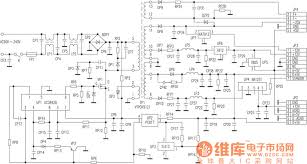
Try as I might to find a "nice" circuit example similar to what we can see in the OP's images WITH opto feedback, a flyback PSU winding, multi PSU caps and multi outputs, this is the closest I could: